1
Barke Module
User Manual
Version
0.0.1
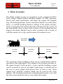
Opening the switch will activate the breaking section, while
closing it will disable it. Using the Brake Module with a
signal, connect the normally open (NO) contact of a relay
synchronized with the green light of the signal. As the signal will
turn to green, the relay will be activated, and closing its contacts will
disable the breaking.
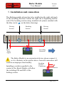
Installing the Brake Module on the layout is done with the supplied
screws and spacers. For positioning and mounting see figure below:
The diodes inside the Brake Modul supports a nominal current of 1A
in continuous mode but can withstand to peaks of 30A for a period of
8 miliseconds. In case of short circuit on the line, the protection of
digital command stations or boosters cuts the output voltage faster
than 8 milliseconds, thus performing as a circuit protection for the
Brake Modules.
6. Recommandation
The tOm Brake Modules should be installed as close as
the track sections; the electrical connections should be
multi-conductor wire with appropriate section. Cut the
strictly to the required length. We recommend using
diameter copper wire.
possible to
made with
conductors
0.25 mm2
Page 6 of 8