1
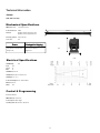
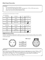
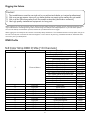
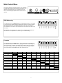
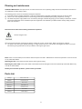
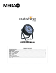
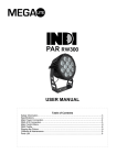
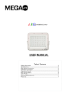
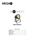
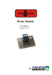
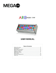
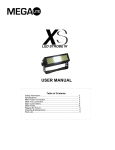
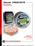
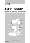
USER MANUAL
Table of Contents
Safety Information……………………………………………………………………………………………. 3
Technical Information.…………………………………………………………………………………….. 4
Main Power Connection…………………………………………………………………………………..5
DMX-512 Connection…………………………………………………………………...……………...... 5
Rigging the Fixture............................................................................................................6
DMX Profile......................................................................................................................... 6
Main Control………………….................................................................................................. 7
Cleaning & Maintenance.............................................................................................. 8
Check that the unit has not been damaged during transport
Protection Against Fire
1.
3.
4.
5.
6.
Maintain a minimum of 1 foot distance from any type of flame.
Replace fuse only with the specified type and rating.
Do Not install the unit to close to a heat source.
Make sure cable are properly secured away from unit movement.
Maximum surface operating temperature 80º.
Protection Against Fire
1.
2.
3.
4.
Disconnect power before servicing.
For connection to main power supply proceed to page 5.
This unit must be earthed. (electronically grounded)
Do not expose unit to rain or moisture.
Protection Against Mechanical Hazards
1. Use safety chain when hanging unit.
2. Use quality clamps or bolts when positioning unit
3. Do not open unit while it is on, risk of electrical shock.
3
Technical Information
Fixture
405– N-E Color Strip
Mechanical Specifications
DMX Connectors:
3-pin XLR connectors
Power Connection:
In/Out
Thermal:
Maximum ambient temperature 40° C
Maximum surface temperature 60° C
Fastening System:
Dual end mount
42.12 ”
)OLFNHU)UHH<HV
Fixture
Packaged for Shipping
Size: 42.12”L x 2.75”W x 4.5”H
Size: 42.5”L x 5”W x 5.”H
Weight: 5 lbs
Weight: 6 lbs
4.5
2.75
Electrical Specifications
LED Quantity:
Red:
Green:
Blue:
252
108
72
72
LED Diameter: 10 mm
LED Lifetime: 60,000 to 100,000 hours
LED Angle: 35° ( ± 5º )
Power Consumption: 100 - 240V 50/60 Hz
Ballast: Electronic
Watts:
18.8
Control & Programming
Protocol: DMX 512
DMX Channels: 13 Channels
Control options: Audio-trigger
Operating mode: Master/Slave, Stand alone
4
Main Power Connection
Caution!
1.
2.
3.
4.
Do not connect fixture to a dimmer system.
This unit has Auto switching power supply. It will respond to 110V or 220V automatically
This unit must be earthed. (electronically grounded)
Replace fuse only with the specified type and rating.
The occupation of the connection-cable is as follows:
110V Connection
Cable (USA)
Cable (EU)
Pin
Connection
Black
Brown
Live
L
White
Light Blue
Neutral
N
Green
Yellow/Green
Ground
Cable (USA)
Cable (EU)
Pin
Connection
Black
Brown
Live
L
White
Light Blue
Live
N
Green
Yellow/Green
Neutral
220V Connection
DMX-512 Connection
The fixture is equipped with 3 pin XLR Sockets for DMX input and output. The sockets are wired in parallel. Only use a shielded
twisted pair cable designed for RS-485 and 3 pin XLR plugs and connectors in order to connect the controller with the fixture or
the fixture with another.
DMX—output
DMX—input
2
1
1. Shield
1
2
2. Signal (-)
3
3. Signal (+)
3
Caution!
At the last fixture the DMX signal needs to be terminated with a terminator. Solder a 120
Ohm resistor between the (-) and the (+) signal into a 3 pin XLR plug and plug it in to the
last fixture on the signal run. Pre-manufactured terminator plugs are available for
purchase from your Mega-Lite dealer (HOS-DMXT).
5
Rigging the fixture
Caution!
1.
2.
3.
4.
The installations must be carried out by an authorized dealer or trained professional.
Unit may cause severe injures if you have doubts concerning the safety do not install.
Unit is to be 24inches away from flammable materials (decoration material)
Use high quality installation equipment to hang unit.
When rigging a unit it is very important that you follow common safety procedures. Rigging requires extensive experience including but not limited to calculating working loads, material being used and periodic safety inspections. If you lack these qualifications, do not attempt the installation yourself, instead use a professional structural rigger.
When rigging the unit always be secured with a secondary safety attachment. The installation location of the projector has got to
be built in the way that it can hold 10 times the weight for 1 hour with out any harming. Installation should be checked at least
one time a year by a skilled person.
DMX Profile
N-E Color Strip DMX Profile (13 Channels)
DMX Channel
Function
1
Dimmer, Macro
2
3
4
5
6
7
8
9
10
11
12
13
LED Color
LED Color
LED Color
LED Color
LED Color
LED Color
LED Color
LED Color
LED Color
LED Color
LED Color
LED Color
Description
Dimmer (Ch 2-13 dimmer valid)
Strobe (Ch 1-13 Dimmer valid)
Color Fade slow to fast
Color Snaps slow to fast
Color Chase (red, purple) slow to fast
Color Chase (red, yellow) slow to fast
Color Chase (green, aqua) slow to fast
Color Chase (blue, purple) slow to fast
Color Chase (blue, aqua) slow to fast
Color Chase (purple, green) slow to fast
Color Chase (yellow, blue) slow to fast
Color Chase (aqua, red) slow to fast
Color Chase 1 slow to fast
Color Chase 2 slow to fast
Color Chase 3 slow to fast
Red full bar
Green full bar
Blue full bar
Red 1st segment
Green 1st segment
Blue 1st segment
Red 2nd segment
Green 2nd segment
Blue 2nd segment
Red 3rd segment
Green 3rd segment
Blue 3rd segment
6
Value
0-10
11-51
84-115
116-123
124-139
140-147
148-155
156-163
164-179
180-195
196-211
212-227
228-243
244-251
252-255
0-255
0-255
0-255
0-255
0-255
0-255
0-255
0-255
0-255
0-255
0-255
0-255
Main Control Menu
FUSE 2A 100V– 240V
9 10
256
8
128
6 7
064
5
016
008
MIC
4
032
MAX
3
004
MIN
2
002
1
001
The control board on the fixture base is your interface
to access and control all the functions on the unit. Its
dipswitch interface gives you a code view of the options. The following will explain each function and its
options.
DMX 512 SIGNAL
DMX Addressing
8
9 10
008
016
032
3
4
5
6
008
016
032
064
9 10
ON
004
8
2
004
7
002
1
256
7
256
6
128
5
128
4
064
3
002
2
001
1
001
Turn dipswitch 10 to the Down position. Each dipswitch from 1 to 9 holds
a numerical value located below the dipswitch. Add the numerical value to
get the desired fixture start address channel. The user must assign a
start address on the fixture that indicates the first channel reserved in the
controller.
ON
DMX
For example, if you wish the first unit to start on address channel 85 you
will need to turn on dipswitch 1,3,5 and 7 (1+4+16+64=85)
Turn dipswitch 10 to the UP position. This function will turn on the functions that will allow the unit to run a preprogram function. Additionally, this
unit may serve as a master unit where other units will copy it’s functions.
To create a master unit connect the XLR cable from the output to the input on the next unit. And address the next unit as fixture 1.
FUNCTION
1
RED
ON
GREEN
2
4
5
6
FASTES
ON
CYAN
7
8
9
10
ON
BLUE
STROBE
3
FUN
Functions
ON
SLOW
MID
FAST
COLOR FADE
SLOW
MID
FAST
FASTES
COLOR SNAP
SLOW
MID
FAST
FASTES
CHASE LIGHT
SLOW
MID
FAST
FASTES
SOUND ACTIVATED RAINBOW
DMX
1
MAGENTA YELLOW
ON
ON
ON
ON
2
4
8
16
7
32
64
128
256
ON
ON
ON
DMX
Cleaning and maintenance
Installation Maintenance: The operator has to make sure that the unit is operating safely and has the installations and electronics checked by an expert every 2 years.
The following points have to be considered during the inspection:
1) All screws used for installing the device or part of the device have to be tightly connected and must not be corroded.
2) There must not be any deformations on the housing, fixation and installation spots (ceiling, suspension, trussing).
3) The electronic power supply cables must not show any damages, material fatigue (e.g. porous cables) or sediments. Further
instructions depending on the installation spot and usage have to be adhered by a skilled installer and any safety problems
have to be removed.
Disconnect from mains before starting maintenance operation!
Caution Danger to life!
We recommend a frequent cleaning of the device. Please use a moist, lint free cloth. Never use alcohol or solvents!
1) The plastic cover will require periodic cleaning on usage and environment. Environment with foggers will require more periodic cleaning as fog fluid tends to build up residues, reducing the light output.
Note: There is no serviceable parts inside the device except for the LED’s. Maintenance and service operations are to be carried
out by authorized dealers.
Replacing the fuse: Only replace the fuse with the same type and rating.
Replacing the power cable: If the power cable of this device becomes damaged, it has to be replaced by authorized dealers only
In order to avoid hazards.
Should you have further questions , please contact your dealer.
Parts List
4050-gc
Plastic clear cover
4050-ec
Plastic end caps
4050-ledmod
LED module
4050-mainc
Main PCB card
4000-dmx
XLR Connections
4000-fh
Fuse Holder
4050-ps
Power Supply
8
Mega-Lite
5718 Kenwick St
San Antonio, TX 78238
Ph 210-684-2600 Fax 210-855-6279
www.mega-lite.com / [email protected]