1
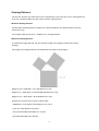
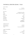
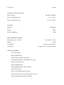
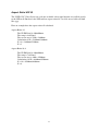
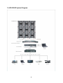
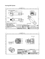
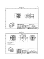
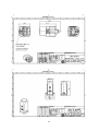
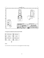
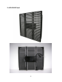
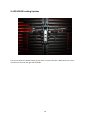
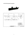
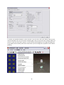
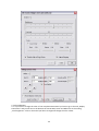
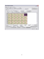
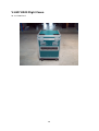
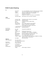
V:LED VIA20
Manual
Summary
1. Safety Notes S.2
2. Viewing Distance S.3
3. LED Binning S.4
4. Pixel Failure Rate S.4
5. Product Description S.5
6. Specification S.6
7. Aspect Ratio S.9
8. System Diagram S.10
9. Harting PushPull S.11
10. Rental S.15
11. Locking System S.16
12. Hanging Bar S.17
13. Software S.18
14. VSC LED Controller S.25
15. Flight Cases S.26
16. Trouble Shooting S.27
1
Thank you for purchasing this V:LED product. For your own safety, please read the
instruction manual carefully before turn on the product for the first time.
SAFETY NOTES
Each person which is responsible for the installation, the use or service of this unit must be:
- qualified
- has to follow the instructions in this manual.
WARNING! Be careful when using the device. You risk an electrical shock from high voltage, if you
touch the wires!
The device has left our company in manufacturer proofed state. To maintain this status and to
ensure a permanent safe operation, it is absolutely necessary to follow the safety instructions and
warnings in this manual.
IMPORTANT: Errors, caused by not following these instructions are not covered by the warranty. The
manufacturer will not accept liability for any resulting defects or problems.
Keep the unit away from radiators or other heat sources!
If the unit has been exposed to tremendous temperature changes (e.g. after transportation), do not
turn it on immediately. The resulting condensation could damage the unit. Don`t switch unit on until
the device reaches room temperature.
This device belongs to protection class I. Therefore, it is imperative that the green/yellow wire is
connected to the earth contact of the plug. The electrical connection must be made by a qualified
person.
Make sure that the cable has never been squeezed or damaged by sharp objects. Check the device
and the cables regularly.
If the cable is damaged, it must be replaced immediately by the manufacturer, its service agent or a
qualified person in order to avoid danger.
Ensure that wires never come in contact with other wires! Handle the power cord and all
connections with caution!
Make sure that the line voltage is not higher than the voltage specified in this manual.
Disconnect the unit from the AC mains when it is not in use or when cleaning it. Disconnect the
connection only by pulling the cable plug.
Defects caused by modifications of the device by unqualified handling or an unqualified person are
not covered by the warranty.
Keep the product away from children and unskilled people.
There are no wear parts in the device. Maintenance and service must be performed only by an
authorized service partner.
Note:
If a earth leakage circuit breaker will be used for a fixed installation, you have to check the leakage
current of the used power supplies. Inside the VIA20 Panel is one MeanWell power supply, whose
leakage current is <3,5mA. The VIA20 Panel has 1x power supply and the max. leakage current can be
3,5mA. If you use a 30mA earth leakage circuit breaker you can connect 8x VIA20 Panel with the
breaker.
The LED-Panel has an inrush current of 30 Ampere per Panel. A safety fuse must have the
specification „dull“.
Cooling:
If the sun is shinning a LED-Wall of black Panel will be heating-up pretty fast. In the case of sunshine
or high ambient temperature there must be a circulation of air behind the LED Wall. Otherwise the
power supplies shut down automatically at +65°.
LMP advise to use a cooling system for fixed installations of LED Walls.
The external Fans at the VIA20 Panel will start automatically at 50°.
2
Viewing Distance
Like the min. distance you must have if you are watching TV you must have a min. viewing distance
if you use a VLED LED-Wall, that the viewer will have a good picture.
Minimum Viewing Distance:
The Minimum Viewing Distance (in Meter) of a VLED LED-Wall is the space between the Pixels
measured in mm:
For example: 10mm Pixel Pitch = 10 Meter min. Viewing Distance.
Maximum Viewing Distance:
To calculate the right LED wall size you need the length of the diagonal of the Event hall for
example.
The length of the diagonal will be calculated with the sentence of Phytagora.
Diagonal / 10 = VLED-Wall – min. LED Wall size in sqm
Diagonal / 5 = VLED-Wall – recommended LED Wall size in sqm
Diagonal / 3,5 = VLED-Wall – ideal LED Wall size in sqm
Example for a Screen with an area of 120m x 60m
= 18000sqm => The length of the Diagonal is ca. 135 m.
> The min. VLED Wall size is 13,5qm
> The recommended VLED Wall size is 27 sqm.
> The ideal VLED Wall size is 38 sqm.
3
LED Binning
If the Production of LED’s will be at different points of time the LED’s have tolerances.
For Example:
Rot
Grün
Blau
620 nm +/- 2,5 nm
520 nm +/- 2,5 nm
470 nm +/- 2,5 nm
If a client likes to buy the same LED Panel like he bought before he will see a LED Binning tolerance.
The tolerance can be adjusted manually in the software.
Pixel Failure Rate
The Pixel Failure Rate or Blind Spot Rate is written in the VIA20 data sheet. The Pixel Failure Rate tells
you how many can be defective until the company LMP will do a warranty repair. If the client wish
the repair of the defective LED’s without the case of warranty he has to pay for these repairs.
4
Product Description
The V:LED VIA 20 LED panel is not only exceptionally robust (yet, despite this, compact and light), but
also absolutely reliable in its operation, and quick and easy to set up and configure. For the display of
the video content, unusually bright 3-colour SMD LEDs are used. Absolutely perfect colour-mixing is
ensured by outstanding binning. In addition, the VIA 20 offers outstanding contrast and sharpness of
image.
Due to its IP65 protection rating, it can also be recommended for outdoor use. Connection is by
means of quick couplers. Modular rigging gear is available for suspending the panels. Slings or
couplers can also be used to secure the panels quickly and safely to things like trusses.
Control is implemented through DVI grabbing. The software allows simple addressing and the setting
of parameters such as colour, contrast, etc. Available as an option, a scaler adjust the image from any
desired video source (such as FBAS, VGA etc.) to the corresponding size of the LED wall.
5
TECHNICAL SPECIFICATIONS - VIA20
OPTICAL SYSTEM
Fixed Optics
Optics
Beam Angle
120° horizontal/verticall
LED-SOURCE
LEDs
1024 SMD Multicolour LEDs
Colours
1024x red, 1024x green, 1024x blue
Diffusor
No
LED-Pixel Pitch
20 mm
Brightness
3.500 nits
Colour Mixing
RGB
LED-Lifetime
> 50.000 Hours
Blind Spot Rate
<1/10.000
LED-Wavelength
red 620-625 nm,
green 525-530 nm,
blue 466-471 nm
TEMPERATURE RANGE
Ambient Temperature
-20°/+50° C
Operating Temperature
Max. 60° C
Cooling
Fan Auto-Control from 50° C
CONTROL & PROGRAMMING
Protocol
DVI
Control Software
LED Studio
Data Cable
RJ45 Waterproofed
Data Refresh Rate
1.200 Hz
6
Grey Lavel
> 14 Bit
TECHNICAL SPECIFICATIONS
90-240 V 50-60 Hz
Mains Voltage
Power Consumption max.
1,3 A at 230 V
Power Consumption avg.
0,71 A at 230 V
HOUSING
Aluminium
Material
Colour
Black
IP Class (Housing)
IP65
MEASUREMENTS/WEIGHT
64,0 x 64,0 x 7,5 cm
Measurements (L x W x H)
Weight
9,0 kg
Assembling
Quick Lock Connectors
Certificates
CE, EMC class A EN55022, RoHs
SPECIAL FEATURES
35% Transparency
Robust Metal Frame
Panel Contains All Electronic Parts
No Additional Ethernet-Switch/PSU Necessary
Short-Circuit Protection
Hot Swap/Plug & Play
Harting PushPull Data- & Power Plugs
Quick Lock System
90° Curveable Horizontal & Vertical
Grapical User Interface / (No Adressing necessary)
Camera Suitable Refresh Rate 1.200 Hz
7
DVI Display Grabbing
Compatible To Standard Mediaserver
8
Aspect Ratio VSF10
The VLED VSC Video Scaler can scale the available video signal that the size will fit exactly
to the LED wall. But hasn’t the LED wall an aspect ratio of 4:3 or 16:9 soccer balls will look
like eggs.
Here an example how the aspect ratio will calculated.
Aspect Ratio 4:3
The VLED Panel is 640x640mm
The setup is 8x6 Panel
The screen area is 5120 x 3840mm
Calculation: 4/X = 5120mm/3840mm
X = 4 x 3840mm/5120mm
X=3
Aspect Ratio 16:9
The VLED Panel is 640x640mm
The setup is 7x4 Panel
The screen area is 4480 x 2560mm
Calculation: 16/X = 4480mm/2560mm
X = 16 x 2560mm/4480mm
X=9
9
V:LED VIA20 System Diagram
10
Harting HAN System
11
12
13
Harting Push Pull RJ45 CAT PIN-Out Standard 568B
Note!
The connectors in the manual can’t be hot plugged under 230VAC voltage.
14
V:LED VIA20 Panel
15
V:LED VIA20 Locking System
The picture shows the VIA20 Locking System with a 4 point connector. Additionally are 2 point
connector for the left and right side available.
16
V:LED VIA20 Adjustable Hanging Bar
17
Manual Software LED Studio
(Note! All values in the screen shots are only as an example. Don’t use these for your system)
1. Software Settings
1.1 Install the software LED Studio with a double click on the file Setup.exe.
1.2. Different Software Packages will be shown. Choose „Installing LED play software“.
1.3. You will be asked about a Serial Number. Use: 888888
1.4. Now the Start Window will appear.
1.5. In the Menu click on „Option“ and then on the menu subpoint „Software Setup“.
18
1.6. The „Software Setup“ window will appear and you have to type “linsn“. There isn’t an entry
window fort he password. Type it only.
1.7. Now the Password window will be shown. The Password is: 168
19
1.8. You will see three tabs. The “Receiver” tab must be used only if you receive a new and blank
Receiving Card. Then you can push the Button “Load from files” and choose the RCG file which LMP
provides you.
1.9. Finally you have to push the Button „Send to receiver“ and „Save to receiver“.
1.10. To do the addressing of the VIA20 Panels you have to go to the tab „Display connection”.
20
1.11. The first thing you have to do is to write your Panel quantity horizontal and vertical into the
windows „Horizontal card“ and „Vertical card“ the software will build automatically your wall in the
window in the middle.
Click on the first Panel in your map which has a direct connection to the LED Controller and put in the
value 32 for the width and Height at the bottom of the software. The software gives automatically
the first Panel you clicked the Order No. 1. Now you have to click on every Panel like you wired your
VIA20 Panels. In the end you have to push the “Send to receiver“ and „Save to receiver“ Button.
1.12. The settings of the tab „Sender“ should look like the next picture.
21
1.13. After you pushed the Button „Save to Sender“ you can click on the „Exit“ Button. Now you can
close the windows until you use the start window again. Here you have two more settings which you
can use. Under the menu point „Option“ you will find the point Brightness to change the brightness
of the VIA20 screen and the point Screen Area where you can change the X/Y position for the Video
grabbing.
22
2. Color Calibration
2.1. If you have to change the color of one complete VIA20 Panel you have to go to the tab „Display
Connection“ and you will see at the bottom the entries Red, Green and Blue next to the writing
„Card brightness“. Click on the Panel you like to change and change the color values.
23
24
V:LED VSC LED Controller
The V:LED VSC LED controller offers a wide variety of video inputs to allow the connection of
cameras, media servers, DVD players or other video sources. If you wish to use the LED controller as
more than as a drive unit for a LED wall, it can also serve for the conversion of a video signal, in which
case the maximum latency or processing time is 1 frame.
The output section of the controller offers three video outputs. The VGA output can be used to drive
a preview monitor for the control of the input signal, whilst the DVI output signal is converted into a
digital signal format and routed via a DVI bridge to controller‘s integrated Sending Card. The Sending
Card integrated offers two CAT5 outputs that serve for the connection of the VSO/VSP/VIA LED wall.
The cable run to the first LED wall module in this case can be up to 100 metres in length. If cable runs
in excess of 100 metres are required, a CAT-LWL converter can be used; this is capable of spanning a
distance of 1 km.
The controller can be driven via an RJ11/USB interface or else integrated into an existing network via
its TCP/IP interface and remote-controlled through the network. By this means the controller is able
to scale pixels with precision, so that every input signal can be adjusted to the size of the LED wall
connected. The Sending Card integrated establishes the connection to the VSO/VSP/VIA LED wall by
means of a USB interface and the software LED Studio. This software is in worldwide use and offers
additional functions e.g. time-related brightness control.
If you want to scale an incoming Video signal for the size of the LED wall, you can set the scaling with
the Display Menu of the VSC LED Controller or per software.
For Example: You did the addressing and settings for your LED Wall with the Software LED Studio and
you connect a DVD-Player or a Camera to the VSC LED Controller.
At the front side of the Controller you will find the Button „Scale“. Please push that Button two times
until you see the writing Scale in the Display Menu of the Controller. If push the Buttons „UP“ or
„Down“ the display will show five menu points: „H-Size“, V-Size“, „H-Pos“, „V-Pos“ and „Step“ .
If you have a 10mm VSF Outdoor LED Wall, which has a size of 3,84x2,88m means that you have a
resolution of 384x288 Pixel.
Choose now the Menu point „H-Size“ and confirm the Entry with the „OK“ Button. A little star will
appear next to the Entry „H-Size“. Now you can change the value with the Buttons „UP“ and „Down“,
until you have the value 384. Confirm the Entry with the „OK“ Button. The star will disappear.
That you can change the values faster you can go to the menu point „Step“.
Here you can set the value to 1, 10 or 100. In that effect you can jump in bigger steps with „UP“ or
„Down“.
You have to do the same Steps for the menu point „V-Size“, until you reach the value 288 and
confirm it with the „OK“ Button.
Finally you can change the Offset with „H-Pos“ and „V-Pos“ that the scaled picture starts at another
position.
To save the scaling you have to press the „Save“ Button at the Controller then the „Save 1” or “Save
2” and at last the “OK” Button.
Advice: At the backside of the Controller you will find a VGA and DVI output. If you connect there a
Preview Monitor you can check the scaling.
Further Informations about the VSC LED Controller you will find in the VSP618 Manual.
25
V:LED VIA20 Flight Cases
for 5x VIA20 Panel
26
VIA20 Trouble Shooting
PC
Not cloned
Adapter
COM Port
Resolution
Use a Preview Monitor, connect to VGA output of the controller
VGA to DVI Adapter didn’t work. Only digital signals
Difficulties with MAC Book, virtual Windows
USB Driver not installed
Wrong VGA resolution, check data sheet of Controller
USB Connection
No Function, Check at "unactive controller"
Schedule Table
Receiving Card
Power
Data Line
LED Controller
Sending Card
Timing Entry which switch the screen to black
Wrong RCG-Datei
Timing Entry which shut down Power
defective
Check Video signal with Preview Monitor
Hang up, Check LED’s at CAT outputs
Power Supply for Sending Card defective
Internal data cable loose
USB Input defective
LINSN
Screen black
1. Receiving Card
Sending Card
Screen Pixel
Failure/Stripes
Controller
DVI cable
Output
Sending Card
Save
Didn’t Boot up
Display dead
Old Scaling
Analog vs. Digital
DVI Bridge
LED Wall
LED module black
Panel black
LED defective
Red Stripe
Stripes
Circuit Breaker
Change DVI or HDMI cable
Wrong output programmed
Save Button -> Save 1 Button -> OK Button
Backside Controller: DIP switches down not up
Check of internal data cable to display
Press Output Button to take it out
If you change the incoming signal from a digital to an analog
Signal you will have a black frame
Check connection
Loose data cable
In or Output of module defect
Loose CAT cable
Change LED strip
Heat Problem
Send again RCG file
Defective Power
Supply
Power Supply is defective
27