1
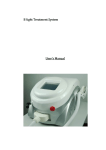
th 4 CONTROL SYSTEM USER MANUAL Copyright Statement Owner's Manual 4th CONTROL SYSTEM Copyright Statement GD Han’s Yueming Laser Technology co.,Ltd. All rights reserved. GD Han’s Yueming Laser Technology co.,Ltd (Han’s Yueming Laser hereafter) reserves the right to modify the products and product specifications described in this manual without advance notice. Han’s Yueming Laser is not responsible to any direct, indirect, or consequential damage or liability caused by improper use of this manual or the product. Han’s Yueming Laser owns the patent, copyright or any other intellectual property right of this product and the related software. No one shall duplicate, reproduce, process or use this product and its parts, unless authorized by Han’s Yueming Laser . All the name refered in this manual only for identification, if belongs to other company’s registered trademark or copyright, proprietary rights of the name belongs to their respective holder. -1- Foreword Thanks for purchasing the laser engraving machine control system of our company. Before operating, please read this manual carefully to ensure proper operation. Please keep the manual properly for reference. Since the configs are different, certain models do not have the functions listed in this manual. Please refer to the specific functions for details. Due to the constantly tech update, the specification for reference only, subject to the real standard. Tags in this book: Special Attention: User must follow and perform as the manual. Otherwise, it could lead to errors or relatively serious problem. Alarm Note: User should comply with the attention and suggestion in this manual. it could bring much easier operation. Note -2- Contents Chapter 1 Introduction.............................................................................................................. 1 1.1 Introduction .............................................................................................................. 1 1.2 System Function ........................................................................................................ 1 Chapter 2 Installation ................................................................................................................ 3 2.1 Installing/Uninstalling Software ................................................................................ 3 2.1.1 Installing Software............................................................................................. 3 2.1.1.1 Requirement ................................................................................................. 3 2.1.1.2 Steps .............................................................................................................. 3 2.1.2 2.2 Uninstalling Software ........................................................................................ 6 Installing/Uninstalling Drivers ................................................................................... 7 2.2.1 Installation Drivers ............................................................................................ 7 2.2.2 Uninstall Drivers .............................................................................................. 11 2.2.2.1 Uninstalling driver for motion control ........................................................ 11 Chapter 3 System use.............................................................................................................. 13 3.1 Software main interface.......................................................................................... 13 3.2 Operation flowchart ................................................................................................ 14 3.3 System Parameter Setting ....................................................................................... 15 3.3.1 Technics Para................................................................................................... 16 3.3.2 Working Para ................................................................................................... 17 3.3.3 Special Machine Para ...................................................................................... 19 3.3.4 Manual Para .................................................................................................... 20 3.3.5 System Para ..................................................................................................... 20 3.3.6 Laser Para ........................................................................................................ 23 3.3.7 Motion Para..................................................................................................... 25 3.3.8 Backlash table.................................................................................................. 26 3.3.9 System Dagnose .............................................................................................. 27 -1- 3.3.9.1 System Status .............................................................................................. 27 3.3.9.2 I/0 status ..................................................................................................... 27 3.4 Layer Parameters .................................................................................................... 29 3.5 Control panel ........................................................................................................... 30 Chapter 4 Example .................................................................................................................. 32 4.1 Example for 4th Controller ....................................................................................... 32 Chapter 5 Fault diagnose ........................................................................................................ 34 Chapter 6 Appendix................................................................................................................. 36 6.1 I/O port description................................................................................................. 36 Post ......................................................................................................................................... 37 -2- Chapter 1 Introduction 1.1 Introduction The 4rd control system is one state of motion controller from Han’s Yueming Laser . The system integrates both motion control and laser control function. The main function of the system is laser cutting and engraving. This control system is based on the high-speed DSP + FPGA architecture with excellent performance, simple structure and stable operation. It is developed for the laser processing industry after the research in those key technologies and processes of the industry. Laser processing system is a highly cost-effective product. 1.2 System Function The main functions and features of this control system can be concluded as follows: 1) The system can display the work status as well as the actual path. During machining, operations, “Pause”, “Continue”, “Stop”, can be controlled directly on the control panel. 2) With “Scale” and “Test” functions, it is convenient to check the position of the material. 3) Optimization. Multiple modes of path optimization algorithm are provided. 4) Powerful function of motion control. 1、 By applying DSP motion control technology, 3-axis linear interpolation and circular interpolation can be realized to machining continuous path. The high accuracy interpolation is independent from the velocity. 2、 Pulse output frequency of linear interpolation can work at 256KHz while circular interpolation can reach 160KHz with radial error limited within ±0.5pulse. (For example, when pulse equivalent of the feed axis is 100pulse/mm, the maximum velocity of linear interpolation can reach 2560mm/s, and the maximum velocity of circular interpolation can reach 1600mm/s with accuracy limited within ±0.005mm). 3、 Two modes of pulse output, +/-PULSE or PULSE+DIR. 4、Detect the limit switches and driver alarm signal in real time. Stop motion automatically when the signal is triggered. 5、Capture home and index signal of encoder by hardware. With this feature, high-speed position latching and good repetitive positioning accuracy can be realized. 6、Function of velocity override is provided. User can regulate velocity in real time during the motion. 7、The velocity look-ahead algorithm guarantees high-speed and smooth motion when handling large number of small line segments. 5) Power function of laser control: -1- 1、 Two kinds of LASER control signals are provided to control CO2 LASER and YAG LASER. 2、Two control signals provided to CO2 LASER: (1) LASER ON signal. (2) PWM signal (or analog voltage, frequency), the maximum frequency can reach 55KHz and the range of analog voltage is +/-10V. 3、 Three channels of control signal provided by YAG LASER: (1) LASER ON signal. (2) Q pulse signal, with pulse width and frequency configurable. (3) FPK (First Pulse Killer) signal. 4、 Three modes to coordinate laser control and motion control: (1) Power following mode: In the mode, the output power of LASER varies as the velocity changes. The output power of the LASER decreases in real time as the velocity is low. Besides, user can set the maximum and minimum value of the output power such as to use the linear part of the output power efficiently. Therefore, the consistency of laser machining depth can be guaranteed when machining with changing velocity. (2) Direct output mode: In the mode, user can adjust the output power of the LASER arbitrary before each segment. With the function, cutting on different layers or gradient carving can be realized. (3) Carving or scanning mode: The special function is used for laser image scanning and the kernel function is finished by hardware. In this mode, high speed and accuracy can be reached. (4) Delay for laser on or off is provided, and the unit of the delay time is 1μs. The motion delay can be inserted between two path segments or laser on or off. (5) Laser power output mode: pulse duty ratio, frequency, and analog output. -2- Chapter 2 Installation 2.1 Installing/Uninstalling Software 2.1.1 Installing Software 2.1.1.1 Requirement Operating system: Windows98/2000/XP/VISTA/Win7 Computer: CPU: > 1GHz; Memory: > 1GB; 2.1.1.2 Steps 1. Insert the CD into CD-ROM (or hard drive), find the SmartCarveInstall.exe and double click it, and then the following dialogue box will show up: Fig. 2-1 Fig. 2-2 2. Please wait till the system enters the following interface: -3- Fig. 2-3 3.Click “Next”, enter “license agreement” interface: Fig. 2-4 4. Select “I accept the terms in the license agreement”, and click “Next”: Fig. 2-5 5. Click “Browse” to locate the path of the target folder, and click “Install”: -4- Fig. 2-6 6. Wait for the final prompt for completion: Fig. 2-7 7. After the installation, a shortcut icon of SmartCarve4.2 will be displayed on the Windows desktop. Users can double click this icon for execution or select “Execute SmartCarve42” upon completion of installation to run the software. And the following dialog box pops up: Fig. 2-8 Select the current language in the “Language” item, and select your required card type in “Machine”. Then, click “OK”. If select “Show Readme”, it will open the readme.txt for the update log. -5- After the installation, two shortcut icon of SmartCarve4.2 will be displayed on the Windows desktop. Users can double click the “SmartCarve42”icon for execution. Softdog is required for execution. Users need insert the SmartCarve Softdog into the computer USB port. Fig.2-9 Note If users no softdog, “SmartCarve42_Demo” will available for 10 days. Reship software or system will not delay tryout day. Please keep your softdog well, if you lose it, please contact our company to buy another one. 2.1.2 Uninstalling Software A. Click “Start”-> “All Programs”-> “SmartCarve4.2”-> “Uninstall”, and a dialogue box shows up: Fig.2-10 B. Click “Uninstall”, and the following dialogue box will show up as soon as the progress bar completes: -6- Fig.2-11 C. Wait till the following dialogue box shows up upon completion: Fig.2-12 D. Click “Finish” to complete. 2.2 Installing/Uninstalling Drivers 2.2.1 Installation Drivers A. Right click “My Computer”, and select “Device Manager”, as in the figure below: -7- Fig.2-13 B. Right click to have the interface shown in the figure below: Fig.2-14 C. Select the option “Update Driver„”, enter install driver interface,and click “Next”: -8- Fig.2-15 D. Select the first option and select the following two options: Fig.2-16 E. Click the “Browse” button, locate the folder of the driver,: Fig.2-17 -9- A. click “OK” ,the following interface will pop up: Fig.2-18 B. It is seen from the figure above that the wizard is installing the driver. Please wait. In the process, the following interface will pop up: Fig.2-19 C. Finished the installation, you may need click “Finish”: Fig.2-20 -10- D. After that, the “Device Manager” interface follows: Fig.2-21 2.2.2 Uninstall Drivers 2.2.2.1 1. Uninstalling driver for motion control Right click “My computer” and select “Device manager” to pop up the following interface: Fig.2-22 2. ,and the interface below shows up: Right click -11- Fig.2-23 3. Choose “Uninstall” and the following interface appears: Fig.2-24 4. Click” OK”. -12- Chapter 3 System use 3.1 Software main interface Fig.3-1 software main interface No 4 controller software main interface is in above figure, including plot module, layer parameter setting, figure model and control panel. Drawing area use to insert figure, drawing and edit figure. Figure parameter area is use to show the elementary attribute of drawing figure. Layer parameter is use to amend processing parameter. Control panel is use to process and control motion for No.4 controller. The function of Smart Carve 4.2, please refer to software manual of Smart Carve 4.2. this book only explain correlative function module of No.4 controller. -13- 3.2 Operation flowchart Run SmartCarve4 software(Choose the machine type of 4th Controller) Click New Document and import cut information Set Layer Paramete and Work Paramete Click the "start" button of Control Panel Fig.3-2 -14- 3.3 System Parameter Setting This chapter involves the machine tool parameter settings of Yueming Machine Vision System. The machine tool parameters affect the working state of the engraving machine. Please read this chapter carefully, and do not modify any option if you haven’t understood the meaning of the parameters. Please back up the parameters before modifying. In main menu “Tools”, select option “Machine Setting”: Fig.3-3 The interface as in Fig. 3-3 pops up: Fig.3-4 The function of button follows Apply: save current parameter setting. Import: import YM _para.ini to software. Export: save current machine parameter to your PC, file name is YM _para.ini. Cancel: exit this system parameter setting interface. User parameter is including technics parameter, working parameter, special machine parameter and manual parameter. Machine parameter is including system parameter, laser parameter, motion parameter and backlash table. -15- 3.3.1 Technics Para Technics parameter setting interface shown in figure 3-4, particular as follow Motion Para: A. Start Vel: The step motor requires setting the start frequency, i.e. this parameter (unit: m/min). B. Jump Vel: It is the speed in idle motion section in the course of processing. To improve the processing efficiency, please set it to a larger value (unit: m/min). C. Jump Acc: It is the acceleration in idle motion section in the course of processing. To improve the processing efficiency, please set it to a larger value (unit: mm/s2). D. Jump Delay: The device runs in high speed in idle process. To avoid the trembling during continual cutting, please set this parameter. E. VelRatio: Set the parameter of velocity ratio, which affects all the speeds of the system; F. Power Ratio: Set the processing power ratio, which affects the processing power output of all processing; G. CornerRatio: Set the corner power ratio of processing, which affects the corner power output of all processing; H. Backlash adjust An adjustment process for the scanning of the reverse of x games, (unit: mm) Engrave parameters: a) Engrave mode: Two options are available . As follow figure Engrave Black Engrave White Fig.3-5 -16- b) Engrave Ratio: The pulse amount corresponding to distance of 1 mm (unit:0.01% ~100%) ratio = 2 ratio = 0.2 Fig.3-6 Cut Para: 1. Corner: precision and velocity settings are available on both sides of the sliding block. If the sliding block is on the right, the speed at the corner is higher but the precision is lower, while the cut corner is smoother; if it is on the left, the speed is lower but the precision is higher, while the cut corner is sharper. Fig.3-7 2. Small Circ: It is necessary to reduce the speed to cut small circle. You can drag the sliding block to select the speed. The smaller this value is, the lower the small circle processing speed is. SetPos Para: It is the processing anchor, which is also called processing reference point and equivalent to the work piece origin. This is a fixed value relative to the mechanical origin. A. SetPos X: This parameter is used to set the position relative to the X direction of the origin (unit: mm). B. SetPos Y: This parameter is used to set the position relative to the Y direction of the origin (unit: mm). 3.3.2 Working Para The working parameter setting interface as in Fig. 3-8: -17- Fig.3-8 1. Cyc Number: set the number of cut files (1~9999) 2. Total Number: The cumulated processed work pieces of the system 3. Start Position: Set the start point of processing,CurPt: start processing from current point; Set Pt: start processing from locating point Transfer Machine Parameters (1) Feed par Row: Set whether enable progressive feeding: No – disable progressive feeding; Yes: enable progressive feeding; (2) Feed Vel: The speed of feeding (unit :mm/s Range:0~9999.99) (3) Compensation: The length compensation of the entire feeding (unit:mm) (4) Manual Adjust: When the feeding axis has deviation, make the feeding in accurate state through manual alignment. (5) Feed at last: Processing is complete if you have sent for Array parameters (1) Rows: he processing number of work pieces every row in array processing(Range: 1-9999) (2) Columns: the processing number of work pieces every column in array processing (1-9999); (3) Row Distance: the row misalignment of work pieces in array processing (unit: mm, -999.99 – 999.99); (4) Col Distance: the column spacing of work pieces in array processing (unit: mm, -999.99 – 999.99); (5) Row Indnt: the Row misalignment of work pieces in array processing (unit: mm, -999.99 – 999.99); -18- (6) Col Indnt: the column misalignment of work pieces in array processing (unit: mm, -999.99 – 999.99); (7) Row Mirror: Used for models with intelliPCInt dual laser heads and the even rows process the graphs in X /Ydirection mirror imaPCI (0: No; 1: Yes); (8) Col Mirror: Used for models with intelliPCInt dual laser heads and the even cols process the graphs in X direction mirror imaPCI (0: No; 1: Yes); 3.3.3 Special Machine Para The setting interface of Special Machine Para is shown in Fig. 3-6 Fig.3-9 Rotate Axis Parameters(for Machine CMA6040K/1390K) Rotation dia. (mm): To set the diameter length for the rotation axis. Pulses per rev: To set the pulse number required for every revolution. Air curtain para (For CMA1625): Position of Switch 1 (mm): To switch on the air curtain when the laser head arrives at the position. Position of Switch 2 (mm): To switch on the air curtain when the laser head arrives at the position. Pen para (CMA1610F-P/1810F-P): Pen offset X (mm): departure distance from X to the pen. Pen offset Y (mm): departure distance from Y to the pen. Vision Transfer Parameters (for SM960F/CMA1610TF-V): -19- Transfer Dis(mm):set the parameter about transfer distance,unit :mm. Transfer Axis:choose which axis will transfer. 3.3.4 Manual Para The setting interface of Manual is shown in Fig. 3-7. Fig.3-10 Jog Vel: The feeding speed (unit: mm/s, 0-9999.99) when the motion axis feeding is controlled in manual mode; Jog Acc: The feeding acceleration (unit: mm/s2, 0-9999.99) when the motion axis feeding is controlled in manual mode; Shot Power: The laser energy while spotting (the actual output energy is the sum of this value and the minimum energy) (1-32767); Shot Time: The laser output time while spotting (unit: ms, 0-99999); Jog Mode: The manual control mode: 0-continuous motion; 1-inching motion; Step Distance: The inching feeding when the manual control mode is inching (unit: mm, 0.01-999.99); Scale Margin: The deviation (margin) of the actual frame from the graph frame while testing or trimming; Scale Mode: Available in array processing: 0-cut LARPCI; 1-cut SMALL; 3.3.5 System Para The function of system parameter: setting the correlative parameter with system. The setting interface of System is shown in Fig. 3-11 -20- Fig.3-11 Home Para Fig.3-12 A. Home Style: Four home modes are available: limit, home, limit +Index signal home and Home +Index home, as in Fig. 3-13. Fig.3-13 Home mode B. Home Dir; Two home directions available: positive and negative. C. Home Vel: Set the home speed of every axis respectively (unit: mm/s). D. Offset: It is the distance that the machine (laser head) drifts relative to the origin switch to avoid the device staying in the origin signal triggering state after collecting the origin signal (mm). If it is positive, the machine moves certain distance to the reverse direction of home; if it is negative, -21- the machine continues to move to the home direction for certain distance. Generally, this value is positive. In Home + Index (or Lmt + Index) mode, install the Home switch between two adjacent Index signals. When Home (Lmt) switch and Index signal superpose, it may cause collection error of Index signals. Han’s Yueming has set the machine before delivery. Please modify the parameters under the guidance of qualified personnel. Note Sensor Para: Fig.3-14 sensor para Corresponding card has been connected Limit signal and select the relevant options Start Auto: The operation performed when the device is started. Three options are available: NONE, Go Home and Go Setpos. Machine type: Two feeding model and standard model are available Language: Set the langua of this system: Chinese or English; Open Cover Protect: Two modes are available: Available and invalidate. Control mode: Three modes are available: Analog, pulse + dir and +/- pulse, as in the figure below. Please select the motor control mode according to the actual condition of the device (note: blue box controller doesn’t have analog control mode) Fig.3-15 -22- 3.3.6 Laser Para The setting interface of laser is shown in Fig. 3-16: Fig.3-16 The setting of laser parameters follows: Laser Num Two options are available: 1 indicates that only up laser is single laser head processing; 2 indicates that two channels of laser are double laser head processing. Adjust mode: when it is double laser head, setting adjust mode, manual or automatic. Min. dis: when it is automatic double laser head, setting min distance between these two laser head. Power mode: Different scheme of laser machine, the power mode is also difference. Three options are available, as in Fig. 3-17: Fig.3-17 A. In duty cycle output mode, the controller outputs pulse quantity to control the laser, and adjusts the laser energy by changing the duty cycle of the pulse. In this mode, you need to set the frequency of PWM. The maximum output frequency of the system can’t exceed the maximum frequency of the laser. -23- Fig.3-18 B. In frequency output mode, the controller outputs pulse quantity to control the laser, and adjusts the laser energy by changing the pulse frequency. Fig.3-19 C. In analog quantity output mode, the controller outputs analog quantity to control the laser, and adjusts the laser energy by changing the analog quantity. In this mode, it is necessary to set the pre-voltage and maximum voltage of the laser control power supply, where pre-voltage is the minimum voltage of the energy output port when the laser is idle. Fig.3-20 Power Control Mode: Two energy control modes are available: Linear servo and constant value output, as in Fig. 3-17. Fig.3-21 LaserOn/Off Delay: -24- These two parameters are used for light on/off delay of laser (unit: μs). Because of the hysteresis from the controller sending motion instructions to actual movement of the motor, it is necessary to set this parameter to ensure the synchronization between laser and the motor motion during laser cutting in process. 3.3.7 Motion Para The setting interface of Con X/Y/Z/A is shown in Fig. 3-22: Fig.3-22 Set the Con X, Y, Z and A pulse equivalent of the device respectively (0.01~9999.99 unit: pulse/mm). Whether the pulse equivalent is correct determines whether the actual position of the motion is correct. The user is recommended to keep the pulse equivalents of con X and Y consistent while mechanical designing. This parameter sets the equivalent of every axis respectively to trim the mechanical motion error. To let the user calculate the pulse equivalent conveniently, this software provides the automatic equivalent calculation function. Click the “Auto Calculate” button to pop up the dialog box below -25- Fig.3-23 The procedure follows: (1) The user selects the axis to calculate the pulse equivalent first, and enter the set motion length L (default: 100mm); (2) Move the selected axis for L distance through “Inching” function in lower computer; (3) Measure the actual inching distance L of the axis with a rule, and enter this value into the edit box of actual motion length; (4) Click the “OK” button and the software calculates the pulse equivalent of current axis. Soft Limit Set the mechanical stroke, which is equivalent to soft limit function. (range: 0~9999.99 unit: mm) 3.3.8 Backlash table Function: Set the reverse clearance during cutting processing, which is shown in Fig. 3-24 below: Fig.3-24 The reverse clearance depends on the mechanical precision and response speed of the laser. Generally, it is possible to set one group of reverse clearance value (default: 0) because the speed doesn’t change obviously during cutting processing. During engraving processing, since the speed value and the reverse clearance change obviously, it is necessary to set according to the table. The above machine parameters are concerned with equipment hardware scheme directly. Please do not modify optionally, If not, it may be failure. After modify machine parameter, please restart your computer. Note -26- 3.3.9 System Dagnose 3.3.9.1 System Status System state function: check the motion state of every axis and track, as in Fig. 3-25: Fig.3-25 In system status stir interface, if the signal touch off, the indicator light of relevant position turn green, if not, it may be gray. Four ways of shaft state signal shows the state of the four manipulators which supported by controllers. Not all models are equipped with four control shafts, it all depends by use case. User can through the interface to diagnose system when it error. Such as: Through this interface you can check whether there is a motor drive alarm, also whether there is axial limit signal triggering. Motion status mainly show format motion status. If the equipment errors, this interface can help you diagnose the system rapidly. 3.3.9.2 I/0 status Function description: check whether the connection of every I/O port is normal, as in Fig. 3-26: -27- Fig.3-26 I/O include EXI, EXO and Special Input . EXI use to connecting the simple import sigle, such as the sensor of water sensor and cover protection.The define about the neutral EXI of our company’s No.4 controller as follow: EXI0 ——water sensor sigle, this light light means normal,if not ,water sensor will trigger and the laser cannot work. EXI1 ——cover protection sigle, this light light means cover, at the machine which set the cover protection effectively, wporking stop. EXI2 ——The second water sensor sigle, it means the second laser’s water sensor’ status at the machine with two laser EXI3 ——Stop sigle, this sigle keeping light under the normal condition. When you press this button, this sigle will not light. EXO use to connecting the simple output sigle, such as the three-color light, alarm machine. Click the sigle light to control the output status directly. The output light lights ,the sigle will out from the relevant output. The define about the neutral EXO of our company’s No.4 controller as follow: EXO0 ——use to change spin sigle, this sigle lights mean t it change to the spin sigle. EXO4/5/6 ——use to control the three-color light. EXO7 ——alarm machine control Attention: The define is not for all No.4 controller effectively, please read the equipment’s electrical manual about the pratical setting. Special input is managed by controller, include limitted sigle, home sigle and laser switch sigle. Different equipment has different sigle switch . -28- 3.4 Layer Parameters Layer can be taken as a kind of processing technology. A layer is equivalent to a processing technology. There are several kinds of processing parameters in a layer. Work power: Set the amount of laser energy during the processing. Corner power: Set the minimal (cornering) edge lining energy when cutting. Layer list Layer Para small corner power big corner power Fig.3-27 Corner Power effect Work Para Work vel: Set the speed of cutting. Work acc: Set the acceleration during the processing. Note For more information about SmartCarve4, please read the user manual of Hans Yueming SmartCarve4.2. Para Info Fig.3-28 Layer Parameters -29- 3.5 Control panel The control panel completes the motion and processing control of the machine, including manual, home, laser and cut processing, etc. The main interface is shown in Fig. 3-29: Fig.3-29 control panel 1. Manual module: Press the Up/Down/Left/Right arrows to realize the feeding control in positive or negative directions of X and Y axis. The “HOME” key in the center is used to return to machine origin. The origin here is the mechanical origin and the home mode depends on the settings of system parameters. The key is used for the feeding control in positive and negative directions of Z axis in feeding system. It isn’t used in this system. Step: This parameter is used to switch the manual mode, including continuous and step. When this option is selected, the system moves in step mode. Every time when you press the feed button, the motor moves certain distance and the step displacement depends on the parameter later. The motion speed is set in “Vel” parameter. 2. Laser module: The laser module is mainly used to control laser shot. The laser shot power and time are set in “Laser power” and “Laser time” respectively. 3. Cutting module: Go scale: Enter the test (go scale) function. Cut edge: Enter cut scale function Start: Process the graph Pause: Pause current processing 4. Stop: Stop current processing process information -30- Cut time: account the time from start process to finish process or pause. Time reset: reset cut time to 00:00:00. Cut number: account machine current process number. Number reset : reset process number. -31- Chapter 4 Example 4.1 Example for 4th Controller Start the software, in the menu bar select “Tools”-> “Machine”-> “YueMing fourth Control Card(PCI)”, as the following picture shows: Fig. 4-1 Click In the menu bar select “Modify(M)”->“Coordinate”,select “Right up”。And setting the work space area of this machine:in the menu bar select“Tools” ->“config” set the width and height,if this work space is 600mm X 400mm,The width setting 600mm and the height setting 400mm。as in fig 4-2: new document。 Fig. 4-2 Click the button of Ellipse in the menu of tool, and click an ellipse in the work space, select this ellipse , setting the work power and work speed .Setting the work speed is 50mm/s, setting the work power is 40%, the corner power is 30%, as in fig 4-3. -32- Fig. 4-3 Click the “Start” button in “Control” to start cutting. -33- Chapter 5 Fault diagnose Fault Reason Disposal 1 The dialog box” motion controller initialization lose” pops up, after start software The driver for motion control hasn’t installed successfully. Install the driver for motion control again refers to chapter 2.2.1.1 of this book. 2 “ limit alarm “signal in the control panel turn red Touch off limited The limit on/ off haven’t been set right Control machine motion, make it away from relevant limited sensor. Please refer to system parameter setting of this book about the relevant scheme of limit on/off 3 “water alarm “ signal in the control panel turn red Water alarm touch off Open the water sensor switch. 4 “open cover” signal in the control panel turn red Open cover protection touch off Please refer to system parameter setting of this book about the relevant scheme of open cover protection. 5 “emergency “ signal in the control panel turn red Machine overloading Restart machine 6 The laser always stays lighting status after start software. Laser power control signal selected error. User select the relevant power control signal base on the laser machine, glass laser machine choose “analog”, shot laser machine choose “PWM duty cycle”/ 7 If the equipment connect servo machine, the machine will move slowly after electrify. Machine parameter setting error. The connection from controller to driver is error. Check the connection between controller and driver. Setting correct click parameter. If the equipment connect servo machine, the machine may not be Setting correct click parameter 8 The connection between coder A and coder B is error. -34- controlled after electrify. 9 10 11 Control mode is not matching. The system start naturally, machine cannot move or only move to one direction. Control mode is not matching Setting correct control parameter. The connection from controller to click driver is error Check the machine connection. The curve meatus of process obturation cannot be closed The laser min. energy setting too low Setting correct process parameter. The time of laser off delay is too small. The energy is asymmetry when process. The follow parameter setting error. Setting correct process parameter -35- Chapter 6 Appendix 6.1 I/O port description I/O signal ports are on connect board, the parameter follows Input Output Connect board ports description EXI0 Water alarm 1 EXI1 Open cover EXI2 Water alarm 2 EXI3 Emergency EXI4 Cold water over loading EXI5 Air pump over loading EXI6 Blow machine over loading EXI7 Assistant machine join machine/ offline watch EXI8 Foot-switcher in EXO1 Air pump startup EXO2 Blow machine startup EXO4 Red light designation EXO5 Yellow light designation EXO6 Green light designation EXO7 Sound alarm -36- Post Final explanation right belongs to Hans YueMing Laser Technology Co. Ltd of GuangDong. We reserve the right to make changes on our machines without notice to users. The above icon is the registered trademark of Hans YueMing Company. Copyrights belong to Hans YueMing Tech. Co. Ltd. It is forbidden to pirate or copy any part of our machines without our permission. Violators will be prosecuted to the full extent of applicable law. 07020100544 CNY:50.00 元 -37-