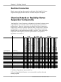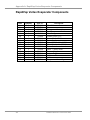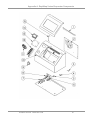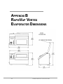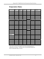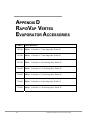
1
User’s Manual
RapidVap® Vertex™ Evaporator
Models
73200 Series
To receive important product updates,
complete your product registration card
online at register.labconco.com
Labconco Corporation
8811 Prospect Avenue
Kansas City, MO 64132-2696
800-821-5525, 816-333-8811
FAX 816-363-0130
E-MAIL [email protected]
HOME PAGE www.labconco.com
Please read the User’s Manual before operating the equipment.
Copyright © 2011 Labconco Corporation. All rights reserved.
The information contained in this manual and the accompanying products are copyrighted and all rights
reserved by Labconco Corporation. Labconco Corporation reserves the right to make periodic design
changes without obligation to notify any person or entity of such change.
Warranty
Labconco provides a warranty on all parts and factory workmanship. The warranty includes areas of
defective material and workmanship, provided such defect results from normal and proper use of the
equipment.
The warranty for all Labconco products will expire one year from date of installation or two years
from date of shipment from Labconco, whichever is sooner, except the following;
•
•
•
•
•
Purifier® Logic® Biological Safety Cabinets and PuriCare® Lab Animal Research Stations
carry a three-year warranty from date of installation or four years from date of shipment from
Labconco, whichever is sooner.
SteamScrubber® & FlaskScrubber® Glassware Washers carry a two-year warranty from date
of installation or three years from date of shipment from Labconco, whichever is sooner.
Blood Drawing Chairs carry a ten year warranty.
Carts carry a lifetime warranty.
Glassware is not warranted from breakage when dropped or mishandled.
This limited warranty covers parts and labor, but not transportation and insurance charges. In the
event of a warranty claim, contact Labconco Corporation or the dealer who sold you the product. If
the cause is determined to be a manufacturing fault, the dealer or Labconco Corporation will repair or
replace all defective parts to restore the unit to operation. Under no circumstances shall Labconco
Corporation be liable for indirect, consequential, or special damages of any kind. This statement may
be altered by a specific published amendment. No individual has authorization to alter the provisions
of this warranty policy or its amendments. Lamps and filters are not covered by this warranty.
Damage due to corrosion or accidental breakage is not covered.
Returned or Damaged Goods
Do not return goods without the prior authorization from Labconco. Unauthorized returns will not be
accepted. If your shipment was damaged in transit, you must file a claim directly with the freight carrier.
Labconco Corporation and its dealers are not responsible for shipping damages.
The United States Interstate Commerce Commission rules require that claims be filed with the delivery
carrier within fifteen (15) days of delivery.
Limitation of Liability
The disposal and/or emission of substances used in connection with this equipment may be governed by
various federal, state, or local regulations. All users of this equipment are required to become familiar
with any regulations that apply in the user’s area concerning the dumping of waste materials in or upon
water, land, or air and to comply with such regulations. Labconco Corporation is held harmless with
respect to user’s compliance with such regulations.
Contacting Labconco Corporation
If you have questions that are not addressed in this manual, or if you need technical assistance, contact
Labconco’s Customer Service Department or Labconco’s Product Service Department at 1-800-821-5525
or 1-816-333-8811, between the hours of 7:00 a.m. and 6:00 p.m., Central Standard Time.
Part #7324400, Rev. ECO F205
TABLE OF CONTENTS
CHAPTER 1: INTRODUCTION
Typographical Conventions
1
2
CHAPTER 2: PREREQUISITES
Electrical Requirements
Location and Exhaust Requirements
Nitrogen Supply Requirements
Space Requirements
Tools Required
3
4
4
4
4
4
CHAPTER 3: GETTING STARTED
Unpacking Your RapidVap Vertex Evaporator
RapidVap Vertex Evaporator Components
Setting Up Your RapidVap Vertex Evaporator
Sample Block
Nitrogen Gas Connection
Exhaust Port
Electrical Connection
Chemical Attack on RapidVap Vertex Evaporator Components
Solvent Safety Precautions
5
6
6
8
8
9
9
10
10
11
CHAPTER 4: USING YOUR RAPIDVAP VERTEX
EVAPORATOR
Planning
Loading Glassware into the RapidVap Vertex Evaporator
RapidVap Vertex Evaporator Controls
Operating the RapidVap Vertex Evaporator Controls
Operating the RapidVap Vertex Evaporator
Operational Notes
Interrupting a Cycle After it has Begun
13
14
14
14
15
19
20
20
CHAPTER 5: MAINTAINING YOUR RAPIDVAP VERTEX
EVAPORATOR
21
CHAPTER 6: TROUBLESHOOTING
22
APPENDIX A: RAPIDVAP VERTEX EVAPORATOR
COMPONENTS
25
APPENDIX B: RAPIDVAP VERTEX EVAPORATOR
DIMENSIONS
28
APPENDIX C: RAPIDVAP VERTEX EVAPORATOR
SPECIFICATIONS
Evaporation Rates
29
31
APPENDIX D: RAPIDVAP VERTEX EVAPORATOR
ACCESSORIES
32
DECLARATION OF CONFORMITY
33
CHAPTER 1
INTRODUCTION
Congratulations on your purchase of a Labconco RapidVap Vertex
Evaporator. Models are available for operation on 115V or 230V. Superior
evaporation rates are achieved by the unique blending of several gentle forces
on the sample. The vials containing the sample are held at an angle to
increase the surface area of the sample thereby increasing the evaporation
rate. A precisely controlled amount of thermal energy can be supplied to the
sample to heat it. Finally, a stream of nitrogen or dry gas is directed
downward onto the surface of the sample. This reduces the partial pressure
directly over the liquid to speed evaporation and helps remove the solvent as
it evaporates. In summary, the RapidVap Vertex Evaporator performance is
maximized by increasing the sample’s surface area, increasing temperature
and directing gas over the sample. The microprocessor provides excellent
regulation of the heater and reproducibility of protocols.
Product Service 1-800-522-7658
1
Chapter 1: Introduction
Typographical Conventions
Recognizing the following typographical conventions will help you
understand and use this manual:
•
•
•
!
)
•
•
2
Book, chapter, and section titles are shown in italic type (e.g., Chapter 3:
Getting Started).
Steps required to perform a task are presented in a numbered format.
Comments located in the margins provide suggestions, reminders, and
references.
Critical information is presented in boldface type in paragraphs that are
preceded by the exclamation icon. Failure to comply with the
information following an exclamation icon may result in injury to the user
or permanent damage to your RapidVap Vertex Evaporator.
Important information is presented in capitalized type in paragraphs that
are preceded by the pointer icon. It is imperative that the information
contained in these paragraphs be thoroughly read and understood by the
user.
Product Service 1-800-522-7658
CHAPTER 2
PREREQUISITES
Before you install your RapidVap Vertex Evaporator, you need to prepare
your site for installation. Carefully examine the location where you intend to
install your RapidVap Vertex Evaporator. You must be certain that the area is
level and of solid construction. In addition, an exhaust means must be
provided and a source of nitrogen or dry gas must be available. An electrical
source must be located near the installation site.
Carefully read this chapter to learn:
•
•
•
the electrical supply requirements.
the exhaust requirements.
the nitrogen supply requirements.
Refer to Appendix C: RapidVap Vertex Evaporator Specifications for
complete RapidVap Vertex Evaporator electrical and environmental
conditions, specifications and requirements.
Product Service 1-800-522-7658
3
Chapter 2: Prerequisites
Electrical Requirements
A dedicated electrical outlet is required. Minimum requirements for an outlet
is a 15 Amp circuit breaker or fuse for models rated at 115V (60 Hz) or an 8
Amp circuit breaker or fuse is required for 230V (50/60 Hz) models. 115V
models are equipped with a 15 Amp NEMA 5-15P plug. 230V models are
available with a NEMA 6-15P plug for use in the United States, a PS 1363
plug for use in the United Kingdom, a CEE 7/7 plug for use in Europe or a
CHI-10P plug for use in China. It may be necessary to remove the plug and
install a different plug to match the available receptacle if one of these
models does not meet your needs.
Location and Exhaust Requirements
!
The RapidVap Vertex Evaporator must be located within a fume hood if
hazardous or flammable solvents are used. In all cases, regardless of the
solvent used, it is recommended that the exhaust hose is vented into a fume
hood or other laboratory ventilation device.
Nitrogen Supply Requirements
The 1/4" I.D. hose on the rear of the RapidVap Vertex Evaporator should be
attached to a regulated source of nitrogen or other suitable gas. Pressure
must NOT exceed 50 psi. The nitrogen supply must be capable of 6.5 CFM
flow rate. A suitable barb or compression fitting must be supplied by the
user.
Space Requirements
Refer to Appendix B: RapidVap Vertex Evaporator Dimensions for
dimensional drawings of the RapidVap Vertex Evaporator.
Tools Required
Common hand tools are required to set up the RapidVap Vertex Evaporator.
A screwdriver or 5/16" socket is needed to attach hose clamps. A tubing
cutter or knife is needed to shorten exhaust hoses.
4
Product Service 1-800-522-7658
CHAPTER 3
GETTING STARTED
Now that the site for your RapidVap Vertex Evaporator is properly prepared,
you are ready to unpack, inspect, install, and test your RapidVap Vertex
Evaporator. Read this chapter to learn how to:
•
•
•
•
•
•
!
unpack and move your RapidVap Vertex Evaporator.
set up your RapidVap Vertex Evaporator.
connect the nitrogen source to your RapidVap Vertex Evaporator.
connect the electrical supply source to your RapidVap Vertex
Evaporator.
properly exhaust your RapidVap Vertex Evaporator.
solvent safety precautions.
The RapidVap Vertex Evaporator weighs over 35 lbs.
(16 Kg). The carton allows for lifting with a mechanical lift
truck or hand truck.
Product Service 1-800-522-7658
5
Chapter 3: Getting Started
Unpacking Your RapidVap Vertex
Evaporator
Carefully unpack your RapidVap Vertex Evaporator and inspect it for damage
that may have occurred in transit. If your RapidVap Vertex Evaporator is
damaged, notify the delivery carrier immediately and retain the entire shipment
intact for inspection by the carrier.
)
DO NOT RETURN GOODS WITHOUT THE PRIOR
AUTHORIZATION OF LABCONCO. UNAUTHORIZED
RETURNS WILL NOT BE ACCEPTED.
)
IF YOUR RAPIDVAP VERTEX EVAPORATOR WAS
DAMAGED IN TRANSIT, YOU MUST FILE A CLAIM
DIRECTLY WITH THE FREIGHT CARRIER. LABCONCO
CORPORATION AND ITS DEALERS ARE NOT
RESPONSIBLE FOR SHIPPING DAMAGES.
Do not discard the carton or packing material for your RapidVap Vertex
Evaporator until you have checked all of the components and installed and
tested the RapidVap Vertex Evaporator.
RapidVap Vertex Evaporator
Components
Locate the model of RapidVap Vertex Evaporator you received in the
following table. Verify that the components listed are present and undamaged.
Catalog #
Description
7320020
RapidVap Vertex Evaporator – 115V
Plus the Following:
Part #
Component Description
7913100
1966000
1334500
7324400
1533301
6
Exhaust Hose
Clamp
Power Cord NEMA 5-15P
User’s Manual
Tubing
Product Service 1-800-522-7658
The United
States
Interstate
Commerce
Commission
rules require
that claims be
filed with the
delivery
carrier within
fifteen (15)
days of
delivery.
Chapter 3: Getting Started
Catalog #
Description
7320030
RapidVap Vertex Evaporator – 230V EU
Plus the Following:
Part #
Component Description
7913100
1966000
1336100
7324400
1533301
Exhaust Hose
Clamp
Power Cord CEE 7/7
User’s Manual
Tubing
Catalog #
Description
7320035
RapidVap Vertex Evaporator – 230V UK
Plus the Following:
Part #
Component Description
7913100
1966000
1332600
7324400
1533301
Exhaust Hose
Clamp
Power Cord PS 1363
User’s Manual
Tubing
Catalog #
Description
7320037
RapidVap Vertex Evaporator – 230V China
Plus the Following:
Part #
Component Description
7913100
1966000
1332700
7324400
1533301
Exhaust Hose
Clamp
Power Cord CHI-10P
User’s Manual
Tubing
Catalog #
Description
7320040
RapidVap Vertex Evaporator – 230V US
Plus the Following:
Part #
Component Description
7913100
1966000
1338000
7324400
1533301
Exhaust Hose
Clamp
Power Cord NEMA 6-15P
User’s Manual
Tubing
Since users’ preference of sample size varies, the sample holding block is not
included with the RapidVap Vertex Evaporator. The correct size block must
be selected and ordered separately. Refer to Appendix D: RapidVap Vertex
Evaporator Accessories for block selection.
If you do not receive one or more of the components listed for your RapidVap
Vertex Evaporator, or if any of the components are damaged, contact
Labconco Corporation immediately for further instructions.
Product Service 1-800-522-7658
7
Chapter 3: Getting Started
Setting Up Your RapidVap Vertex
Evaporator
After you verify the RapidVap Vertex Evaporator components, move your
RapidVap Vertex Evaporator to the location where you want to install it.
Then, follow the steps listed below.
Sample Block
The RapidVap Vertex Evaporator was shipped without the sample block
installed. See Appendix D for available blocks. Vials must be snug in the holes
in the block. Select the appropriate block to fit the vials that will be used.
Make certain that the bottom of the chamber is clean and free of debris. The
sample block slides in on the two guides on the front and MUST rest securely
on the bottom. Make certain that the small .21" dia. temperature sensor hole is
in the upper left hand corner. Placing the block in the chamber improperly will
effect performance. Insert the tubular temperature sensor into the .21" dia. hole
to monitor upper block temperature. The actual sample temperature may be
monitored throughout a run by placing the sensor directly into a sample vial.
8
Product Service 1-800-522-7658
Chapter 3: Getting Started
Nitrogen Gas Connection
Mark the gas supply hose 3/4" (19 mm) from the end and push the hose into
the fitting in the back of the RapidVap Vertex Evaporator. Attach the other
end of the hose to user supplied nitrogen supply.
)
THE NITROGEN SUPPLY PRESSURE MUST NEVER BE
ALLOWED TO EXCEED 50 PSI (345 KPA).
Exhaust Port
If the RapidVap Vertex Evaporator is not located in a fume hood, attach one
end of the two inch diameter venting hose that is supplied with the RapidVap
Vertex Evaporator to the exhaust port on the rear of the unit. Clamp securely.
Route the other end to a fume hood or other laboratory ventilation device.
Product Service 1-800-522-7658
9
Chapter 3: Getting Started
Electrical Connection
Plug the power cord into the receptacle on the back of the RapidVap Vertex
Evaporator and plug the other end into a suitable wall power receptacle.
Chemical Attack on RapidVap Vertex
Evaporator Components
Your RapidVap Vertex Evaporator is designed to be chemical resistant to most
compounds that are commonly used in the concentration processes that are
performed in it. However, by necessity, the RapidVap Vertex Evaporator is
comprised of a number of different materials, some of which may be attacked
and degraded by certain chemicals. The degree of degradation is obviously
dependent on the concentration and duration of exposure. Some of the major
components of the RapidVap Vertex Evaporator that are susceptible to
degradation are as follows:
D
D
D D D D D D
D D D D D D
D
C
C
D
C
C
C
D
C
C
C
C
C
C
C
D D
D D C
C D
C
C
C
D
C
C
C
D
Toluene
Isoproponal
Methylene Chloride
C
C
C
D
C
C D
C- Moderate Degradation- Questionable Use
D- Severe Degradation-Infrequent use recommended-immediate thorough
cleaning required
10
Hexanes
D C
D C
D
D
Ethyl Acetate
Ethanol
Dimethyl Sulfoxide (DMSO)
Dimethyl Formamide
Chloroform
Acetonitrile
Acetone
Potassium Hydroxide
Solvents
C
C
D
D
D D D D
D D
D
D D
D
C
Ammonium Hydroxide
Trifluoroacetic Acid (TFA)
Sulfuric Acid 10%
Bases
Nitric Acid 20%
Hydrochloric Acid 20%
Hydrobromic Acid 20%
Formic Acid
MATERIAL
Polyamid (Nylon)
Polyamid (Nylon)
Polypropylene
Polyethylene
Polyethylene
UMHW Polyethylene
PVC
Epoxy Coated Alum.
Aluminum
Stainless Steel
Stainless Steel
Epoxy Coated Steel
Glass
Boric Acid
COMPONENT
Elbow N2
Blower Impeller
Blower Housing
Exhaust Hose
N2 Supply Hoses
Block Guides
Window Seal
Lid
Chamber & Block
Nozzle N2
Exhaust Fitting
Ducting
Window
Acetic Acid 20%
Acids
Product Service 1-800-522-7658
C
C
C
C
D
Chapter 3: Getting Started
•
Glass lids are suitable for use with all common compounds.
When using compounds in the RapidVap Vertex Evaporator that are hostile to
the materials of construction, it is imperative that the equipment is properly
maintained.
•
After each run, clean up all residues, spills, and materials that might have
splashed in the chamber using agents suitable for the substance involved.
With prudent maintenance your RapidVap Vertex Evaporator will provide many
years of service. Warranty on the affected parts will be void if maintenance has
obviously been neglected. If you have questions about using specific compounds
in your RapidVap Vertex Evaporator, contact Labconco Technical Service at
1-800-821-5525 or 816-333-8811 or e-mail [email protected].
)
Solvent Safety Precautions
The RapidVap Vertex Evaporator is not classified as “explosion proof.” It has
been designed with safety as a primary consideration and should be used in a
prudent manner using “good laboratory practices.” It has been designed for
use with compounds as described in the United States National Electrical Code
Class I, Group D. The block that holds the sample tubes may be programmed
to run as hot as 100°C, however, the heater element may normally run at
135°C. A thermal fuse limits the heater to a maximum temperature of 152°C.
It is important that the solvents used are compatible with these temperatures.
!
Do not evaporate solvents that have an autoignition
temperature below 180°C. Do not evaporate solvents that
are classified as Group A, B, or C by the National Electrical
Code. Evaporate only non-flammable or Group D solvents
with autoignition temperatures 180°C or above. Use of
other compounds could cause an explosion.
Solvents used in the RapidVap Vertex Evaporator may be
flammable or hazardous. Use extreme caution and keep
sources of ignition away from the solvents. When using
flammable or hazardous solvents, the RapidVap Vertex
Evaporator should be operated inside a fume hood.
If a sample is spilled in the chamber it must immediately be
cleaned up.
Hazardous materials such as strong acids or bases,
radioactive substances and volatile organics, must be
handled carefully and promptly cleaned up if spilled.
Product Service 1-800-522-7658
11
Chapter 3: Getting Started
Several components of the RapidVap Vertex Evaporator
which are located inside the chamber are made of stainless
steel or aluminum which can be attacked by acids. Use of
acids such as trifluoroacetic acid can result in degradation
of the product. Use care when using aggressive liquids
which can damage the RapidVap Vertex Evaporator and
thoroughly clean the RapidVap Vertex Evaporator after
each use. Contact Labconco before evaporating acids.
WARNING: The disposal of substances used in connection
with this equipment may be governed by various Federal,
State or local regulations. All users of this equipment are
urged to become familiar with any regulations that apply in
the user’s area concerning the dumping of waste materials
in or upon water, land or air and to comply with such
regulations.
12
Product Service 1-800-522-7658
CHAPTER 4
USING YOUR RAPIDVAP
VERTEX EVAPORATOR
After your RapidVap Vertex Evaporator has been installed as detailed in
Chapter 3: Getting Started, you are ready to begin using your RapidVap
Vertex Evaporator. Read this chapter to learn how to:
•
•
•
•
•
set operating parameters.
operate the controls.
properly select and position glassware inside your RapidVap Vertex
Evaporator.
understand the display.
interrupt a cycle after it has begun.
!
Do not use the RapidVap Vertex Evaporator in a manner
not specified by the manufacturer (refer to Appendix C:
RapidVap Vertex Evaporator Specifications). The electrical
protection properties of the RapidVap Vertex Evaporator
may be impaired if the RapidVap Vertex Evaporator is
used inappropriately.
Product Service 1-800-522-7658
13
Chapter 4: Using Your RapidVap Vertex Evaporator
Planning
Thoroughly understand procedures and the equipment operation prior to
beginning work. The unique performance of the RapidVap Vertex
Evaporator is dependent upon the proper balance of heat and nitrogen flow.
If the proper balance is not established, it is possible to damage or lose a
portion of the sample. Therefore, if you are unfamiliar with the RapidVap
Vertex Evaporator or are attempting a new protocol, it may be helpful to
make a trial run that is void of the sample you are attempting to concentrate.
Select the size of the sample tube so it is compatible with the block. Tubes
should not be loose in the block. Blocks are available with holes for various
size tubes.
Loading Glassware Into the RapidVap
Vertex Evaporator
There are 5 control valves that control nitrogen to the 5 horizontal rows of
nozzles. Samples should be positioned in complete rows as much as possible.
This will minimize the number of rows of nozzles and reduce gas consumption.
RapidVap Vertex Evaporator Controls
The control panel for the RapidVap Vertex Evaporator is shown below with a
description about their function.
14
Product Service 1-800-522-7658
Chapter 4: Using Your RapidVap Vertex Evaporator
Nitrogen Control Valves – Used to turn nitrogen flow ON or OFF to the
nozzles above the sample vials. The top valve controls the 10 nozzles on the
top row. The second valve controls the second row of 10 nozzles. The third
valve controls the middle row of 10 nozzles. The fourth valve controls the
fourth row of 10 nozzles. The bottom valve controls the bottom row of 10
nozzles. Push the lever to the right to turn nitrogen flow ON.
Nitrogen Pressure Regulator – Used to adjust the gas pressure and gas flow
rate to the nozzles. To adjust the gas pressure to the nozzles, the gas supply
must be connected. Open all of the control valves that will be used during the
run. Turn the unit ON and press Run, the main gas supply valve will open.
Pull the knob of the Pressure Regulator out and rotate the knob clockwise to
increase pressure, counter clockwise to decrease the pressure. The operating
pressure is displayed on the knob. Once the pressure is set push the regulator
knob in and press Stop.
The pressure can be adjusted at any time during the run. Also note that
opening or closing any of the Nitrogen Control Valves without adjusting the
pressure will change the flow rate at each nozzle.
The flow rate of gas is approximately 1 cfm (28.3 L/min) per row of 10
nozzles when pressure is set at 24 PSI (165 KPA).
Digital Display – The touch screen LCD is used to control run time and
temperature, preheat temperature and other functions as described below.
Operating the RapidVap Vertex Evaporator
Controls
When the power switch on the left hand side is turned ON the opening
display will show:
BLOCK
SAMP
52
51
°C
Run
Pre Heat
Prog
(In all diagrams, the numbers are just examples and will vary)
Press open area above °C or °F symbol to change the degree display to show
°C or °F. All parameters that are entered will be remembered in the
microprocessor memory and will remain entered until reset.
Product Service 1-800-522-7658
15
Chapter 4: Using Your RapidVap Vertex Evaporator
Program:
To enter a new program while in the opening display press “PROG” and the
display will show:
PROG
TEMP
TIME
1
35
62
Back
Run
Press “Back” to return to the opening display, press “Run” to start this
program. If the program, temperature or time needs to be changed, press
either “PROG,” “TEMP” or “TIME.” The display will show:
PROG
TEMP
TIME
3
67
74
Back
Up
Down
Run
Ten different programs may be stored and then later recalled. Press “PROG”
or “TEMP” or “TIME” and the word will start to flash. Press “Up” or
“Down” to change the value. Another word may be selected and the value
under the word may be changed by pressing “Up” or “Down.” Press either
“Run” to begin the run or press “Back” to return to the opening display.
If “TIME” is set to ON, the program will run continually until turned off by
pressing “STOP” or “PAUSE.”
16
Product Service 1-800-522-7658
Chapter 4: Using Your RapidVap Vertex Evaporator
Pre-Heat:
If it is necessary to pre-heat the chamber before starting a run, press Pre-Heat.
This display will show:
BLOCK
SAMP
SET
TEMP
52
51
85
Stop
Press “Stop” to return to the opening display and turn off the heater or press
“SET TEMP” to set the pre-heat temperature. The display will show:
BLOCK
SAMP
SET
TEMP
52
51
90
Stop
Up
Down
The “SET TEMP” will flash. Then press “Up” or “Down” to adjust the block
temperature. In this example 52 is the temperature of the sample block, 51 is
the upper block or sample temperature. The heater will heat the block and
maintain it at the set temperature. Press “Stop” to turn the heater off and to
return to the opening display.
Product Service 1-800-522-7658
17
Chapter 4: Using Your RapidVap Vertex Evaporator
Run:
To re-run the last program while in the opening display, press “Run.” The
heater will be powered, the master nitrogen control valve will open, the time
will start to count down and the display will show:
BLOCK
SAMP
TIME
52
51
124
Pause
Stop
Prog
In this example, 52 indicates the sample block temperature, 51 indicates the
upper block temperature or sample temperature, and 124 indicates the time
remaining for this programmed run.
Press “Pause” to temporarily halt the run.
BLOCK
SAMP
TIME
57
55
67
Re-Start
Stop
Prog
The word “Pause” will be replaced with “Re-Start” which when pressed will
continue the run from the point where it was paused.
Press “Stop” to halt the run entirely. The display will show the opening
screen.
18
Product Service 1-800-522-7658
Chapter 4: Using Your RapidVap Vertex Evaporator
If “PROG” is pressed in the middle of a run, the display will show the
programmed parameters for that run.
PROG
TEMP
TIME
3
84
103
Back
Parameters may not be altered. Press “Back” to return to the operating
screen. Then if the run parameters must be altered, press “Stop” and reprogram the display as described below:
Operating the RapidVap Vertex
Evaporator
1. Turn the power switch ON.
2. Turn the nitrogen supply on.
3. Select a program or set the temperature and time parameters. Solvents
will evaporate quicker at warmer temperatures. Use care to avoid
damaging the samples.
4. Preheat the block if desired.
5. Open a nitrogen control valve for the row of nozzles to be used. Make
sure the lid is closed.
6. Set the nitrogen pressure by first selecting the rows of nozzles to be used
during the run. Then press run to open the gas supply valve. Pull out the
regulator knob and turn the knob until the desired pressure is displayed in
the center of the knob. Evaporation rates will be higher at increased
pressure. However, splashing of the sample may occur. It is advisable to
perform a set up run void of analytes to determine the optimal pressure
for the tube and sample size being used. Push the knob in. Turn off the
gas supply by pressing Stop or open the lid.
7. Place samples in vials and place vials into the block. If monitoring actual
sample temperature, place the temperature probe into sample vial making
sure the wires do not cover any nozzles. Close the lid.
8. Press “Run” on the display.
9. At the end of the programmed time the heater and nitrogen flow will turn
off. If the display time was set to ON, the run continues until “Stop” or
“Pause” is pressed.
10. The lid may be opened and samples removed. Use caution because the
block and samples may be hot.
Product Service 1-800-522-7658
19
Chapter 4: Using Your RapidVap Vertex Evaporator
Operational Notes
The LCD display conveys various pieces of information. When the
RapidVap Vertex Evaporator is turned ON, the RapidVap Vertex Evaporator
will return to the same mode (RUN or STOP) that it was in when the power
was turned off. If the RapidVap Vertex Evaporator was in the RUN mode
when the power was turned OFF, when the power is turned ON, the
RapidVap Vertex Evaporator will attempt to return to the programmed set
points.
If the previous run is to be duplicated, it is important to press the “Stop”
button prior to pressing “Run.” This will reset the timer back to the
programmed set point. Without pressing the program set point button, the
time will not be reset and will continue to count down from the time at which
it was stopped.
Interrupting a Cycle After it Has Begun
At any time during a run, the cycle may be stopped by pressing the “Pause”
button. This shuts off the nitrogen flow and pauses the timer, but the heater
remains active. If it is necessary to re-start the RapidVap Vertex Evaporator,
close the lid and press “RESTART.” The RapidVap Vertex Evaporator will
resume operation at the same set point parameters and the timer will continue
to count down from the time at which the RapidVap Vertex Evaporator was
paused.
20
Product Service 1-800-522-7658
CHAPTER 5
MAINTAINING YOUR
RAPIDVAP VERTEX
EVAPORATOR
Under normal operation, the RapidVap Vertex Evaporator requires little
maintenance. The following maintenance schedule is recommended:
As needed:
1. Clean up all spills; remove liquids from chamber.
2. Clean lid and viewing window using soft cloth, sponge or chamois and a
mild, non-abrasive soap or detergent.
3. Clean block using non abrasive soap or detergent.
Monthly:
1. The rubber components on the RapidVap Vertex Evaporator may
eventually deteriorate and require replacement. The effective life of
rubber parts depends upon both their usage and the surrounding
environment. Check all rubber hoses and gaskets and replace any that
show signs of hardening, permanent set or deterioration.
2. Using a soft cloth, sponge or chamois and a mild, non-abrasive soap or
detergent, clean the lid and viewing window.
3. Using a soft cloth, sponge, or chamois and a mild, non-abrasive soap or
detergent, clean the exterior surfaces of the unit. Liquid spray cleaners
and polishes may be used on the exterior surfaces. Do not use solvents to
remove stains from the exterior surfaces as they may damage the finish.
4. Blocks should be cleaned
Product Service 1-800-522-7658
21
CHAPTER 6
TROUBLESHOOTING
Refer to the following if your RapidVap Vertex Evaporator fails to operate
properly. If the suggested corrective actions do not solve your problem,
contact Labconco for additional assistance.
PROBLEM
CAUSE
CORRECTIVE ACTION
Unit will not operate
Unit not connected to
electrical power
Connect unit to proper electrical
receptacle.
Circuit breaker blown
Correct electrical problem and reset
circuit breaker by pressing button.
Lid open
Close lid.
Vent hose exhausting into lab
area
Redirect hose to fume hood.
Inoperable blower
Replace blower.
Solvent in bottom of
chamber
Gas pressure too high
Reduce pressure.
Poor recovery rates
Sample going to dryness
Program time to prevent dryness.
Sample splashing out of tube
Decrease Nitrogen pressure.
Heat setting is too high
Decrease heat.
Sample odor in lab
22
Product Service 1-800-522-7658
Chapter 6: Troubleshooting
PROBLEM
CAUSE
CORRECTIVE ACTION
Evaporation rate is
reduced
Gas supply depleted
Replenish gas supply.
Heater inoperable
Contact Labconco.
Gas depleted
Install new supply of gas.
Sample position not activated
Activate position per operating
instructions.
Nozzle clogged
Unplug nozzle with fine wire.
Valve inoperable
Contact Labconco
Valve inoperable
Contact Labconco
Control inoperable
Contact Labconco
No gas flow
Gas flows
continuously
Product Service 1-800-522-7658
23
Chapter 6: Troubleshooting
24
Product Service 1-800-522-7658
APPENDIX A
RAPIDVAP VERTEX
EVAPORATOR COMPONENTS
The following pages list components that are available for your RapidVap
Vertex Evaporator. The parts shown are the most common replacement
parts. If other parts are required, contact Product Service.
Product Service 1-800-522-7658
25
Appendix A: RapidVap Vertex Evaporator Components
RapidVap Vertex Evaporator Components
Item
1
2
3
4
5
6A
6B
7
8A
8B
9
10
11
12
13
14
15
26
Quantity
5
1
1
1
2
1
1
1
1
2
1
1
1
5
1
1
1
Part No.
7320400
7323700
7353300
7325100
1544600
7321800
7321801
3823803
1289310
1289306
1302300
7321400
7321900
7322500
7323100
7323000
7355301
Description
Manifold
Blower
Temperature Sensor Lower
Over Temperature Cut Out
Inlet Fitting
Control Valve 115V
Control Valve 230V
Power Supply
Circuit Breaker 10A (115V)
Circuit Breaker 6A (230V)
Power Switch
Label – Control Panel
Pressure Regulator
Valve – Toggle
PCB
LCD
Temperature Sensor Upper
Product Service 1-800-522-7658
Appendix A: RapidVap Vertex Evaporator Components
Product Service 1-800-522-7658
27
APPENDIX B
RAPIDVAP VERTEX
EVAPORATOR DIMENSIONS
28
Product Service 1-800-522-7658
APPENDIX C
RAPIDVAP VERTEX
EVAPORATOR
SPECIFICATIONS
This Appendix contains technical information about the RapidVap Vertex
Evaporator including specifications, environmental operations conditions,
wiring diagrams and evaporation rates.
Electrical Specifications
•
•
•
•
•
Nominal amperage for 115V RapidVap Vertex Evaporator (model
7320020): 8A
Nominal amperage for 230V RapidVap Vertex Evaporator Vacuum
(models 7320030, 7320035, 7320037, 7320040): 4A
Frequency (all models): 50/60 Hz
Phase: Single
Heater power: 900 watts
Environmental Conditions
•
•
•
•
•
•
Indoor use only.
Maximum altitude: 6562 feet (2000 meters).
Ambient temperature range: 41° to 104°F (5° to 40°C).
Maximum relative humidity: 80% for temperatures up to 88°F
(31°C), decreasing linearly to 50% relative humidity at 104°F (40°C).
Main supply voltage fluctuations not to exceed ±10% of the nominal
voltage.
Transient overvoltages according to Installation Categories II
(Overvoltage Categories per IEC 1010). Temporary voltage spikes on
the AC input line that may be as high as 1500V for 115V models and
2500V for 230V models are allowed.
Product Service 1-800-522-7658
29
Appendix C: RapidVap Vertex Evaporator Specifications
•
Used in an environment of Pollution degrees 2 (i.e., where normally
only non-conductive atmospheres are present). Occasionally,
however, a temporary conductivity caused by condensation must be
expected, in accordance with IEC 664.
Nitrogen Consumption
30
•
Gas flow RapidVap Vertex Evaporator with 10 active nozzles:
0.74 SCFM @ 15 psi (21 L/min @ 103 KPA)
1.00 SCFM @ 24 psi (28.3 L/min @ 165 KPA)
•
Gas flow RapidVap Vertex Evaporator with 50 active nozzles:
4.5 SCFM @ 20 psi (127 L/min @ 138 KPA)
5.00 SCFM @ 24 psi (141.5 L/min @ 165 KPA)
Product Service 1-800-522-7658
Appendix C: RapidVap Vertex Evaporator Specifications
Evaporation Rates
Solvent
Tube Size
(mm)
12 x 75
12 x 75
12 x 75
12 x 75
Number of
Samples
10
10
10
10
Sample
Size (ml)
2
2
2
2
35
45
60
80
N2 Pressure
PSI
16
16
16
16
*Avg. Time to
Dry (min.)
< 19
<15
<11
<8
Methanol
12 x 75
12 x 75
12 x 75
12 x 75
12 x 75
20 x 150
10
10
10
10
50
10
2
2
2
2
2
10
35
45
60
80
80
52
24
24
24
24
24
37
<12
<10
<7
<6
<6
<42
Water
12 x 75
12 x 75
12 x 75
12 x 75
20 X 150
20 X 150
10
10
10
10
10
50
2
2
2
2
4
4
45
60
80
100
100
100
24
24
24
24
24
24
<125
<80
<40
<25
<60
<64
Toluene
12 x 75
12 x 75
12 x 75
12 x 75
10
10
10
10
2
2
2
2
35
45
60
80
16
16
16
16
<24
<18
<13
<9
Methylene
Chloride
12 x 75
12 x 75
20 x 150
10
10
10
2
2
10
35
45
38
20
22
37
<8
<7
<22
Hexane
20 x 150
10
10
52
37
<11
Ethyl Acetate
20 x 150
10
10
52
37
<22
Acetonitrile
Temp (C)
*Time to Dry is the time for samples in each of the indicated number of
sample tubes to evaporate. The time to dry for any individual sample tube
may be considerably longer or shorter.
Product Service 1-800-522-7658
31
APPENDIX D
RAPIDVAP VERTEX
EVAPORATOR ACCESSORIES
PART #
DESCRIPTION
7324100
Block. 10 mm dia. x 75 mm long tubes. Holds 50.
7321200
Block. 12 mm dia. x 75 mm long tubes. Holds 50.
7321300
Block. 13 mm dia. x 100 mm long tubes. Holds 50.
7321600
Block. 16 mm dia. x 125 mm long tubes. Holds 50.
7322000
Block. 20 mm dia. x 150 mm long tubes. Holds 50.
7322800
Block. 28 mm dia. x 95 mm long tubes. Holds 18.
7322801
Block. 28 mm dia. x 140 mm long tubes. Holds 18.
32
Product Service 1-800-522-7658
Product Service 1-800-522-7658
33