1
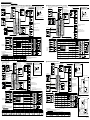
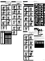
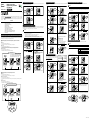
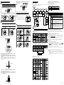
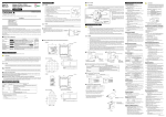
6. Terminal Wiring Diagrams
NOTE
Do not use unassigned terminals as relay terminals.
■ UT450 Standard Type (Model UT450-0䊐 or UT450-3䊐) or Heating/Cooling Type(Model UT450-2䊐)
*Wiring can only be carried out for controllers with
24 V DC loop power supply.
24 V DC loop
power supply
21.6-28.0VDC
(30 mA DC max.)
RS-485 communication * Wiring can only be carried out
23 SDB(+)
24
+ 43
SDA(-)
- 44
Relay contact output
1
NO
2
COM
3
N
1
41
31
21
11
2
42
32
22
12
3
43
33
23
13
4
44
34
24
14
5
9
45
35
25
13 -
13 -
13 B
46
36
26
16
7
47
37
27
17
8
48
38
28
18
9
49
39
29
19
10
50
40
30
20
Control output
Current/voltage
pulse output
16 +
17 -
Note:Select this option
from the OT
parameter.
Alarm-1 output
Relay
No function
AUTO when DI1=ON
MAN when DI1=OFF
AUTO when DI1=ON STOP when DI1=ON
MAN when DI1=OFF RUN when DI1=OFF
When switching target
SP 1 to 4:
1.SP2.SP3.SP 4.SP
No function
STOP when DI2=ON
RUN when DI2=OFF
2.SP when DI2=ON 2.SP when DI2=ON
1.SP when DI2=OFF 1.SP when DI2=OFF
DI1 OFF ON OFF ON
COM 7
Common
Alarm-4 output
AL4 34
No function
No function
* If all of the contact inputs are set to OFF,
the controller uses the immediately
preceding target setpoint.
No function
Common
Remote when R/L=ON
Local when R/L=OFF
Remote when R/L=ON
Local when R/L=OFF
Common
Common
COM 35
Common
Relay contact rating: 240 V AC, 1 A
30 V DC, 1 A (resistance load)
Transistor contact rating: 24 V DC, 50 mA
* OT is a setup parameter.
You can change the settings of the parameter OT to change the
control output type.
See Initial Settings User’s Manual , for more information.
COM
50
0%
L
11 A
12 +
250 Ω 4-20mA
12 b
26
RDA(-)
27
SG
21 +
22 -
46
45
100%
13 -
13 B
Specify in a range of
1-5 V DC, 0-2 V DC,
or 0-10 V DC.
mV/V input
Before carrying out wiring, turn off the power
to the controller and check that cables to be
connected are not alive with a tester or the like
because there is a possibility of electric shock.
9
1
41
31
21
11
2
42
32
22
12
3
43
33
23
13
4
44
34
24
14
5
45
35
25
15
6
46
36
26
16
7
47
37
27
17
8
48
38
28
18
9
49
39
29
19
10
50
40
30
20
13 -
Retransmission output
DI1
14 +
4-20 mA DC
15 -
Load resistance: 600 Ω or less
15 V DC loop power supply
14 +
DI2
+5V
STOP when DI3=ON AUTO when DI3=ON STOP when DI3=ON
RUN when DI3=OFF MAN when DI3=OFF RUN when DI3=OFF
AUTO when DI4=ON
No function
No function
MAN when DI4=OFF
DI3 40
+5V
DI4 39
+5V
No function
No function
No function
DI5 38
+5V
No function
No function
No function
DI6 37
Common
Common
Common
COM 20
DI2 OFF OFF ON ON
DI3
DI4
DI6
Common
40
39
38
37
* Alarm-4
output is
optional
function
COM
20
+5V
Remote when R/L=ON Remote when R/L=ON Remote when R/L=ON
Local when R/L=OFF Local when R/L=OFF
Local when R/L=OFF
R/L 28
Common
DI5
Alarm-1 output
18
R/L
COM
COM 30
AL1 6
14.5-18.0VDC
(21 mA DC max.)
Correspondence between parameter DIS and external contact input functions
UT
When DIS=0
When DIS=1 (Factory-shipped setting)
No function
AUTO when DI1=ON
MAN when DI1=OFF
AUTO when DI1=ON STOP when DI1=ON
MAN when DI1=OFF RUN when DI1=OFF
When switching target
SP 1 to 4:
1.SP2.SP3.SP 4.SP
No function
STOP when DI2=ON
RUN when DI2=OFF
2.SP when DI2=ON 2.SP when DI2=ON
1.SP when DI2=OFF 1.SP when DI2=OFF
DI1 OFF ON OFF ON
AL2 5
Alarm-2 output
Alarm-3 output
AL3 4
Common
COM 7
Alarm-4 output
AL4 34
DI3 ON OFF ON OFF ON OFF ON OFF
DI4 OFF ON ON OFF OFF ON ON OFF
DI5 OFF OFF OFF ON ON ON ON OFF
No function
COM 35
Contact rating: 12 V DC, 10 mA or more
When DIS=4
DI2 OFF OFF ON ON
Contact
UT
DI1 19
+5V
DI2 18
+5V
No function
No function
Common
Common
Remote when R/L=ON
Local when R/L=OFF
Remote when R/L=ON
Local when R/L=OFF
Remote when R/L=ON
Local when R/L=OFF
+5V
DI3
+5V
DI4
+5V
+5V
OT=1
OT=2
OT=3
Time proportional control
Relay output (terminals 1 , 2 and 3 )
Time proportional control
Voltage pulse output (terminals 16 and 17 )
Current output
(terminals 16 and 17 )
On-off control
Relay output (terminals 1 , 2 and 3 )
Common
NOTE: External Contact Input
If the power is turned on when the external contact input is OFF, the
mode (SPN, R/L, or A/M) existing before the power is turned off will be
continued. (except for RUN/STOP)
Note: Select this option from the OT parameter.
Cooling-side control Cooling-side control
output
output
Current/voltage pulse output
Relay contact output
NC
4-20 mA DC,
voltage pulse
(12 V)
+ 46
NO
49
- 47
COM
50
Contact rating: 250 V AC, 3 A
30 V DC, 3 A (resistance load)
L
N
8
CAUTION
Before carrying out wiring, turn off the power
to the controller and check that cables to be
connected are not alive with a tester or the like
because there is a possibility of electric shock.
9
25 RDB(+)
RDA(-)
21 +
SG
22 -
11 A
mV/V input
31
21
11
42
32
22
12
43
33
23
13
44
34
24
14
13 -
25
15
6
46
36
26
16
7
47
37
27
17
8
48
38
28
18
9
49
39
29
19
50
40
30
16 +
17 -
20
Relay
AL2 5
Alarm-3 output
AL3 4
14 +
No function
AUTO when DI1=ON
MAN when DI1=OFF
COM 7
Transistor
No function
Alarm-4 output
AL4 34
Common
COM 35
No function
No function
Relay contact rating: 240 V AC, 1 A
30 V DC, 1 A (resistance load)
Transistor contact rating: 24 V DC, 50 mA
L
N
NOTE: External Contact Input
If the power is turned on when the external contact input is OFF, the
mode (SPN, R/L, or A/M) existing before the power is turned off will be
continued. (except for RUN/STOP)
* OT is a setup parameter.
You can change the settings of the parameter OT to change the
control output type.
See Initial Settings User’s Manual , for more information.
Remote when R/L=ON
Local when R/L=OFF
1.SP2.SP 3.SP4.SP 5.SP6.SP7.SP 8.SP
DI5 OFF OFF OFF ON ON ON ON OFF
No function
DI6 OFF OFF OFF OFF OFF OFF OFF ON
* If all of the contact inputs are set to OFF, the controller
uses the immediately preceding target setpoint.
No function
DI1 OFF ON OFF ON
DI2 OFF OFF ON ON
UT
DI1 19
DI2 18
No function
No function
No function
No function
Common
Common
Remote when R/L=ON Remote when R/L=ON Remote when R/L=ON
Local when R/L=OFF Local when R/L=OFF
Local when R/L=OFF
Remote when R/L=ON
Local when R/L=OFF
Common
Common
DI5 38
Contact
+5V
Transistor contact
DI1
+5V
DI2
Common
RDA(-)
+5V
DI3
+5V
DI4
+5V
+5V
DI5
DI6
DI6 37
27
SG
Common
R/L 28
COM 30
COM
Note:Select this option from
the OT parameter.
*Time proportional PID relay contact
output is configured at factory
before shipment.
R/L
COM
COM 30
28
30
Contact rating: 12 V DC, 10 mA or more
8
Before carrying out wiring, turn off the power
to the controller and check that cables to be
connected are not alive with a tester or the like
because there is a possibility of electric shock.
9
Alarm-1 output
40
39
AL1 6
Alarm-2 output
AL2 5
Alarm-3 output
AL3 4
Common
COM 7
38
37
11 A
Specify in a range of
1-5 V DC, 0-2 V DC,
or 0-10 V DC.
12 +
12 +
250 Ω 4-20mA
12 b
13 -
13 -
13 B
1
21
11
2
22
12
3
23
13
4
24
14
5
25
15
6
26
16
7
27
17
8
28
18
9
29
30
15 V DC Power Supply Wiring to Two-wire Sensor
Retransmission output
* PV retransmission is configured
at factory before shipment.
Control output
Current/voltage
pulse output
16 +
19
17 -
4-20 mA DC
15 -
Note:Select this
option from
the OT
parameter.
14 +
20
15 -
* If 15 V DC loop power supply
is used, retransmission output
cannot be used.
14.5-18.0VDC
(21 mA DC max.)
UT
No function
No function
AUTO when DI1=ON
MAN when DI1=OFF
STOP when DI2=ON
RUN when DI2=OFF
Common
No function
When DIS=2
When DIS=3
When switching target
SP 1 to 4:
1.SP 2.SP3.SP 4.SP
2.SP when DI2=ON 2.SP when DI2=ON
1.SP when DI2=OFF 1.SP when DI2=OFF
DI1 OFF ON OFF ON
DI2 OFF OFF ON ON
Common
Common
STOP when DI3=ON AUTO when DI3=ON
RUN when DI3=OFF MAN when DI3=OFF
No function
No function
Remote when R/L=ON
Local when R/L=OFF
Remote when R/L=ON
Local when R/L=OFF
When DIS=4
AUTO when DI1=ON STOP when DI1=ON
MAN when DI1=OFF RUN when DI1=OFF
Remote when R/L=ON
Local when R/L=OFF
Remote when R/L=ON
Local when R/L=OFF
Common
Common
Common
UT
DI1 19
+5V
Common
STOP when DI3=ON
RUN when DI3=OFF
DI3 29
Transistor contact
DI1
+5V
DI2
DI2 18
COM 20
OT=5
OT=6
OT=7
OT=8
OT=9
OT=10
OT=11
OT=12
Heating side: Voltage pulse output
(terminals 16 and 17 )
Cooling side: Relay output
(terminals 48 , 49 and 50 )
Heating side: Current output
(terminals 16 and 17 )
Cooling side: Relay output
(terminals 48 , 49 and 50 )
Heating side: Relay output
(terminals 1 , 2 and 3 )
Cooling side: Voltage pulse output
(terminals 46 and 47 )
Heating side: Voltage pulse output
(terminals 16 and 17 )
Cooling side: Voltage pulse output
(terminals 46 and 47 )
Heating side: Current output
(terminals 16 and 17 )
Cooling side: Voltage pulse output
(terminals 46 and 47 )
Heating side: Relay output
(terminals 1 , 2 and 3 )
Cooling side: Current output
(terminals 46 and 47 )
Heating side: Voltage pulse output
(terminals 16 and 17 )
Cooling side: Current output
(terminals 46 and 47 )
Heating side: Current output
(terminals 16 and 17 )
Cooling side: Current output
(terminals 46 and 47 )
14
COM
* OT is a setup parameter.
You can change the settings of the parameter OT to change the control output type.
See Initial Settings User’s Manual , for more information.
19
* Wiring can only be carried out for controllers with 24 V DC
loop power supply.
18
24 V DC Power Supply Wiring to Two-wire Sensor
20
12
DI3
+5V
COM 30
Loop power
supply
14.5 to
18.0 V DC
Note: Connecting a 100 resistor to the terminals is optional.
Model: X010-100-2 (resistor with M3.5 crimp-on terminal lugs)
+5V
Remote when R/L=ON
R/L 28
Local when R/L=OFF
Common
Contact
R/L
COM
Contact rating: 12 V DC, 10 mA or more
NOTE: External Contact Input
If the power is turned on when the external contact input is OFF,
the mode (SPN, R/L, or A/M) existing before the power is turned off will be
continued. (except for RUN/STOP)
OT=4 (factory-set default)
Two-wire transmitter
4-20mADC
Correspondence between parameter DIS and external contact input functions
When DIS=0 When DIS=1 (Factory-shipped setting)
30
Heating side: Relay output
(terminals 1 , 2 and 3 )
Cooling side: Relay output
(terminals 48 , 49 and 50 )
13
Load resistance: 600 Ω or less
15 V DC loop power supply
4-20 mA DC,
voltage pulse
(12 V)
PV input
0.4 to 2.0 V DC signal
15
Common
Correspondence between parameter OT and heating-side/cooling-side output types
12
External
resistor 100
(Note)
14 +
* DIS is a setup parameter.
Changing DIS setpoint allows you to change the function of external contact input.
Relay contact rating: 240 V AC, 1 A
30 V DC, 1 A (resistance load)
Transistor contact rating: 24 V DC, 50 mA
28
Note: Connecting a 250 Ω resistor to the terminals is
optional.
Model: X010-250-2 (resistor with M3.5 crimp-on terminal
lugs)
13 -
10
Allowable range: 100 to 240 V AC (10%)
(free voltage)
50/60 Hz shared
18
set the PV input type to 1-5 V DC (setpoint “41”).
12 +
Contact rating: 12 V DC, 10 mA or more
The control output types, “relay output” and “voltage pulse output” shown in the table above refer to those of time proportional control.
To change the type to a relay output for on-off control, select “Relay Terminals” and change the setpoint of the proportional band to “0.”
37
* When receiving 4-20 mA DC current signals,
RTD input
+5V
R/L
38
䊏 Receiving 4-20 mA DC Current
Signals by the Controller
mV/V input
Alarm output
20
COM 20
Common
Common
Common
TC input
Default: 1-5 V DC
10
19
COM
Common
Common
Common
When DIS=4
STOP when DI3=ON AUTO when DI3=ON STOP when DI3=ON DI3 40
RUN when DI3=OFF MAN when DI3=OFF RUN when DI3=OFF
AUTO when DI4=ON
No function
DI4 39
No function
MAN when DI4=OFF
DI3 ON OFF ON OFF ON OFF ON OFF
DI4 OFF ON ON OFF OFF ON ON OFF
No function
When DIS=3
26
22 -
CAUTION
Power supply
14.5-18.0VDC
(21 mA DC max.)
2.SP when DI2=ON 2.SP when DI2=ON
1.SP when DI2=OFF 1.SP when DI2=OFF
When switching target SP 1 to 8:
3
* If 15 V DC loop power supply is used,
retransmission output cannot be used.
switching target
AUTO when DI1=ON STOP when DI1=ON When SP
1 to 4:
MAN when DI1=OFF RUN when DI1=OFF
1.SP2.SP3.SP 4.SP
STOP when DI2=ON
RUN when DI2=OFF
COM
Relay
No function
When DIS=2
2
Power supply
Correspondence between parameter DIS and external contact input functions
When DIS=1 (Factory-shipped setting)
NO
Load resistance: 600 Ω or less
15 V DC loop power supply
39
+5V
Remote when R/L=ON Remote when R/L=ON
Local when R/L=OFF Local when R/L=OFF R/L 28
PV input * Not configured at factory before shipment
See Initial Settings User’s Manual ,
for more information.
* Wiring can only be carried out for
21 +
Contact rating: 250 V AC, 3 A
30 V DC, 3 A (resistance load)
4-20 mA DC
15 -
4-20 mA DC,
voltage pulse
(12 V)
When DIS=0
No function
Common
* PV retransmission is configured at factory
before shipment.
14 +
Heating-side control output
Note:Select this option
Current/voltage
from the OT
pulse output
parameter.
Alarm output
Alarm-2 output
1
NC
35
UT
Control output
Relay contact output
* DIS is a setup parameter.
Changing DIS setpoint allows you to change the function of external contact input.
AL1 6
Note: Connecting a 250 Ω resistor to the terminals is
optional.
Model: X010-250-2 (resistor with M3.5 crimp-on terminal
lugs)
Retransmission output
SDA(-)
25 RDB(+)
13 -
12 +
41
24
250 Ω 4-20mA
13 B
Common
for controllers with communication controllers with remote input.
functions.
Remote input
Maximum baud rate: 9600 bps
23 SDB(+)
12 +
12 b
15 -
Alarm-1 output
set the PV input type to 1-5 V DC (setpoint “41”).
12 +
Specify in a range of
1-5 V DC, 0-2 V DC,
or 0-10 V DC.
RS-485 communication * Wiring can only be carried out
* When receiving 4-20 mA DC current signals,
RTD input
Default: 1-5 V DC
45
Allowable range: 100 to 240 V AC (10%)
(free voltage)
50/60 Hz shared
* Alarm-4 output is
optional function
TC input
40
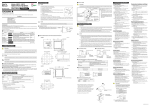
■ UT420 Standard Type (Model UT420-0䊐)
䊏 Receiving 4-20 mA DC Current
Signals with the Controller
13 -
5
10
10
* Wiring can only be carried out for
controllers with remote input.
Remote input
SDA(-)
27
Heating-side control output
Relay contact output Note: Select this option from the OT parameter.
*Time proportional PID relay contact
1
NC
1
output is configured at factory
before shipment.
2
NO
2
3
COM
3
4
Power supply
24
26
Contact rating: 250 V AC, 3 A
30 V DC, 3 A (resistance load)
Power supply
for controllers with communication
functions.
Maximum baud rate: 9600 bps
23 SDB(+)
*Time proportional PID
relay contact output is
configured at factory
before shipment.
48
PV input * Not configured at factory before shipment
See Initial Settings User’s Manual ,
for more information.
RS-485 communication * Wiring can only be carried out
18
20
COM 20
Common
Common
NOTE: External Contact Input
If the power is turned on when the external contact input is OFF, the mode (SPN, R/L, or A/M) existing
before the power is turned off will be continued. (except for RUN/STOP)
■ UT450 Heating/Cooling Type (Model UT450-2䊐)
19
COM
Correspondence between parameter OT and control output types
OT=0 (factory-set default)
DI5
DI6
DI6 37
No function
No function
Transistor contact
DI1
DI2
DI5 38
No function
No function
No function
DI6 OFF OFF OFF OFF OFF OFF OFF ON
* If all of the contact inputs are set to OFF, the controller
uses the immediately preceding target setpoint.
No function
30
When DIS=3
STOP when DI3=ON AUTO when DI3=ON STOP when DI3=ON DI3 40
RUN when DI3=OFF MAN when DI3=OFF RUN when DI3=OFF
AUTO when DI4=ON DI4 39
No function
No function
MAN when DI4=OFF
1.SP2.SP 3.SP4.SP 5.SP6.SP7.SP 8.SP
No function
Common
When DIS=2
When switching target SP 1 to 8:
No function
Relay contact rating: 240 V AC, 1 A
30 V DC, 1 A (resistance load)
Transistor contact rating: 24 V DC, 50 mA
28
* If 15 V DC loop power supply is used,
retransmission output cannot be used.
* DIS is a setup parameter.
Changing DIS setpoint allows you to change the function of external contact input.
Alarm output
19
* PV retransmission is configured at factory
before shipment.
15 -
Transistor contact
+5V
Note: Connecting a 250 Ω resistor to the terminals is
optional.
Model: X010-250-2 (resistor with M3.5 crimp-on terminal
lugs)
12 +
Allowable range: 100 to 240 V AC (10%)
(free voltage)
50/60 Hz shared
+5V
DI2 18
Common
8
N
Contact
UT
DI1 19
When DIS=4
set the PV input type to 1-5 V DC (setpoint “41”).
12 +
Remote input
47
CAUTION
Transistor
Transistor
* Alarm-4 output is
optional function
DI3
DI4
DI5
DI6
No function
1.SP2.SP 3.SP4.SP 5.SP6.SP7.SP 8.SP
ON OFF ON OFF ON OFF ON OFF
OFF ON ON OFF OFF ON ON OFF
OFF OFF OFF ON ON ON ON OFF
OFF OFF OFF OFF OFF OFF OFF ON
49
Relay
When switching target SP 1 to 8:
No function
When DIS=3
* When receiving 4-20 mA DC current signals,
RTD input
10
When DIS=1 (Factory-shipped setting)
AL3 4
Alarm-3 output
L
(Reverse)
14.5-18.0VDC
(21 mA DC max.)
When DIS=0
AL2 5
Alarm-2 output
48
Power supply
* If 15 V DC loop power supply is used,
retransmission output cannot be used.
Correspondence between parameter DIS and external contact input functions
AL1 6
H
(Direct)
Power supply
* DIS is a setup parameter.
Changing DIS setpoint allows you to change the function of external contact input.
When DIS=2
TC input
Default: 1-5 V DC
Contact rating: 250 V AC, 3 A Resistance: 100 to 2.5 k
30 V DC, 3 A (resistance load)
Load resistance: 600 Ω or less
15 V DC loop power supply
4-20 mA DC,
voltage pulse
(12 V)
SDA(-)
Feedback input
4-20 mA DC
15 -
UT
- 44
25 RDB(+)
Relay contact output
* PV retransmission is configured at factory
before shipment.
15 -
14 +
Alarm output
24
14 +
10
Allowable range: 100 to 240 V AC (10%)
(free voltage)
50/60 Hz shared
+ 43
䊏 Receiving 4-20 mA DC Current
Signals with the Controller
PV input * Not configured at factory before shipment
See Initial Settings User’s Manual ,
for more information.
for controllers with communication
functions.
Maximum baud rate: 9600 bps
* Wiring can only be carried out for
controllers with remote input.
23 SDB(+)
Position proportional control output
13 -
Retransmission output
RS-485 communication * Wiring can only be carried out
13 -
Note: Connecting a 250 Ω resistor to the terminals is
optional.
Model: X010-250-2 (resistor with M3.5 crimp-on terminal
lugs)
15
6
21.6-28.0VDC
(30 mA DC max.)
250 Ω 4-20mA
12 +
Before carrying out wiring, turn off the power
to the controller and check that cables to be
connected are not alive with a tester or the like
because there is a possibility of electric shock.
8
12 +
12 b
mV/V input
CAUTION
L
set the PV input type to 1-5 V DC (setpoint “41”).
12 +
SG
*Wiring can only be carried out for controllers with 24 V
DC loop power supply.
24 V DC loop
power supply
* When receiving 4-20 mA DC current signals,
RTD input
Default: 1-5 V DC
Contact rating: 250 V AC, 3 A
30 V DC, 3 A (resistance load)
Power supply
TC input
Specify in a range of
1-5 V DC, 0-2 V DC,
or 0-10 V DC.
22 -
Note: Select this option from
the OT parameter.
*Time proportional PID relay contact
output is configured at factory
before shipment.
Power supply
䊏 Receiving 4-20 mA DC Current
Signals with the Controller
PV input * Not configured at factory before shipment
See Initial Settings User’s Manual ,
for more information.
11 A
RDA(-)
27
Control output
* Wiring can only be carried out for
controllers with remote input.
Remote input
21 +
25 RDB(+)
26
NC
for controllers with communication
functions.
Maximum baud rate: 9600 bps
■ UT450 Position Proportional Type (Model UT450-1䊐 or UT450-4䊐)
External
resistor 250
(Note)
29
28
PV input
1 to 5 V DC signal
13
30
Two-wire transmitter
43
Loop power
supply
21.6 to
28.0 V DC
4-20mADC
44
Correspondence between parameter OT and control output types
OT=0 (factory-set default)
OT=1
OT=2
OT=3
Time proportional control
Relay output (terminals 1 , 2 and 3 )
Time proportional control
Voltage pulse output (terminals 16 and 17 )
Current output
(terminals 16 and 17 )
On-off control
Relay output (terminals 1 , 2 and 3 )
Note: Connecting a 250 resistor to the terminals is optional.
Model: X010-250-2 (resistor with M3.5 crimp-on terminal lugs)
IM 05D01C12-01E (2)