1
Technical
Information
UT450/UT420
Digital Indicating Controller
TI 05D01C12-01E
UT450
UT420
UT450/UT420
Combines the simplicity of the UT350/UT320
with the most popular features of the UT550/UT520.
TI 05D01C12-01E
© Copyright Mar. 2001
1st Edition: Mar. 2001
Blank Page
<Toc> <Ind> <Rev>
i
<Introduction>
Introduction
This Book !
(TI 05D01C12-01E)
This technical information descibes the function of the
UT450 and UT420 Digital Indicating Controllers.
Note : For operating procedures, be careful to refer to the
corresponding User’s Manual (those are descibed
below.)
The following User’s Manuals are attached when the UT450/UT420
controller is shipped from factory.
· A2-size User’s Manual (4 copies) (IM 05D01C12-01E to 04E)
A2-size User’s Manual
(4 copies)
· A4-size User’s Manual of UT450/UT420 can be purchased separately
if necessary. (Document No. : IM 05D01C12-41E)
The contents are same as those of A2-size User’s Manuals.
· The following User’s Manuals also can be purchased if necessary.
Type
A4-size
UT450/UT420
A2-size *
+
CD-ROM*
Title
Doc No.
GREEN Series Communication
Functions
IM 05G01B02-01E
GREEN Series Communication
Reference
IM 05G01B02-02E
GREEN Series User’s Manual
- Detailed Functions -
IM 05J01B02-01E
Digital Indicating Controller
User’s Manual (4 copies)
IM 05D01C12-00E
GREEN Series User’s Manual
- Reference - (CD-ROM Edition)
IM 05D01A02-01E
* These are same User’s Manuals those are attached to the controller.
disc
YOKOGAWA
User’s Manual -Reference-
· CD-ROM type User’s Manual (IM 05D01A02-01E)
Including the manuals of “Reference” and “Communication.”
TI 05D01C12-01E
1st Edition : Mar. 30, 2001-00
Blank Page
Toc-1
<Int> <Ind> <Rev>
UT450/UT420
Digital Indicating Controller
TI 05D01C12-01E 1st Edition
CONTENTS
1.
2.
3.
OVERVIEW .............................................................................................. 1-1
1.1
External Dimensions and Panel Cutout Dimensions .................................... 1-3
1.2
Function Block Diagram for Standard Type(UT450/420) .............................. 1-4
1.3
Function Block Diagram for Heating/Cooling Type (UT450) ......................... 1-5
1.4
Function Block Diagram for Position Proportional Type (UT450) ................ 1-6
INSTALLATION AND WIRING ................................................................. 2-1
2.1
Installation Location ....................................................................................... 2-1
2.2
How to Install ................................................................................................... 2-1
2.3
How to Connect Wires .................................................................................... 2-3
2.3.1
Cable Specifications and Recommended Cables .............................. 2-4
2.3.2
Recommended Terminal Lugs .......................................................... 2-4
2.3.3
Terminal Covers ................................................................................ 2-5
2.3.4
Wiring for 15V DC/24V DC Loop Power Supply ................................ 2-6
2.4
Terminal Arrangement Diagrams ................................................................... 2-7
2.5
Input/Output Circuit Block Diagrams ............................................................ 2-11
OPERATIONS .......................................................................................... 3-1
3.1
Names and Functions of Front Panel Parts ................................................... 3-1
3.2
Key Operation Principles ............................................................................... 3-2
3.3
Operating Display ........................................................................................... 3-3
3.3.1
3.4
4.
SELECT Display ............................................................................... 3-4
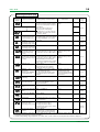
PARAMETERS ................................................................................................. 3-5
3.4.1
Parameter Setting Flow .................................................................... 3-5
3.4.2
Setup Parameter Setting Flow .......................................................... 3-6
3.4.3
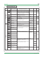
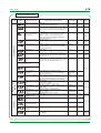
Parameter List .................................................................................. 3-7
MEASURED INPUT ................................................................................. 4-1
4.1
Universal Input ................................................................................................ 4-1
4.2
Measured Input Related Parameters ............................................................. 4-3
4.3
PV Input Unit ................................................................................................... 4-3
4.4
Changing the Measurement Range (Scaling) ................................................ 4-4
4.5
Selection of PV input burnout action ............................................................. 4-5
4.6
Reference Junction Compensation ............................................................... 4-6
4.7
PV Input Bias ................................................................................................... 4-6
TI 05D01C12-01E
1st Edition : Mar. 30, 2001-00
Toc-2
<Int> <Ind> <Rev>
5.
4.8
Filter ................................................................................................................. 4-7
4.9
Ratio bias computing ...................................................................................... 4-7
CONTROL OUTPUT ................................................................................ 5-1
5.1
Universal Output ............................................................................................. 5-1
5.2
Time Proportional PID Output
(Relay Output / Voltage Pulse Output) ........................................................... 5-2
5.3
5.2.1
Cycle Time ........................................................................................ 5-2
5.2.2
Time Proportional PID Control Application Examples ........................ 5-3
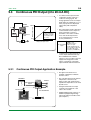
Continuous PID Output (4 to 20 mA DC) ........................................................ 5-4
5.3.1
5.4
5.5
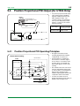
Position Proportional PID Output (for UT450 Only) ...................................... 5-5
5.4.1
Position Proportional PID Operating Principles ................................. 5-5
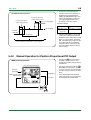
5.4.2
Manual Operation for Position Proportional PID Output .................... 5-6
ON/OFF Control .............................................................................................. 5-7
5.5.1
ON/OFF Control and Hysteresis ....................................................... 5-7
5.5.2
ON/OFF Control Application Example ............................................... 5-7
5.6
Heating/Cooling Control ................................................................................. 5-8
5.7
Direct Actin / Reverse Action Selection ....................................................... 5-10
5.7.1
5.8
5.9
6.
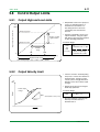
Control Output Limits ....................................................................................5-11
5.8.1
Output High and Low Limits ............................................................. 5-11
5.8.2
Output Velocity Limit ........................................................................ 5-11
Preset Output Value ...................................................................................... 5-12
How to Start / Cancel Auto-Tuning ................................................................. 6-1
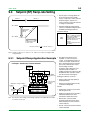
“SUPER” AND “SUPER2” FUNCTIONS ................................................. 7-1
7.1
7.2
8.
Direct / Reverse Action Selection, Using External Contact Input ...... 5-10
AUTO-TUNING ........................................................................................ 6-1
6.1
7.
Continuous PID Output Application Example .................................... 5-4
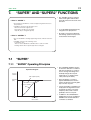
“SUPER” .......................................................................................................... 7-1
7.1.1
“SUPER” Operating Principles .......................................................... 7-1
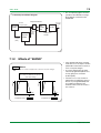
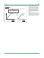
7.1.2
Effects of “SUPER” ........................................................................... 7-2
“SUPER2” ........................................................................................................ 7-4
7.2.1
“SUPER2” Operating Principles ........................................................ 7-4
7.2.2
Effects of “SUPER2” ......................................................................... 7-5
7.2.3
How to Apply “SUPER2” ................................................................... 7-7
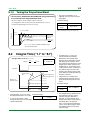
CONTROL PARAMETERS (PID CONSTANTS)....................................... 8-1
8.1
8.2
Proportional Band (P) ..................................................................................... 8-1
8.1.1
Differences between ON / OFF Action and Proportional Action ......... 8-1
8.1.2
Proportional Band (“1. P” to “8. P”) Details ........................................ 8-1
8.1.3
Tuning the Proportional Band............................................................ 8-2
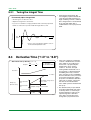
Integral Time (“1.I” to “8.I”) ............................................................................ 8-2
8.2.1
Tuning the Integral Time ................................................................... 8-3
TI 05D01C12-01E
1st Edition : Mar. 30, 2001-00
Toc-3
<Int> <Ind> <Rev>
8.3
Derivative Time (“1.D” to “8.D”) ..................................................................... 8-3
8.3.1
9.
8.4
Manual PID Tuning Procedure ........................................................................ 8-4
8.5
Anti-Reset Wind-up (AR) ................................................................................ 8-5
8.6
Zone PID .......................................................................................................... 8-6
8.6.1
Reference Points .............................................................................. 8-6
8.6.2
Reference Deviation (RDV) .............................................................. 8-6
SETPOINT ............................................................................................... 9-1
9.1
Setpoint Setting Type Overview ..................................................................... 9-1
9.2
Allowable Range for Setpoints (n. SP) Variation ........................................... 9-1
9.3
Setpoint (SP) Ramp-rate Setting .................................................................... 9-2
9.3.1
10.
Tuning the Derivative Time ............................................................... 8-4
Setpoint Ramp Application Example ................................................. 9-2
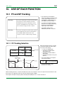
USE OF EACH FUNCTION .................................................................... 10-1
10.1
10.2
10.3
10.4
10.5
10.6
PV and SP Tracking ...................................................................................... 10-1
10.1.1
PV Tracking Selection ..................................................................... 10-1
10.1.2
SP Tracking Selection ..................................................................... 10-2
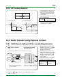
Mode Transfer Using External Contact ........................................................ 10-2
10.2.1
REM (Remote Setting) /LOCAL (Local Setting) Selection ............... 10-2
10.2.2
First/Second/Third/Fourth Setpoint Selection .................................. 10-5
10.2.3
AUTO (Automatic)/MAN Selection .................................................. 10-5
10.2.4
RUN (Oparating)/STOP (Oparation Stopping) Selection ................. 10-6
Alarms ........................................................................................................... 10-9
10.3.1
Alarm Type and Alarm Action .......................................................... 10-9
10.3.2
Timer Function ............................................................................... 10-11
10.3.3
Sensor Ground Alarm ................................................................... 10-12
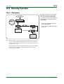
Security Function ........................................................................................ 10-14
10.4.1
Password ..................................................................................... 10-14
10.4.2
Key Lock ....................................................................................... 10-15
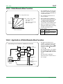
Remote Setpoint Input ................................................................................ 10-16
10.5.1
Remote Setpoint Input Scaling and Filtering ................................. 10-16
10.5.2
Ratio/Remote Bias Function ......................................................... 10-17
10.5.3
Application of Ratio/Remote Bias Function ................................... 10-17
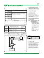
Retransmission Output .............................................................................. 10-18
10.6.1
Retransmission Output Application ............................................... 10-18
10.7
Loop Power Supply .................................................................................... 10-19
10.8
Communications ......................................................................................... 10-20
10.8.1
Communications Overview ........................................................... 10-20
10.8.2
MODBUS Communication ............................................................ 10-22
10.8.3
Personal Computer Link Communication ...................................... 10-27
10.8.4
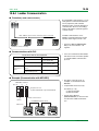
Ladder Communication ................................................................. 10-36
10.8.5
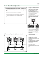
Coordinated Operation ................................................................. 10-37
TI 05D01C12-01E
1st Edition : Mar. 30, 2001-00
Toc-4
<Int> <Ind> <Rev>
10.9
11.
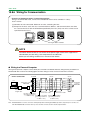
Wiring for Communication ............................................................. 10-38
10.8.7
D register (of UT450/420) ............................................................. 10-41
10.8.8
I Relays (of UT450/420) ................................................................ 10-43
LL100 (PC-Based Parameters Setting Tool) .............................................. 10-45
10.9.1
Functions ...................................................................................... 10-45
10.9.2
Connection Between the Controller and a Personal Computer ...... 10-46
SELF-DIAGNOSTICS AND POWER FAILURE COUNTERMEASURES 11-1
11.1
12.
10.8.6
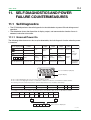
Self-Diagnostics ............................................................................................. 11-1
11.1.1
Errors at Power On .......................................................................... 11-1
11.1.2
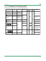
Possible Errors During Operation..................................................... 11-2
11.2
Behavior on the Event of Power Failure or after Power Recovery .............. 11-3
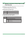
11.3
Preset Output Value (Output Value in Event of Controller Problem) ........... 11-4
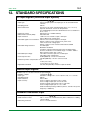
STANDARD SPECIFICATIONS ............................................................. 12-1
TI 05D01C12-01E
1st Edition : Mar. 30, 2001-00
1-1
<Toc> <Ind>
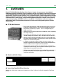
1.
OVERVIEW
Model UT450/420 Digital Indicating Controller is a simple, micro-processor based digital
indicating controller with basic control capability and the user-friendly large numerical display.
The UT450/420 features as standard many functions which are necessary for various control
applications, and all of these functions such as control function, control computation function,
signal computation function, etc. can be configured by using the keys on the front panel. The
instrument has an Auto-tuning, an Overshoot-suppressing function “SUPER” and a hunting
suppressing function “SUPER2” built in as standard. It is suitable for a diverse range of
applications, with UT450 position-proportional control and heating/cooling control models
also available.
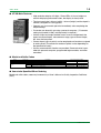
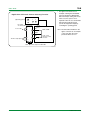
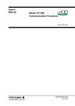
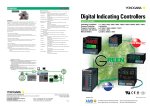
● UT450 Main Features
• Extra-large digital display allows the indicated values to be read
even from a long distance. LEDs of 20 mm height are used for
the process variable (PV) display. This is a 5-digit display for
higher resolution.
• Operator can start control operation immediately after completing
the simple settings.
• Parameters can be easily set using a personal computer. (“Parameter setting tool (model LL100)” sold separately is required.)
• Universal input and output enables users to set or change freely
the type of measured inputs, measurement range, type of control
output, etc. from the front panel.
F1-01.EPS
• In addition to general purpose models (universal output), the
position-proportional model (relay output) or the heating/cooling
control model (universal output) can be specified.
• Contact inputs (up to 7 points) can be employed and functions
assigned to each contact (The maximum number of points varies
depending on the specification code.)
• Various communication function are provided. Communication is
possible with personal computer, programable logic controller,
and other controllers.
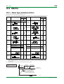
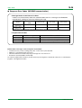
● Model and Suffix Codes
Model
Suffix Code
UT450
Type
Options
-0
-1
-2
-3
-4
0
1
2
3
4
Description
Digital indicating controller (1/4 DIN)
Standard type
Position-proportional type
Heating/cooling type
Standard type with 24V DC loop power supply
Position-proportional type with 24V DC loop power supply
None
Communication functions, remote input, 5 additional DIs, 1 additional Alarm
Communication functions, remote input, 1 additional DI
4 additional DIs, 1 additional Alarm
Remote input, 1 additional DI
Contact input/output available
Contact input
Contact output
DI1, DI2
DI1 to DI6, R/L
DI1, DI2, R/L
DI1 to DI6
DI1, DI2, R/L
AL1, AL2, AL3
AL1 to AL4
AL1, AL2, AL3
AL1 to AL4
AL1, AL2, AL3
T1-01.EPS
● Items to be Specified When Ordering
Model and suffix codes, necessary/unnecessary of User’s Manual or Quality Inspection Certificate
(QIC).
TI 05D01C12-01E
1st Edition : Mar. 30, 2001-00
1-2
<Toc> <Ind>
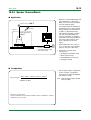
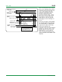
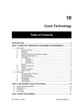
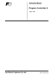
● UT450 Main Features
• High resolution display of 5 digits. Since LEDs of 12 mm height are
used for displaying measured values, the display is clearly read.
• The front panel size is 48 mm (width) × 96 mm (height) and the depth is
100 mm, designed for saving space.
• Operator can start control operation immediately after completing the
simple settings.
• Parameter can be easily set using a personal computer. (“Parameter
setting tool (model LL100)” sold separately is required.)
• Universal input and output enables users to set or change freely the
type of measured inputs, measurement range, type of control output,
etc. from the front panel.
F1-02.EPS
• Contact inputs (up to 4 points) can be employed and functions assigned
to each contact (The maximum number of points varies depending on
the specification code.)
• Various communication function are provided. Communication is possible with personal computer, programable logic controller, and other
controllers.
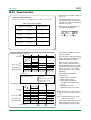
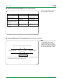
● Model and Suffix Codes
Model
UT420
Type
Options
Suffix Code
-0
0
7
8
Description
Digital indicating controller (1/8 DIN)
Standard type
None
Communication functions, remote input, 2 additional DIs
Remote input, 2 additional DIs
Contact input/output available
Contact input
DI1, DI2
DI1, DI2,DI3, R/L
DI1, DI2,DI3, R/L
Contact output
AL1, AL2, AL3
AL1, AL2, AL3
AL1, AL2, AL3
T1-02.EPS
● Items to be Specified When Ordering
Model and suffix codes, necessary/unnecessary of User’s Manual or Quality Inspection Certificate
(QIC).
TI 05D01C12-01E
1st Edition : Mar. 30, 2001-00
1-3
<Toc> <Ind>
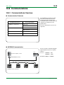
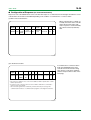
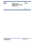
1.1
External Dimensions and Panel Cutout Dimensions
● UT450
Unit: mm
11
96
F1-03.EPS
Large bracket
100
2
3
96
AL1
91.8
REM
MAN
4
112
PV
A/M
SET/ENT
Small bracket
1 to 10 mm (Panel thickness)
General installation
Side-by-side close installation
[(N-1)96+92]
+0.8
0
92
+0.8
0
117 min.
(53)
92
145 min.
"N" stands for the number of controllers to be
installed.
However, the measured value applies if N 5.
+0.8
0
92
+0.8
0
(25)
F1-03.EPS
● UT420
Unit: mm
11
48
100
Small bracket
YOKOGAWA
PV
AL1
2
3
112
96
91.8
REM MAN
SET/ENT
A/M
Small bracket
1 to 10 mm (Panel thickness)
General installation
Side-by-side close installation
70 min.
+0.6
0
92
+0.8
0
[(N-1)48+45]
(53)
92
145 min.
+ 0.8
0
45 + 00.6
(25)
"N" stands for the number of controllers to be
installed.
However, the measured value applies if N 5.
F1-04.EPS
TI 05D01C12-01E
1st Edition : Mar. 30, 2001-00
1-4
<Toc> <Ind>
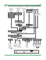
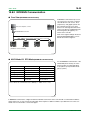
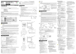
1.2
Function Block Diagram for Standard Type(UT450/420)
PV input
terminals 11, 12 and 13
Remote input
terminals 21 and 22
Communication
terminals 23 to 27
PV INPUT
RSP
INPUT
RS485
Input selection
Input selection
Unit selection
Input range conversion
Contact input
DI3
DI4
DI6
DI1
Input bias
Input filter
Remote setting filter
Aux.Input
Communication
RMS=RSP
RMS=COM
DI2
R/L
*For availabilities on
DI3 to 6 & R/L, refer
to model and suffix codes
in Page 1-1 and 1-2.
Target setpoint selection
Input range conversion
DI5
SPN
Ratio/bias calculation
REMOTE
R/L
Target setpoints 1 to 8
LOCAL
REMOTE (ON)/LOCAL (OFF) switching
Target setpoint
ramp-rate function
Manual operation
Control computation
MAN
A/M
Preset output
24V loop
power supply
AUTO
AUTO (ON)/MAN (OFF) switching
Output limiter
STOP
RUN
S/R
STOP (ON)/RUN (OFF) switching
15 V loop
power supply
OT
Retransmission
output
Control
output
Alarm function
RET
LPS
OUTPUT1
OUTPUT1
RET/LPS
Terminals
43 and 44
Current or pulse
terminals 16 and 17
Relay
terminals
1 , 2 and 3
Current
terminals
14 and 15
AL1
AL2
AL3
AL4
Alarm 1 Alarm 2 Alarm 3 Alarm 4
*LPS 24V is available
on UT450-3 only.
*Alarm 4 output is available
on UT450- 1/- 3 only.
Terminal
Parameter
Function
Analog signal
Contact signal
Front panel key
Legend
F1-05.EPS
TI 05D01C12-01E
1st Edition : Mar. 30, 2001-00
1-5
<Toc> <Ind>
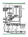
1.3
Function Block Diagram for Heating/Cooling Type (UT450)
PV input
terminals 11, 12 and 13
Remote input
terminals 21 and 22
Communication
terminals 23 to 27
PV INPUT
RSP
INPUT
RS485
Input selection
Input selection
Unit selection
Input range conversion
Contact input
DI3
DI4
DI6
DI1
Input bias
Input filter
Remote setting filter
Aux.Input
Communication
RMS=RSP
RMS=COM
DI2
R/L
*For availabilities on
DI3 to 6 & R/L, refer
to model and suffix
codes in Page 1-1.
Target setpoint selection
Input range conversion
DI5
SPN
Target setpoints 1 to 8
Ratio/bias calculation
REMOTE
R/L
LOCAL
REMOTE (ON)/LOCAL (OFF) switching
Target setpoint
ramp-rate function
Manual operation
Control computation
MAN
A/M
AUTO
AUTO (ON)/MAN (OFF) switching
Heating/cooling
computation
Heating-side
output limiter
Cooling-side
output limiter
Heating-side
preset output
Cooling-side
preset output
OT
OT
Heating-side
output
OUTPUT1
OUTPUT1
S/R
15 V loop
power supply
Cooling-side
output
OUTPUT2
OUTPUT2
STOP (ON)/RUN (OFF) switching
Retransmission
output
Alarm function
RET
OUTPUT3
AL1
AL2
AL3
AL4
Alarm 1 Alarm 2 Alarm 3 Alarm 4
Current or pulse
terminals 16 and 17
Relay
terminals
1 , 2 and 3
Current or pulse
terminals
46 and 47
Relay
terminals
48 , 49 and 50
Current
terminals
14 and 15
*Alarm 4 output is available
on UT450-21/-23 only.
Terminal
Parameter
Function
Analog signal
Contact signal
Front panel key
Legend
F1-06.EPS
TI 05D01C12-01E
1st Edition : Mar. 30, 2001-00
1-6
<Toc> <Ind>
1.4
Function Block Diagram for Position Proportional Type (UT450)
PV input
terminals 11 , 12 and 13
Remote input
terminals 21 and 22
Communication
terminals 23 to 27
PV INPUT
RSP
INPUT
RS485
Input selection
Input selection
Unit selection
Input range conversion
Contact input
DI3
DI4
DI6
DI1
DI2
R/L
*For availabilities on
DI3 to 6 & R/L, refer
to model and suffix
codes in Page 1-1.
Target setpoint selection
Input range conversion
DI5
Input bias
Input filter
Remote setting filter
Aux.Input
Communication
RMS=RSP
RMS=COM
SPN
Ratio/bias calculation
REMOTE
R/L
Target setpoints 1 to 8
LOCAL
REMOTE (ON)/LOCAL (OFF) switching
Target setpoint
ramp-rate function
In MAN operation, relay
is ON when
or
key
is hold down.
Manual operation
Control computation
Output limiter
MAN
AUTO
A/M
AUTO (ON)/MAN (OFF) switching
Preset output
STOP
RUN
S/R
STOP (ON)/RUN (OFF) switching
24 V loop
power supply
Signal comparison
(
L relay
key)
15 V loop
power supply
Retransmission
output
Alarm function
H relay
key)
(
RET
FEEDBACK
terminals
45 , 46 and 47
OUTPUT
terminals
48 , 49 and 50
LPS
RET/LPS
Direct/reverse signal
M
AL2
AL3
AL4
Alarm 1 Alarm 2 Alarm 3 Alarm 4
Terminals
Relay output 43 and 44
Feed-back
input
AL1
Motor-driven valve
Current
terminals 14 and 15
*Alarm 4 output is available
on UT450-41 & 43 only.
*LPS 24V is available
on UT450-4 only.
Valve position
sliding resistor
Terminal
Parameter
Function
Analog signal
Contact signal
Front panel key
Legend
F1-07.EPS
TI 05D01C12-01E
1st Edition : Mar. 30, 2001-00
2-1
<Toc> <Ind>
2.
INSTALLATION AND WIRING
2.1
Installation Location
To install the controller, select a location where:
1. no one may accidentally touch the terminals,
150 mm
2. mechanical vibrations are minimal,
150 mm
3. corrosive gas is minimal,
150 mm
150 mm
4. temperature can be maintained at about 23°C and the fluctuation is minimal,
5 no direct radiant heat is present,
F2-01.EPS
6. no magnetic disturbances are caused,
7. no wind blows against the terminal board (reference junction compensation element),
8. no water is splashed,
9. no flammable materials are around,
Never place the controller directly on flammable items or equipment.
If the controller has to be installed close to flammable items or equipment, be sure to provide shielding
panels all around the controller, at least 150 mm away from every side; the panels should be made of
either 1.43 mm-thick metal-plated steel plates or 1.6 mm-thick uncoated steel plates.
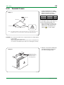
2.2
How to Install
CAUTION:
Turn off the power to the controller before installing it on the panel because there is a possibility
of electric shock.
After opening the mounting hole on the panel, follow the procedures below to install the controller:
1. Insert the controller into the opening from the front of the panel so that the terminal board on the
rear is at the far side.
2. Set the brackets in place on the top and bottom of the controller as shown in the figure below, then
tighten the screws of the brackets. Take care not to overtighten them.
Large bracket
Panel
(top mounting hardware)
Terminal board
Direction to insert the
controller
Insert the controller
into the opening at
the front of the panel.
Insert a screwdriver into the
brackets to tighten the screws.
Small bracket
(bottom mounting hardware)
F2-02.EPS
TI 05D01C12-01E
1st Edition : Mar. 30, 2001-00
2-2
<Toc> <Ind>
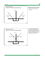
● Installation Position
Install the controller at an angle within
30° from horizontal with the front panel
facing upward. Do not install it facing
downward. The position of right and left
sides should be horizontal.
Front panel
of controller
Must not
exceed 30
30
Rear of
controller
F2-03.EPS
TI 05D01C12-01E
1st Edition : Mar. 30, 2001-00
2-3
<Toc> <Ind>
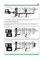
2.3
How to Connect Wires
CAUTION:
1)
Before carrying out wiring, turn off the power to the controller and check that the cables to
be connected are not alive with a tester or the like because there is a possibility of electric
shock.
2)
Wiring must be carried out by personnel who have basic electrical knowledge and practical
experience.
For DC Relay Wiring
UT450/UT420
External DC power supply
For AC Relay Wiring
UT450/UT420
External AC power supply
O.C Relay
R
R
UT s contact
Relay
(Use one with a relay coil
rating less than the UT s
contact rating.)
Diode
(Mount it directly
to the relay coil
terminal (socket).)
UT s contact
Relay
(Use one with a relay coil
rating less than the UT s
contact rating.)
CR filter
(Mount it directly
to the relay coil
terminal (socket).)
F2-04.EPS
NOTE:
1)
Provide power from a single-phase instrument power supply. If there is a lot of noise in the
power line, insert an insulating transformer into the primary side of the line and use a line
filter (recommended part: ZAC2205-00U from TDK) on the secondary side.
As a countermeasures against noise, do not place the primary and secondary power
cables close to each other.
2)
For thermocouple input, use shielded compensating lead wires for wiring. For RTD input,
use shielded wires that have low conductor resistance and cause no significant differences
in resistance between the three wires.
The cables to be used for wiring, terminal specifications, and recommended parts are as
shown below.
3)
Control output relays may be replaced. However, because they have a life of 100,000
times that of the resistance load, use auxiliary relays to turn on/off a load.
4)
The use of inductance (L) loads such as auxiliary relays, motors and solenoid valves
causes malfunction or relay failure; always insert a CR filter for use with alternating current
or a diode for use with direct current, as a spark-removal surge suppression circuit, into the
line in parallel with the load.
TI 05D01C12-01E
1st Edition : Mar. 30, 2001-00
2-4
<Toc> <Ind>
2.3.1
Cable Specifications and Recommended Cables
• In the case of thermocouple input,
use the proper compensating
leadwire types.
Purpose
Name and Manufacturer
Power supply, grounding,
relay contact outputs
600 V PVC insulated wires, JIS C 3307,
0.9 to 2.0 mm2
Thermocouple
Shielded compensating lead wires, JIS C 1610,
X- (See Yokogawa Electric's GS 6B1U1-E.)
RTD
Shielded wires (three conductors),
UL2482 (Hitachi Cable)
Other signals
Shielded wires
• For RTD input, use wiring having low
conductor resistance, and so significant differences in resistance among
the three conductors.
• For power supply wiring, use a cable
or wiring with the characteristics of
600V vinyl insulated wire (JIS C3307)
or equivalent.
F2-05.EPS
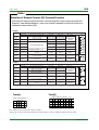
2.3.2
Recommended Terminal Lugs
• When connecting the wiring to the
terminals, we recommend use of
solderless crimp terminal lugs with
insulated sleeves.
Applicable wire size
0.3 to 1.65 mm2
Tightening torque
0.8 N-m or less
3.7mm
or
7 mm or less
7 mm or less
3.7mm
F2-06.EPS
TI 05D01C12-01E
1st Edition : Mar. 30, 2001-00
2-5
<Toc> <Ind>
2.3.3
Terminal Covers
• An optional terminal cover, used to
keep the terminals from accidentally
being touched and to prevent
electrics shocks, is also available.
< Step-1 >
Target Model
For UT450
For UT420
Fold over.
Part Number Sales Unit
T9115YD
1
T9115YE
1
Grooved
See the figure <step-1> and <step-2> on
the left to attach the terminal cover.
1 Before attaching the terminal cover,
fold it once or twice so that the side
which has the “Handle With Care”
), is on the outside.
symbol (
Fold over.
Grooved
Alert symbol
on the back
Note: Do not fold the terminal cover the wrong way, doing so not only reduces the cover’s
strength but may also cause the hinge to crack, thereby disabling attachment.
F2-07.EPS
CAUTION: Do not touch the terminals on the rear panel when power is being supplied
to the controller.
Doing so may result in electric shock.
Before attaching the terminal cover, turn off the source circuit breaker and
use a tester to check that the power cable is not conducting any electricity.
2 With the cover properly folded, fit the
top and bottom holes to the protrusion of the mounting brackets.
< Step-2 >
Fit the hole of the
terminal cover to the
protrusion on the
mounting bracket.
F2-07-01.EPS
TI 05D01C12-01E
1st Edition : Mar. 30, 2001-00
2-6
<Toc> <Ind>
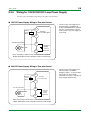
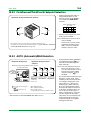
2.3.4
Wiring for 15V DC/24V DC Loop Power Supply
(See 10.7 Loop Power Supply on Page 10-19 for the outline of these function.)
● 15V DC Power Supply Wiring to Two-wire Sensor
• 15V DC Loop Power Supply for twowire transmitter is available in all
models of UT450/UT420 as standard
function. If retransmission output is
used, 15V DC loop power supply can
not be used.
12
External
resistor 100
(Note)
PV input
0.4 to 2.0 V DC signal
13
Two-wire transmitter
14
4-20mADC
15
Loop power
supply
14.5 to
18.0 V DC
Note: Connecting a 100 resistor to the terminals is optional.
Model: X010-100-2 (resistor with M3.5 crimp-on terminal lugs)
F2-07-02.EPS
● 24V DC Power Supply Wiring to Two-wire Sensor
• 24V DC Loop Power Supply for twowire transmitter is available in
UT450-3 and 4. In these models,
this function can be used with
retransmission output or 15V DC loop
power supply simultaneously.
12
External
resistor 250
(Note)
PV input
1 to 5 V DC signal
13
Two-wire transmitter
43
Loop power
supply
21.6 to
28.0 V DC
4-20mADC
44
Note: Connecting a 250 resistor to the terminals is optional.
Model: X010-250-2 (resistor with M3.5 crimp-on terminal lugs)
F2-07-03.EPS
TI 05D01C12-01E
1st Edition : Mar. 30, 2001-00
2
3
NO
COM
10
9
8
Relay
SG
27
COM 35
COM 7
Common
Common
AL3 4
Alarm-3 output
AL4 34
AL2 5
Alarm-2 output
Alarm-4 output
AL1 6
Alarm output
Alarm-1 output
UT
Relay contact rating: 240 V AC, 1 A
30 V DC, 1 A (resistance load)
Transistor contact rating: 24 V DC, 50 mA
Transistor
TI 05D01C12-01E
49
50
9
10
40
39
38
37
36
35
34
33
32
31
30
29
28
27
26
25
24
23
22
21
20
19
18
17
16
15
14
13
12
11
22 -
21 +
17 -
16 +
4-20 mA DC,
voltage pulse
(12 V)
Control output
Current/voltage
pulse output
Default: 1-5 V DC
Specify in a range of
1-5 V DC, 0-2 V DC,
or 0-10 V DC.
AUTO when DI1=ON
MAN when DI1=OFF
No function
1.SP2.SP 3.SP4.SP 5.SP6.SP7.SP 8.SP
Common
Remote when R/L=ON
Local when R/L=OFF
Remote when R/L=ON
Local when R/L=OFF
Common
Common
OT=1
Time proportional control
Voltage pulse output (terminals 16 and 17 )
OT=0 (factory-set default)
Time proportional control
Relay output (terminals 1 , 2 and 3 )
When DIS=2
When DIS=3
2.SP when DI2=ON 2.SP when DI2=ON
1.SP when DI2=OFF 1.SP when DI2=OFF
AUTO when DI1=ON STOP when DI1=ON
MAN when DI1=OFF RUN when DI1=OFF
When DIS=4
DI2 OFF OFF ON ON
DI1 OFF ON OFF ON
When switching target
SP 1 to 4:
1.SP2.SP3.SP 4.SP
Current output
(terminals 16 and 17 )
OT=2
14.5-18.0VDC
(21 mA DC max.)
No function
Common
No function
No function
Common
No function
COM 20
DI6 37
DI5 38
DI4 39
DI3 40
DI2 18
Contact
UT
DI1 19
OT=3
Common
Common
COM
R/L
COM
DI6
DI5
DI4
DI3
DI2
DI1
Contact rating: 12 V DC, 10 mA or more
COM 30
+5V
+5V
+5V
+5V
+5V
+5V
+5V
30
28
20
37
38
39
40
18
19
Transistor contact
* If 15 V DC loop power supply is used,
retransmission output cannot be used.
Load resistance: 600 Ω or less
* PV retransmission is configured at factory
before shipment.
Installation category (overvoltage category): II (IEC1010-1)
NOTE
250 Ω 4-20mA
Note: Connecting a 250 Ω resistor to the terminals is
optional.
Model: X010-250-2 (resistor with M3.5 crimp-on terminal
lugs)
13 -
12 +
set the PV input type to 1-5 V DC (range code “41”).
* When receiving 4-20 mA DC current signals,
Receiving 4-20 mA DC Current
Signals with the Controller
F2-08.EPS
Note: External Contact Input
If the power is turned on when the external contact input is OFF,
the mode (SPN, R/L, or A/M) existing before the power is turned
off will be continued. (except for RUN/STOP)
Common
Remote when R/L=ON Remote when R/L=ON Remote when R/L=ON
Local when R/L=OFF Local when R/L=OFF
Local when R/L=OFF
R/L 28
Common
No function
No function
RUN when DI3=OFF MAN when DI3=OFF RUN when DI3=OFF
AUTO when DI4=ON
No function
No function
MAN when DI4=OFF
On-off control
Relay output (terminals 1 , 2 and 3 )
* If all of the contact inputs are set to OFF,
the controller uses the immediately
preceding target setpoint.
DI6 OFF OFF OFF OFF OFF OFF OFF ON
DI5 OFF OFF OFF ON ON ON ON OFF
DI3 ON OFF ON OFF ON OFF ON OFF
DI4 OFF ON ON OFF OFF ON ON OFF
No function
No function
No function
No function
No function
14 +
15 -
When switching target SP 1 to 8: STOP when DI3=ON AUTO when DI3=ON STOP when DI3=ON
STOP when DI2=ON
RUN when DI2=OFF
4-20 mA DC
15 V DC loop power supply
15 -
14 +
Retransmission output
13 -
12 +
mV/V input
13 B
12 b
11 A
RTD input
Correspondence between DIS parameters and external contact input functions
When DIS=1 (Factory-set default)
When DIS=0
No function
13 -
12 +
TC input
PV input * Not configured at factory before shipment
See “2. Initial Settings,” for more
information.
Note:Select this option
from the OT
parameter.
* Wiring can only be carried out for
controllers with remote input.
Remote input
* DIS is a setup parameter.
Changing DIS setpoint allows you to change the function of external contact input.
48
8
46
47
7
6
43
44
3
4
45
42
2
5
41
1
Correspondence between parameter OT and control output types
* OT is a setup parameter.
You can change the settings of the parameter OT to change the
control output type.
See “2. Initial Settings,” for more information.
* Alarm-4 output is
optional function
RDA(-)
26
25 RDB(+)
SDA(-)
Before carrying out wiring, turn off the power
to the controller and check that cables to be
connected are not alive with a tester or the like
because there is a possibility of electric shock.
Allowable range: 100 to 240 V AC (10%)
(free voltage)
50/60 Hz shared
N
L
Power supply
Power supply
CAUTION
Note: Select this option from
the OT parameter.
*Time proportional PID relay contact
output is configured at factory
before shipment.
Contact rating: 250 V AC, 3 A
30 V DC, 3 A (resistance load)
1
NC
Relay contact output
Control output
- 44
+ 43
24
23 SDB(+)
for controllers with communication
functions.
Maximum baud rate: 9600 bps
RS-485 communication * Wiring can only be carried out
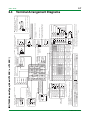
2.4
21.6-28.0VDC
(30 mA DC max.)
* Wiring can only be carried out for controllers with
24 V DC loop power supply.
24 V DC loop
power supply
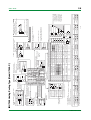
■ UT450 Standard Type (Model UT450-0 or UT450-3)
<Toc> <Ind>
2-7
Terminal Arrangement Diagrams
1st Edition : Mar. 30, 2001-00
50
COM
SDA(-)
10
9
8
Relay
COM 35
Common
COM 7
Common
AL4 34
AL3 4
Alarm-3 output
Alarm-4 output
AL2 5
Alarm-2 output
49
50
9
10
TI 05D01C12-01E
37
40
39
38
25
30
29
28
27
26
20
19
18
17
16
15
14
13
12
11
13 -
12 +
TC input
17 -
16 +
4-20 mA DC,
voltage pulse
(12 V)
Heating-side control output
Note:Select this option
Current/voltage
from the OT
pulse output
parameter.
Default: 1-5 V DC
Specify in a range of
1-5 V DC, 0-2 V DC,
or 0-10 V DC.
1.SP2.SP 3.SP4.SP 5.SP6.SP7.SP 8.SP
OT=6
Heating side: Current output
(terminals 16 and 17 )
Cooling side: Relay output
(terminals 48 , 49 and 50 )
14.5-18.0VDC
(21 mA DC max.)
No function
DI1 OFF ON OFF ON
DI2 18
Contact
UT
DI1 19
Common
No function
No function
Common
No function
No function
Common
Common
Common
OT=7
Heating side: Relay output
(terminals 1 , 2 and 3 )
Cooling side: Voltage pulse output
(terminals 46 and 47 )
OT=8
Heating side: Voltage pulse output
(terminals 16 and 17 )
Cooling side: Voltage pulse output
(terminals 46 and 47 )
OT=9
Heating side: Current output
(terminals 16 and 17 )
Cooling side: Voltage pulse output
(terminals 46 and 47 )
+5V
+5V
OT=10
Heating side: Relay output
(terminals 1 , 2 and 3 )
Cooling side: Current output
(terminals 46 and 47 )
30
28
20
37
38
39
40
18
19
OT=11
Transistor contact
F2-09.EPS
Heating side: Voltage pulse output
(terminals 16 and 17 )
Cooling side: Current output
(terminals 46 and 47 )
COM
R/L
COM
DI6
DI5
DI4
DI3
DI2
DI1
Contact rating: 12 V DC, 10 mA or more
COM 30
R/L 28
COM 20
DI6 37
DI5 38
+5V
+5V
+5V
+5V
+5V
* If 15 V DC loop power supply is used,
retransmission output cannot be used.
Load resistance: 600 Ω or less
* PV retransmission is configured at factory
before shipment.
AUTO when DI4=ON
DI4 39
MAN when DI4=OFF
RUN when DI3=OFF
DI2 OFF OFF ON ON
Remote when R/L=ON Remote when R/L=ON Remote when R/L=ON
Local when R/L=OFF Local when R/L=OFF
Local when R/L=OFF
Common
No function
No function
No function
RUN when DI3=OFF MAN when DI3=OFF
2.SP when DI2=ON 2.SP when DI2=ON
1.SP when DI2=OFF 1.SP when DI2=OFF
When DIS=2
When DIS=3
When DIS=4
switching target
AUTO when DI1=ON STOP when DI1=ON When SP
1 to 4:
MAN when DI1=OFF RUN when DI1=OFF
1.SP2.SP3.SP 4.SP
Correspondence between parameter OT and heating-side/cooling-side output types
Common
Remote when R/L=ON
Local when R/L=OFF
Remote when R/L=ON
Local when R/L=OFF
* If all of the contact inputs are set to OFF,
the controller uses the immediately
preceding target setpoint.
DI6 OFF OFF OFF OFF OFF OFF OFF ON
DI5 OFF OFF OFF ON ON ON ON OFF
DI3 ON OFF ON OFF ON OFF ON OFF
DI4 OFF ON ON OFF OFF ON ON OFF
Common
Common
15 -
14 +
NOTE
250 Ω 4-20mA
Heating side: Current output
(terminals 16 and 17 )
Cooling side: Current output
(terminals 46 and 47 )
OT=12
Note: External Contact Input
If the power is turned
on when the external
contact input is OFF,
the mode (SPN, R/L,
or A/M) existing before
the power is turned off
will be continued.
(except for RUN/STOP)
Note: Connecting a 250 Ω resistor to the terminals is
optional.
Model: X010-250-2 (resistor with M3.5 crimp-on terminal
lugs)
13 -
12 +
set the PV input type to 1-5 V DC (range code “41”).
* When receiving 4-20 mA DC current signals,
Receiving 4-20 mA DC Current
Signals with the Controller
Installation category (overvoltage category): II (IEC1010-1)
When switching target SP 1 to 8: STOP when DI3=ON AUTO when DI3=ON STOP when DI3=ON
DI3 40
No function
No function
No function
No function
No function
STOP when DI2=ON
RUN when DI2=OFF
AUTO when DI1=ON
MAN when DI1=OFF
No function
No function
4-20 mA DC
15 V DC loop power supply
15 -
14 +
Retransmission output
13 -
12 +
mV/V input
13 B
12 b
11 A
RTD input
Correspondence between parameter DIS and external contact input functions
When DIS=1 (Factory-set default)
When DIS=0
The control output types, “relay output” and “voltage pulse output” shown in the table above refer to those of time proportional control.
To change the type to a relay output for on-off control, select “Relay Terminals” and change the setpoint of the proportional band to “0.”
OT=5
Heating side: Voltage pulse output
(terminals 16 and 17 )
Cooling side: Relay output
(terminals 48 , 49 and 50 )
OT=4 (factory-set default)
Heating side: Relay output
(terminals 1 , 2 and 3 )
Cooling side: Relay output
(terminals 48 , 49 and 50 )
35
36
24
23
22
21
22 -
21 +
* Wiring can only be carried out for
controllers with remote input.
Remote input
PV input * Not configured at factory before shipment
See “2. Initial Settings,” for more
information.
* DIS is a setup parameter.
Changing DIS setpoint allows you to change the function of external contact input.
47
48
7
8
Relay contact rating: 240 V AC, 1 A
30 V DC, 1 A (resistance load)
Transistor contact rating: 24 V DC, 50 mA
Transistor
* OT is a setup parameter.
You can change the settings of the parameter OT to change the
control output type.
See “2. Initial Settings,” for more information.
* Alarm-4 output is
optional function
AL1 6
Alarm-1 output
Alarm output
Before carrying out wiring, turn off the power
to the controller and check that cables to be
connected are not alive with a tester or the like
because there is a possibility of electric shock.
Allowable range: 100 to 240 V AC (10%)
(free voltage)
50/60 Hz shared
N
L
Power supply
UT
45
46
5
CAUTION
6
Power supply
32
42
Contact rating: 250 V AC, 3 A
30 V DC, 3 A (resistance load)
31
41
33
SG
RDA(-)
34
27
26
25 RDB(+)
24
23 SDB(+)
43
Contact rating: 250 V AC, 3 A
30 V DC, 3 A (resistance load)
49
NO
*Time proportional PID
relay contact output is
configured at factory
before shipment.
44
- 47
48
NC
Relay contact output
for controllers with communication
functions.
Maximum baud rate: 9600 bps
RS-485 communication * Wiring can only be carried out
Heating-side control output
Relay contact output Note: Select this option from the OT parameter.
*Time proportional PID relay contact
1
NC
1
output is configured at factory
before shipment.
2
NO
2
3
COM
3
4
4-20 mA DC,
voltage pulse
(12 V)
+ 46
Current/voltage pulse output
Note: Select this option from the OT parameter.
Cooling-side control Cooling-side control
output
output
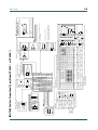
■ UT450 Heating/Cooling Type (Model UT450-2)
<Toc> <Ind>
2-8
1st Edition : Mar. 30, 2001-00
- 44
45
50
COM
10
9
8
Relay
* Alarm-4
output is
optional
specification
Transistor
TI 05D01C12-01E
Relay contact rating: 240 V AC, 1 A
30 V DC, 1 A (resistance load)
Transistor contact rating: 24 V DC, 50 mA
COM 35
COM 7
Common
Common
AL3 4
Alarm-3 output
AL4 34
AL2 5
Alarm-2 output
Alarm-4 output
AL1 6
Alarm output
Alarm-1 output
UT
Before carrying out wiring, turn off the power
to the controller and check that cables to be
connected are not alive with a tester or the like
because there is a possibility of electric shock.
CAUTION
Allowable range: 100 to 240 V AC (10%)
(free voltage)
50/60 Hz shared
N
L
Power supply
Power supply
Contact rating: 250 V AC, 3 A Resistance: 100 to 2.5 k
30 V DC, 3 A (resistance load)
100%
46
49
L
(Reverse)
47
48
0%
Feedback input
H
(Direct)
Relay contact output
Position proportional control output
21.6-28.0VDC
(30 mA DC max.)
+ 43
SDA(-)
50
10
40
39
38
37
36
35
34
33
32
31
30
29
28
27
26
25
24
23
22
21
20
19
18
17
16
15
14
13
12
11
22 -
21 +
Default: 1-5 V DC
Specify in a range of
1-5 V DC, 0-2 V DC,
or 0-10 V DC.
Remote input
13 -
12 +
TC input
1.SP2.SP 3.SP4.SP 5.SP6.SP7.SP 8.SP
When DIS=4
DI2 OFF OFF ON ON
When switching target
SP 1 to 4:
1.SP2.SP3.SP 4.SP
DI1 OFF ON OFF ON
DI2 18
Contact
UT
DI1 19
Common
Common
No function
Common
Remote when R/L=ON
Local when R/L=OFF
Common
No function
Common
No function
No function
COM 20
DI6 37
DI5 38
Common
Common
COM 30
Remote when R/L=ON Remote when R/L=ON
Local when R/L=OFF Local when R/L=OFF R/L 28
Common
No function
No function
RUN when DI3=OFF MAN when DI3=OFF RUN when DI3=OFF
AUTO when DI4=ON
No function
DI4 39
No function
MAN when DI4=OFF
+5V
+5V
+5V
+5V
+5V
+5V
+5V
COM
R/L
COM
DI6
DI5
DI4
DI3
DI2
DI1
30
28
20
37
38
39
40
18
19
F2-10.EPS
Transistor contact
* If 15 V DC loop power supply is used,
retransmission output cannot be used.
Load resistance: 600 Ω or less
* PV retransmission is configured at factory
before shipment.
Contact rating: 12 V DC, 10 mA or more
Note: External Contact Input
If the power is turned on when the external contact input is OFF, the mode (SPN, R/L, or A/M) existing before the power is turned off will be continued.
(except for RUN/STOP)
Common
Remote when R/L=ON
Local when R/L=OFF
No function
* If all of the contact inputs are set to OFF,
the controller uses the immediately
preceding target setpoint.
DI6 OFF OFF OFF OFF OFF OFF OFF ON
DI5 OFF OFF OFF ON ON ON ON OFF
DI3 ON OFF ON OFF ON OFF ON OFF
DI4 OFF ON ON OFF OFF ON ON OFF
Remote when R/L=ON
Local when R/L=OFF
No function
No function
14.5-18.0VDC
(21 mA DC max.)
When switching target SP 1 to 8: STOP when DI3=ON AUTO when DI3=ON STOP when DI3=ON
DI3 40
2.SP when DI2=ON 2.SP when DI2=ON
1.SP when DI2=OFF 1.SP when DI2=OFF
STOP when DI2=ON
RUN when DI2=OFF
When DIS=3
No function
When DIS=2
AUTO when DI1=ON STOP when DI1=ON
MAN when DI1=OFF RUN when DI1=OFF
AUTO when DI1=ON
MAN when DI1=OFF
No function
No function
15 -
14 +
NOTE
250 Ω 4-20mA
Note: Connecting a 250 Ω resistor to the terminals is
optional.
Model: X010-250-2 (resistor with M3.5 crimp-on terminal
lugs)
13 -
12 +
set the PV input type to 1-5 V DC (range code “41”).
* When receiving 4-20 mA DC current signals,
Receiving 4-20 mA DC Current
Signals with the Controller
Installation category (overvoltage category): II (IEC1010-1)
Correspondence between parameter DIS and external contact input functions
When DIS=1 (Factory-set default)
When DIS=0
No function
4-20 mA DC
15 V DC loop power supply
15 -
14 +
Retransmission output
13 -
12 +
mV/V input
13 B
12 b
11 A
RTD input
PV input * Not configured at factory before shipment
See “2. Initial Settings,” for more
information.
* DIS is a setup parameter.
Changing DIS setpoint allows you to change the function of external contact input.
48
49
8
9
47
7
45
46
5
6
43
44
3
4
42
2
SG
RDA(-)
41
27
26
25 RDB(+)
24
23 SDB(+)
for controllers with communication
functions.
Maximum baud rate: 9600 bps
* Wiring can only be carried out for
controllers with remote input.
RS-485 communication * Wiring can only be carried out
1
* Wiring can only be carried out for controllers with 24 V
DC loop power supply.
24 V DC loop
power supply
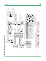
■ UT450 Position Proportional Type (Model UT450-1 or UT450-4)
<Toc> <Ind>
2-9
1st Edition : Mar. 30, 2001-00
2
3
NO
COM
SG
27
Note:Select this option from
the OT parameter.
* Time proportional PID relay contact
output is configured at factory
before shipment.
RDA(-)
26
10
9
8
Relay
AL3 4
COM 7
Alarm-3 output
Common
UT
TI 05D01C12-01E
30
10
20
19
18
17
16
15
14
13
12
11
17 -
16 +
4-20 mA DC,
voltage pulse
(12 V)
Control output
Current/voltage
pulse output
Default: 1-5 V DC
Specify in a range of
1-5 V DC, 0-2 V DC,
or 0-10 V DC.
Note:Select this
option from
the OT
parameter.
13 -
12 +
TC input
Common
Remote when R/L=ON
Local when R/L=OFF
No function
No function
No function
No function
AUTO when DI1=ON
MAN when DI1=OFF
STOP when DI2=ON
RUN when DI2=OFF
When DIS=2
Common
Common
OT=1
Time proportional control
Voltage pulse output (terminals 16 and 17 )
Current output
(terminals 16 and 17 )
OT=2
Correspondence between parameter OT and control output types
Time proportional control
Relay output (terminals 1 , 2 and 3 )
Common
4-20 mA DC
15 -
14 +
14.5-18.0VDC
(21 mA DC max.)
15 V DC loop power supply
15 -
14 +
Retransmission output
13 -
12 +
mV/V input
13 B
12 b
When DIS=4
DI3 29
COM 20
DI2 18
UT
DI1 19
Common
+5V
+5V
+5V
COM
R/L
DI3
COM
DI2
30
28
29
20
18
19
Transistor contact
DI1
Contact rating: 12 V DC, 10 mA or more
COM 30
Contact
+5V
* If 15 V DC loop power supply
is used, retransmission output
cannot be used.
Load resistance: 600 Ω or less
* PV retransmission is configured
at factory before shipment.
Remote when R/L=ON
R/L 28
Local when R/L=OFF
STOP when DI3=ON
RUN when DI3=OFF
Common
DI1 OFF ON OFF ON
DI2 OFF OFF ON ON
When switching target
SP 1 to 4:
1.SP 2.SP3.SP 4.SP
250 Ω 4-20mA
OT=3
On-off control
Relay output (terminals 1 , 2 and 3 )
F2-11.EPS
Note: Connecting a 250 Ω resistor to the terminals is
optional.
Model: X010-250-2 (resistor with M3.5 crimp-on terminal
lugs)
13 -
12 +
set the PV input type to 1-5 V DC (range code “41”).
Installation category (overvoltage category): II (IEC1010-1)
NOTE
Receiving 4-20 mA DC Current
Signals by the Controller
* When receiving 4-20 mA DC current signals,
Note: External Contact Input
If the power is turned on when the external contact input is OFF,
the mode (SPN, R/L, or A/M) existing before the power is turned
off will be continued. (except for RUN/STOP)
Common
Remote when R/L=ON
Local when R/L=OFF
STOP when DI3=ON AUTO when DI3=ON
RUN when DI3=OFF MAN when DI3=OFF
Common
2.SP when DI2=ON 2.SP when DI2=ON
1.SP when DI2=OFF 1.SP when DI2=OFF
Remote when R/L=ON
Local when R/L=OFF
OT=0 (factory-set default)
When DIS=3
AUTO when DI1=ON STOP when DI1=ON
MAN when DI1=OFF RUN when DI1=OFF
Remote when R/L=ON
Local when R/L=OFF
No function
Common
RTD input
11 A
Correspondence between parameter DIS and external contact input functions
When DIS=0 When DIS=1 (Factory-set default)
* OT is a setup parameter.
You can change the settings of the parameter OT to change the control output type.
See “2. Initial Settings,” for more information.
Relay contact rating: 240 V AC, 1 A
30 V DC, 1 A (resistance load)
Transistor contact rating: 24 V DC, 50 mA
AL2 5
AL1 6
Alarm-2 output
Alarm-1 output
Alarm output
28
29
8
9
27
26
6
7
25
24
23
22
21
5
4
3
2
1
22 -
21 +
PV input * Not configured at factory before shipment
See “2. Initial Settings,” for more
information.
* DIS is a setup parameter.
Changing DIS setpoint allows you to change the function of external contact input.
Before carrying out wiring, turn off the power
to the controller and check that cables to be
connected are not alive with a tester or the like
because there is a possibility of electric shock.
CAUTION
Allowable range: 100 to 240 V AC (10%)
(free voltage)
50/60 Hz shared
N
L
Power supply
Power supply
Contact rating: 250 V AC, 3 A
30 V DC, 3 A (resistance load)
1
NC
Relay contact output
Control output
SDA(-)
25 RDB(+)
24
23 SDB(+)
* Wiring can only be carried out for
for controllers with communication controllers with remote input.
functions.
Remote input
Maximum baud rate: 9600 bps
RS-485 communication * Wiring can only be carried out
■ UT420 Standard Type (Model UT420-0)
<Toc> <Ind>
2-10
1st Edition : Mar. 30, 2001-00
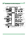
2-11
<Toc> <Ind>
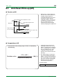
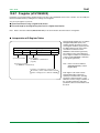
2.5
Input/Output Circuit Block Diagrams
+5V
DI6
EEPROM
Digital Input
DI1
AlarmOutput
Open Collector
DC24V/50mA
AL4
com
R/L
16bit Single Chip
com
Micro Computer
SDB(+)
Alarm Output
Relay
AC240V,DC30V/A
AL3
SDA(-)
RS485
Communication I/F RDB(+)
RDA(-)
AL2
AL1
S.G
com
~
N.C.
PV
N.O.
com
~
REM
MAN
AL1
2
3
4
+
A/M
SET/ENT
–
D/A
Converter
Loop Power Supply
DC21.6 to 28V/30mA
+
DC/DC
–
A
Control Output
Analog 4-20mA
Pulse 15V
Retransmission Output
4-20mA
or Loop Power Supply
14.5 to 18V/21mA
ASIC
b
+
B
–
A/D
Converter
PV Input
RTD/TC/mV/V
Control Output
Relay Contact
AC250V,DC30V/3A
UT450-2 Heat/Cool Type
N.C.
Control Output(Cool)
N.O.
RJC
com
~
Relay Contact
AC250V,DC30V/3A
Isolator
+
D/A
Converter
RSP Input
+
–
–
UT450-1∗/4∗ Position Proportional Type
L
Power Supply
AC100 to 240V
~
A/D
Converter
PowerDown/Freq.Det.
Feedback Input
100%
Potentiometer
(100Ω to 2.5kΩ)
FB
0%
Control Output
Relay Contact
AC250V,DC30V/3A
Open
H
C
C
Motor
L
Close
N
G
Control Output(Cool)
Analog 4-20mA
Pulse 15V
~
Switching
Power Supply
: Optical Isolator
: Relay Coil
UT450 Block Diagram
F2-12.EPS
TI 05D01C12-01E
1st Edition : Mar. 30, 2001-00
Blank Page
3-1
<Toc> <Ind>
3.
OPERATIONS
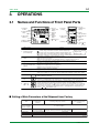
3.1
Names and Functions of Front Panel Parts
PV
1. Deviation
monitor
2. Status indicator
lamps
REM
MAN
4. Process
variable (PV)
display
3-digit LED
AL1
3. Light-loader
interface
5-digit LED
2
A/M
7. A/M key
3
4
REM MAN
5-digit LED
6. Alarm
indicator
lamps
and
YOKOGAWA
PV
3-digit LED
5. Setpoint
display
9.
SET/ENT
5. Setpoint
display
3. Light-loader
interface
AL1
2
2. Status
indicator lamps
3
6. Alarm indicator
lamps
SET/ENT
keys
A/M
8. SET/ENT
key
7. A/M key
8. SET/ENT key
4. Process
variable (PV)
display
9.
and
keys
F3-01.EPS
Name of Part
Function
When lit, indicates the status of a deviation (PV - SP).
The deviation display
range can be changed
: Is lit (in orange) if a deviation exceeds the deviation display range.
using the setup
: Is lit (in green) when a deviation is within the deviation display range.
parameter DVB .
: Is lit (in orange) if a deviation falls below the deviation display range.
The deviation monitor goes off if any display other than the operating display or SELECT display is shown.
Is lit (in green) to indicate the status of operation or control.
REM: Is lit when in remote mode.
MAN: Is lit when in manual mode. The lamp blinks when the controller is being auto-tuned.
1.
Deviation monitor
(for UT450 only)
2.
Status indicator
lamps
3.
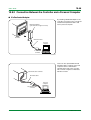
Light-loader interface
Interface for an adapter cable used when setting and storing parameters from a PC.
This requires an optional parameter setting tool.
4.
Process variable (PV)
display
Displays PV.
Displays a menu symbol when you set a parameter.
Displays an error code (in red) if an error occurs.
5.
Setpoint display
Displays a parameter symbol in 3-digit LED.
Displays the setpoint of a parameter in 5-digit LED.
6.
Alarm indicator lamps
UT450: If any of alarms 1 to 4 occurs, the respective alarm indicator lamp (AL1 to AL4) is lit (in orange).
UT420: If any of alarms 1 to 3 occurs, the respective alarm indicator lamp (AL1 to AL3) is lit (in orange).
7.
A/M key
8.
SET/ENT
key
9.
and
keys
A/M
SET/ENT
Used to switch between the AUTO and MAN modes. Each time you press the key, it switches to the
AUTO or MAN mode alternately.
Used to switch or register a parameter. Pressing the key for more than 3 seconds allows you to switch
between the operating display and the main menu for operating parameter setting display alternately.
Used to change numerical values. On setting displays for various parameters, you can change target
setpoints, parameters, and output values (in manual operation). Pressing the
key decreases a
numerical value, while pressing the
key causes it to increase. You can hold down a key to gradually
increase the speed of change. To change from the parameter setting (operating or setup) display to the
menu or from the setup parameter setting display menu to operating parameter setting display menu,
press the
and
keys simultaneously.
T3-01.EPS
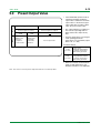
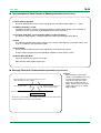
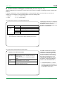
■ Setting of Main Parameters at the Shipment from Factory
Item
Remote input signal
(only for controllers
with remote inputs)
Control output
Control action
PID parameter
Alarm output
Initial values
for standard type
controllers
Initial values
for heating/cooling type controllers
Initial values for
position proportional type
controllers
1 to 5 V DC (variable)
Time proportional PID Heating side: Time proportional PID relay output (variable)
Relay output (fixed)
relay output (variable) Cooling side: Time proportional PID relay output (variable)
Reverse action (variable)
Not specified
P = 5.0%, I = 240 seconds, D = 60 seconds.
Alarm-1: PV high limit, Alarm-2: PV low limit, Alarm-3: PV high limit, Alarm-4: PV low limit
T3-02.EPS
TI 05D01C12-01E
1st Edition : Mar. 30, 2001-00
3-2
<Toc> <Ind>
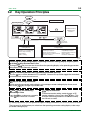
3.2
Key Operation Principles
Power ON
Display ?
IN=OFF
Operating Display
Yes
Set PV input
No
PV
PV
REM
MAN
PV
REM
MAN
AL1
2
3
4
SET/ENT
A/M
SET/ENT
key
2
3
4
AL1
SET/ENT
SET/ENT
A/M
key
SET/ENT
SP display
AUTO(automatic)/
REM
MAN
AL1
OUT display
2
3
A/M
4
MAN(manual)
A/M
Selection
SET/ENT
PID number display
SET/ENT
Press
key for more
than 3 seconds
or
key
Password
Verification
Operating Parametter
Setting Display
• Alarm value setting
• Remote / Local switching
• Run / Stop switching
• PID setting
• Other setting
Setup Parametter
Setting Display
• Target SP relations
• Alarm type relations
• Control Action relations
• Retransmission output relations
• Security relations
• Select display relations
• Input/Output relations
• Communication relations
• Valve relations
• Parameter Initialization
F3-02.EPS
Transferring to the Operating Display / Operating Parameter Setting Display requires pressing of the
Key for more than 3 sec.
SET/ENT
Pressing the
key for more than 3 sec allows the operating display or the operating parameter
setting display to be alternately selected.
SET/ENT
A/M
Key for switching between AUTO (Automatic) and MAN (Manual)
Press the
key to switch between AUTO and MAN. Successive keystrokes toggle the mode back
and forth between automatic and manual.
A/M
SET/ENT
Key for selecting a Parameter
With the operating parameter setting display or the setup parameter setting display shown, each
press of the
key changes a parameter item.
SET/ENT
and
Keys for increasing /
decreasing a value
Press the
key to decrease a numeric
or the
key to increase a numeric.
SET/ENT
Key for execution
To execute numeric setting, mode change, or SP
number selection, always press the
key. This
changes the existing numeric or mode to the newly
set numeric or mode.
SET/ENT
By setting a password, you can prevent changes to setup parameters. (See 10.4 Security Function for details.)
The password is verified when you switch from the operating parameter setting display to the setup
parameter setting display.
TI 05D01C12-01E
1st Edition : Mar. 30, 2001-00
3-3
<Toc> <Ind>
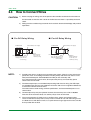
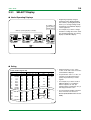
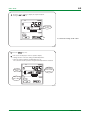
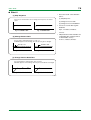
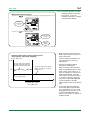
3.3
Operating Display
• Pressing the
key for more than 3 seconds on the operating display to move to the operating
parameter setting display.
SET/ENT
• Pressing the
key for more than 3 seconds on the operating parameter setting display causes
the operating display 1 to appear.
SET/ENT
• Switching from the MAN mode to AUTO causes the operating display
1
to appear.
• Switching from the AUTO mode to MAN causes the operating display
2
to appear.
• Each time the
key is pressed, the operating display changes in the order of
SET/ENT
1
,
2
,
3
,
1
, .....
• The upper large display area always displays process variables.
• The lower right and left display areas change as follows and can be suitably used as needed.
Power ON
Pressing the SET / ENT key for more than 3 seconds
on the operating parameter setting display
Note
Operating Display 1
SP display
Switching to AUTO
PV
Measured value
REM
MAN
AL1
2
3
4
A/M
SET/ENT
SET/ENT
Setpoint (engineering unit)
“Setpoint number” symbol (Example of 1.SP)
Operating Display 2
OUT display
• OUT display for Heating/Cooling type
SET/ENT
“Output”
symbol
Operating Display 3
Control output (%)
Cooling side
output
Heating-side
output
PID number display
SET/ENT
PID number
Note: Set PV input type first, when the “IN = OFF” display is appeared.
F3-03.EPS
TI 05D01C12-01E
1st Edition : Mar. 30, 2001-00
3-4
<Toc> <Ind>
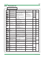
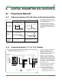
3.3.1
SELECT Display
● Useful Operating Displays
Useful
operating display
(SELECT display)
• For example, if you want to change
the Alarm-1 setting value often, select
the operating parameter “A1” setting
display as a SELECT display.
Ordinary operating displays (example)
PV
PV
PV
REM
MAN
REM
MAN
REM
MAN
AL1
2
3
4
AL1
SET/ENT
A/M
SET/ENT
SP display
key
2
3
4
PV
REM
MAN
AL1
SET/ENT
A/M
key
SET/ENT
2
3
4
AL1
SET/ENT
A/M
PID number display
SET/ENT
key
2
3
4
A/M
SET/ENT
SET/ENT
OUT display
• Registering frequently changed
parameters in the SELECT display
after ordinary operating displays will
allows you to change settings easily.
A maximum of five SELECT displays
can be registered.
“A1” setting
display (example)
key
F3-03-01.EPS
● Seting
UT450, UT420 D-register Map
PROCESS
PROGRAM
No.
1~
No. 51~ No. 101~ No. 151~
1 ADERROR 51
101
151
2
52
102
152
ERROR
3
53
103
153
PV
4
54
104
154
CSP
5
55
105
155
OUT
6
56
106
156
HOUT
7
57
107
157
COUT
8
58
108
158
MOD
9
59
109
159
PIDNO
10
60
110
160
CSPNO
28
178
11
61
111
161
ALM
29
79
129
179
30
80
130
180
31
81
131
181
82
132
182
32
33
83
133
183
DISTS
34
84
134
184
35 PARAERR 85
135
185
No.
201
202
203
204
205
206
207
208
209
227
210
228
229
230
231
232
233
234
235
MODE/PAR
201~
No. 251~
251 ORH
A/M
252 ORL
253
R/L
254
255
S/R
256
257
SPN
258
259
277
260
278
279
280
281
A1
282
A2
283
A3
284
A4
285
• Setup parameters “C.S1”, “C.S2”,
“C.S3”, “C.S4” and “C.S5” are used to
set the SELECT displays.
• For parameters “C.S1” to “C.S5”, set
a number on the D-register map to
specify the parameter you want to
register.
• For example, if you want to make a
SELECT display-1 for setting the
Alarm-1 setpoint, set “231” (Dregister number of parameter “A1”) to
the setup parameter “C.S1”.
• For any D register number other than
those on the left, see the User’s
Manual (IM 05J01B02-01E in the CDROM).
F3-03-02.EPS
TI 05D01C12-01E
1st Edition : Mar. 30, 2001-00
3-5
<Toc> <Ind>
3.4
PARAMETERS
3.4.1
Parameter Setting Flow
Power ON
Operating
Display
Menu
Press
SET/ENT
SET/ENT
No
Display ?
IN=OFF
All operating parameters are displayed in the order
of this flow chart, Note that some parameters are
displayed only under special condition.
Yes
Determine PV
input type first
Menu
key for 3sec or more
Operating Parameter Setting Display
key
Alarm-2
setpoint
To switch the parameter display, press the
SET/ENT
Displayed only when
password registration
key.
Password input
(No password is required
when PWD = 0.)
Alarm-3
setpoint
Alarm-4
setpoint
Remote/local
switching
SET/ENT
Displayed only with UT450-1 or -3
Displayed when setup
parameter “DIS = 0”
Auto-tuning
Displayed in automatic
operation
See the next page
Pressing the
key when
PID = 1Gr causes PID
for 1.SP to appear.
SUPER function
SET/ENT
Target setpoint
number selection
key
B
Displayed only for controllers
with remote input
Run/stop
switching
Pressing the
key when
PID = 8Gr causes PID
for 8.SP to appear.
SET/ENT
The setpoints (5.SP to 8.SP) are not displayed
in the initial setting
To use 5.SP to 8.SP,
set setup parameter “GRP = 5 to 8”.
Proportional band /
heating-side
proportional band
PID parameter
display number
FL is displayed if you
press the
key
when PID = MENU.
SET/ENT
Integral time / heating-side
integral time
PV input filter
Derivative time /
heating-side
derivative time
PV input bias
Output high limit /
heating-side output
high limit
Setpoint
ramp-up rate
Not displayed for
ON/OFF control
Output low limit /
cooling-side output
high limit
Setpoint
ramp-down rate
Manual reset
Ratio setting
Remote
input bias
key
SET/ENT
Alarm-1
setpoint
Displayed only for
controllers with
remote input
Remote
input filter
ON/OFF control
hysteresis / heating-side
ON/OFF control hysteresis
Displayed for ON/OFF
control
Direct/reverse
action switching
Cooling-side
proportional band
ON/OFF rate
detection band
Cooling-side integral time
ON/OFF rate
high limit
Cooling-side derivative time
ON/OFF rate
low limit
Cooling-side
ON/OFF control hysteresis
Target
setpoint-1
Dead band
Target
setpoint-2
Preset output / heating-side
preset output
Target
setpoint-3
Cooling-side preset output
Displayed for
heating/cooling control
Displayed for heating/cooling
control or position proportional
PID control
Displayed for heating/cooling
control
Target
setpoint-4
Target
setpoint-5
Target
setpoint-6
Not displayed in the initial
setting
Target
setpoint-7
To use 5.SP to 8.SP, set setup
parameter “GRP = 5 to 8”
Target
setpoint-8
F3-04.EPS
TI 05D01C12-01E
1st Edition : Mar. 30, 2001-00
key
or
Deviation
display band
Target setpoint
limiter
lower limit
Ramp-rate
time unit
Target setpoint
limiter
upper limit
SET/ENT
key
Press this key for
more than 3 seconds
to move to the
operating
display.
Note
key
key
PID group
number
Zone PID
reference
point-1
Alarm-3
hysteresis
Alarm-4
hysteresis
Alarm mode
Alarm-4
delay timer
Alarm-3
delay timer
Alarm-2
delay timer
Reference
deviation
Zone switching
hysteresis
Zone PID
reference
point-6
Zone PID
reference
point-3
Zone PID
reference
point-4
Zone PID
reference
point-5
Zone PID
reference
point-2
Restart
timer
Alarm-1
delay timer
Restart
mode
Alarm-2
hysteresis
Anti-reset
windup
PID control
mode
Alarm-1
hysteresis
key
or
key
or
key
SET/ENT
key
SET/ENT
or
key
Lock of
Remote/Local
selection
parameter
Lock of
parameter for
PID parameter
display
numbers
Password
setting
Front panel
A/M key lock
Front panel
data setting
( , ) key lock
key
Sets the display group number of
operating parameter PIDs.
Maximum
value of
retransmission
output scale
Minimum
value of
retransmission
output scale
Retransmission
output type
key
Security
SET/ENT
SET/ENT
key
SET/ENT
SELECT
display
To switch parameter display,
press the
key.
Displayed when parameter “ZON = 1”
SET/ENT
SET/ENT
Retransmission
output related
Output
velocity limiter
key
Zone PID
selection
SET/ENT
SET/ENT
Control action
related
Alarm-4 type
Alarm-3 type
key
Alarm-2 type
SET/ENT
or
key
PV tracking
selection
SET/ENT
SP tracking
selection
key
Alarm-1 type
key
Remote input
selection
Parameter RMS and SPT are
displayed only for controllers
with remote input.
SET/ENT
SET/ENT
Alarm related
Menu
key
key
SELECT
display-1
registration
SELECT
display-2
registration
SELECT
display-3
registration
SELECT
display-4
registration
SELECT
display-5
registration
key
or
or
SET/ENT
key
key
or
key
TI 05D01C12-01E
DI function
selection
Cooling-side
control output
cycle time
Control output
cycle time /
heating-side
control output
cycle time
Control output
type
Selection of
non-display of
figures below
PV input
decimal point
Minimum
value of
remote
input scale
Maximum
value of
remote input
scale
Remote input
type
(RSP INPUT
terminals)
Presence/
absence of PV
input reference
junction
compensation
Selection of
PV input
burnout action
Minimum
value of PV
input scale
(displayed at
voltage input)
Maximum
value of PV
input scale
(displayed at
voltage input)
PV input
decimal point
position
(displayed at
voltage input)
PV input
unit
Maximum
value of PV
input range
Minimum
value of PV
input range
A
key
Minimum
response time
Address
Data length
Stop bit
Parity
Baud rate
SET/ENT
key
SET/ENT
Not displayed for position
proportional controllers
or
key
Automatic
valve
adjustment
key
key
key
Parameter
initialization
Displayed in manual
operation
SET/ENT
SET/ENT
Parameter
initialization
Displayed only for position
proportional controllers
Valve
traveling time
Valve
adjusting
mode
Fully-closed
valve position
setting
Fully-opened
valve position
setting
Valve position
setting reset
Displayed only for controllers
with communication feature
key
or
Protocol
selection
key
Displayed only for controllers
with remote input
SET/ENT
SET/ENT
Valve related
Displayed first after power on
Communication
PV input type
(PV INPUT
terminals)
SET/ENT
Input/output
related
To Operating Parameter setting Display
Setup Parameter Setting Display
Note
3.4.2
Target
setpoint
related
B
<Toc> <Ind>
3-6
Setup Parameter Setting Flow
F3-05.EPS
1st Edition : Mar. 30, 2001-00
3-7
<Toc> <Ind>
3.4.3
Parameter List
Operating Parameter (1/2)
Parameter
Symbol
Name of Parameter
Setting Range and Description
Initial Value
PV alarm / SP alarm: -100.0 to
100.0% of PV input range
Deviation alarm: -100.0 to 100.0%
of PV input range span
Output alarm: -5.0 to 105.0%
Timer alarm (for alarm 1 only):
0.00 to 99.59 (hour. min) or
(min. sec)
These Alarm setpoint parameters
are common to the parameters
1.SP to 8.SP.
PV high limit/SP high limit
alarm: 100.0% of PV
input range
Deviation alarm: 0.0% of
PV input range span
Other PV/SP low limit alarm:
0.0% of PV input range
Output high limit alarm: 100.0%
Output low limit alarm: 0.0%
REM: remote operation
LCL: local operation
LCL
Run/stop switching
Stop: operation stopped
Run: operation started
RUN
Auto-tuning
OFF: No auto-tuning
1 to 8: Auto-tuning for 1.SP to 8.SP
9: Performs auto-tuning to all groups 1 to 8.
OFF: Disable
1: Overshoot suppressing function
2: Hunting suppressing function
(Stable mode)
3: Hunting suppressing function
(Response mode)
1 to 8:
Select target setpoint 1 (1.SP) to 8 (8.SP)
OFF
Alarm 1-setpoint
(A1)
Alarm 2-setpoint
(A2)
Alarm 3-setpoint
(A3)
Alarm 4-setpoint
(A4)
Remote/local switching
User Setting
P.10-6
(S/R)
“Super” function
(SC)
Target setpoint
number selection
P.10-10
P.10-2
(R/L)
(AT)
Reference
Page
P.6-1
OFF
P.7-1
to
P.7-2
1
P.9-1
(SPN)
PID parameter display
number
(PID)
PV input filter
MENU: Move to FL parameter display MENU
1Gr to 8Gr: Display of each PID
parameter (factory-set to 1Gr to 4Gr)
OFF, 1 to 120 sec
OFF
Used when the PV input fluctuates.
P.8-1
P.4-7
(FL)
PV input bias
(BS)
Setpoint ramp-up-rate
(UPR)
Setpoint ramp-downrate
(DNR)
Ratio setting
(RT)
Remote input bias
-100.0% to 100.0% of PV input
range span
Used to adjust the PV input value.
OFF
0.0% + 1 digit of PV input range span
to 100.0% of PV input range span
Set ramp-up-rate or ramp-down-rate
per hour or minute.
Sets unit in ramp-rate-time unit (TMU).
0.001 to 9.999
Target setpoint = Remote input
Ratio setpoint + Remote bias
-100.0 to 100.0% of PV input
range span
0.0% of PV input range
span
P.4-6
OFF
P.9-2
OFF
1.000
0.0% of PV input range
span
P.4-7
P.10-17
(RBS)
Remote input filter
OFF, 1 to 120 sec.
OFF
P.10-16
(RFL)
ON/OFF rate detection
band
0.0 to 100.0% of PV input range
span
1.0% of PV input range
span
ON/OFF rate high limit
[ORL + 1 digit] to 105.0%
100.0%
(ORB)
P.10-12
(ORH)
ON/OFF rate low limit
-5.0% to [ORH - 1 digit]
0.0%
(ORL)
T3-03-1.EPS
TI 05D01C12-01E
1st Edition : Mar. 30, 2001-00
3-8
<Toc> <Ind>
Operating Parameter (2/2)
Parameter
Symbol
Name of Parameter
Target setpoint-1
(1.SP)
Target setpoint-8
(8.SP)
(1.P)
(1.I)
(1.D)
(1.OH)
(1.OL)
•Proportional band
•Heating-side proportional
band (in heating/cooling
control)
Integral time
Heating-side integral time
(in heating/cooling control)
Derivative time
Heating-side derivative time
(in heating/cooling control)
Output high limit
Heating-side output high
limit (in heating/cooling
control)
Output low limit
Cooling-side output high
limit (in heating/cooling
control)
Manual reset
(1.MR)
(1.H)
ON/OFF control
hysteresis
Heating-side ON/OFF
control hysteresis
Direct/reverse action
switching
Setting Range and Description
0.0 to 100.0% of PV input range
However, between target setpoint
limiter lower limit (SPL) and upper
limit (SPH).
Note: The 5.SP to 8.SP are not
displayed in the initial setting.
To display them, set setup parameter
GRP (PID set number) to the number
you wish to display.
Initial Value
User Setting
Reference
Page
0.0% of PV input
range
P.9-1
0.1 to 999.9%
5.0%
In heating/cooling control: 0.0 to 999.9%
(heating-side ON/OFF control applies
when 0.0)
OFF, 1 to 6000 sec.
240 sec.
P.8-1
P.8-2
OFF, 1 to 6000 sec.
60 sec.
P.8-3
-5.0 to 105.0%
Heating-side limiter in heating/cooling
control: 0.0 to 105.0% (1.OL < 1.OH)
100%
Heating/cooling control:
100.0%
-5.0 to 105.0%
Cooling-side limiter in heating/cooling
control: 0.0 to 105.0% (1.OL < 1.OH)
SD (shutdown): Set in manual
operation in 4-20 mA control output.
The control output is set at 0 mA.
-5.0 to 105.0%
(enabled when integral time “1.I” is OFF)
The manual reset value equals the
output value when PV = SP is true.
In ON/OFF control: 0.0 to 100.0%
of PV input range span
Position proportional PID control
or heating/cooling control: 0.0 to
100.0%
RVS: reverse action, DIR: direct action
0.0%
Heating/cooling control:
100.0%
P.5-11
50.0%
P.8-2
ON/OFF control: 0.5% of
PV input range span
Position proportional PID
control and heating/cooling
control: 0.5%
RVS
P.5-7
P.5-10
(1.DR)
Cooling-side
proportional band
(1.Pc)
Cooling-side integral
time
0.0 to 999.9%
(Cooling-side ON/OFF control
applies when 0.0)
OFF, 1 to 6000 sec
5.0%
P.5-8
P.8-1
240 sec.
P.8-2
(1.Ic)
Cooling-side derivative
time
OFF, 1 to 6000 sec
Cooling-side ON/OFF
control hysteresis
0.0 to 100.0%
60 sec.
P.8-3
(1.Dc)
0.5%
P.5-7
(1.Hc)
Dead band
(1.DB)
(1.PO)
(1.Oc)
In heating/cooling control: -100.0 to 50.0%
In position proportional PID control: 1.0 to
10.0% (*See P.5-6)
-5.0 to 105.0%
Preset output/HeatingIn heating/cooling control:
side preset output
(in heating/cooling control) Heating side 0.0 to 105.0%
In Stop mode, fixed control output
can be generated.
Cooling-side preset
0.0 to 105.0%
output
In Stop mode, cooling-side fixed
control output can be generated.
3.0%
P.5-6
P.5-8
0.0%
P.5-12
P.11-4
0.0%
The PID-related parameters in the above chart are displayed when “1Gr” is set to PID parameter display number (PID). In this case, the
corresponding target setpoint is 1.SP (target setpoint-1).
To set PID corresponding to target setpoint 2 to 4, set “2Gr”, “3Gr”, or “4Gr” to PID. The relevant parameters will then be displayed.
T3-03-2.EPS
TI 05D01C12-01E
1st Edition : Mar. 30, 2001-00
3-9
<Toc> <Ind>
Setup Parameter (1/4)
Related Parameter
Function
Symbol
Name of Parameter
Remote input selection
(RMS)
SP tracking selection
Target Setpoint
(SPT)
PV tracking selection
(PVT)
Ramp-rate time unit
setting
(TMU)
Target setpoint limiter
upper limit
(SPH)
Target setpoint limiter
lower limit
Setting Range and Description
Initial Value
RSP: Remote setpoints are used via remote input
RSP
(terminals).
COM: Remote setpoints are used via communication.
OFF, ON
ON
Tracking is performed when the mode changes
from Remote to Local (the local setpoint keeps
track of the remote setpoint).
OFF
OFF, ON
Uses a combination of the setpoint ramp-up (UPR) and
setpoint ramp-down (DNR) parameters.
HOUR, MIN
Time unit of setpoint ramp-up (UPR) and setpoint
ramp-down (DNR)
0.0 to 100.0% of PV input range
where, SPL < SPH
Places a limit on the range within which the
target setpoint is changed.
User Setting
Reference
Page
P.10-16
P.10-1
HOUR
P.9-2
100.0% of
PV input range
0.0% of
PV input range
P.9-1
(SPL)
Deviation display band
(UT450 only)
0.0 to 100.0% of PV input range span
Alarm-1 type
OFF, 1 to 31
See page for timer function.
Alarm-2 type
OFF, 1 to 20, 25 to 31
2
Alarm-3 type
These Alarm Type parameters are common to the
parameters 1.SP to 8.SP.
1
(DVB)
1.0% of PV
input range
span
1
—
(AL1)
(AL2)
P.10-9
(AL3)
Alarm-4 type
2
(AL4)
Alarm-1 hysteresis
0.0 to 100.0% of PV input range span
Output alarm: 0.0 to 100.0%
(HY1)
Alarm-2 hysteresis
0.5% of PV
input range span
Output alarm:
0.5%
Alarms
(HY2)
P.10-10
Alarm-3 hysteresis
(HY3)
Alarm-4 hysteresis
(HY4)
Alarm-1 delay timer
0.00 to 99.59 (min, sec.) (enabled when alarmn type “ALn” is 1 to 20 or 28 to 31)
(n=1 to 4)
Alarm-2 delay timer
An alarm is output when the delay timer expires
after the alarm setpoint is reached.
(DY1)
0.00
(DY2)
—
Alarm-3 delay timer
(DY3)
Alarm-4 delay timer
(DY4)
Alarm mode
(AMD)
Allows the alarm function to be enabled or disabled
according to the operating condition.
0: Always active
1: Not active when in Stop mode
2: Not active when in Stop mode or manual operation
0
—
T3-04-1.EPS
TI 05D01C12-01E
1st Edition : Mar. 30, 2001-00
3-10
<Toc> <Ind>
Setup Parameter (2/4)
Related Parameter
Function
Symbol
Name of Parameter
Setting Range and Description
Output velocity limiter
OFF (0)
0.1 to 100.0%/sec
can limit control output velocity
0: Standard PID control (with output bump at SP change)
1: Fixed point control (without output bump at SP change)
Choose “Fixed Point Control” when controlling pressure
or flow rate.
AUTO (0), 50.0 to 200.0%
Used when the control output travels up to
100% or down to 0% and remains there.
The larger SP, the sooner PID computation
(integral computation) stops.
0: SP selection
1: Zone PID
(OPR)
PID control mode
(MOD)
(AR)
Anti-reset windup
(Excess integration
prevention)
Zone PID selection
Initial Value
User Setting
Reference
Page
OFF
P.5-11
0
P.10-3
AUTO
P.8-5
0
P.8-6
(ZON)
Control Action
Restart mode
(R.MD)
Restart timer
(R.TM)
PID group number
(GRP)
Zone PID reference
point-1
(1.RP)
CONT: Continues action set before power failure.
MAN: Starts from manual operation status
AUTO: Continues action set before power failure
in automatic operation.
0 to 10 sec.
Sets time between power on and the
instant where controller starts computation.
1 to 8
Determines operating parameter PID display
group number.
0.0 to 100.0% of PV input range.
Note that 1.RP 2.RP 3.RP 4.RP 5.RP 6.RP.
CONT
P.11-3
0 sec.
—
4
P.8-1
100% value of
PV input range
Set Zone PID selection (ZON) parameter to “1”.
UT450/420 has six
reference point-1 to -6.
Zone PID reference
point-6
P.8-6
(6.RP)
Zone switching
hysteresis
(RHY)
Reference deviation
Retransmission
Output
(RDV)
Retransmission output
type
(RET)
(RTH)
(RTL)
0.0 to10.0% of PV input range span
Allows a hysteresis to be set for switching
at a reference point.
OFF, 0.0 to100.0% of PV input range span
Used to select PID constants according to a deviation from
the setpoint. The maximum group of PID constants is used
when the controller fails to keep track of the deviation.
OFF: Disable
1: PV, 2: SP , 3: OUT
4: Loop power supply for sensor (15 V)
Max. value of
RET=1, 2: [RTL + 1 digit] to 100.0% of PV
retransmission output
input range
scale
RET=3: [RTL + 1 digit] to 100.0%
Min. value of
RET=1, 2: 0.0% of PV input range to
retransmission output
[RTH - 1 digit]
scale
RET=3: 0.0% to [RTH - 1 digit]
Front panel data setting OFF, ON
( , ) key lock
0.5% of PV
input range
span
OFF
1
100.0% of
PV input range
P.10-18
0.0% of
PV input range
OFF
Security
(DAT)
Front panel A/M key
lock
OFF, ON
OFF
Lock of Remote/Local
selection parameter
OFF, ON
OFF
Lock of parameter for
PID parameter display
number
Password setting
OFF, ON
OFF
0: Password not set
1 to 30000
0
(A/M)
(R/L)
(PID)
(PWD)
P.10-15
P.10-14
T3-04-2.EPS
TI 05D01C12-01E
1st Edition : Mar. 30, 2001-00
3-11
<Toc> <Ind>
Setup Parameter (3/4)
Related Parameter
Function
Symbol
Name of Parameter
SELECT display-1
registration
SELECT Display
(C.S1)
SELECT display-2
registration
(C.S2)
SELECT display-3
registration
(C.S3)
SELECT display-4
registration
(C.S4)
SELECT display-5
registration
Initial Value User Setting
Setting Range and Description
OFF, 201 to 1023
Reference
Page
OFF
Select the desired parameter from among the operating
and setup parameters, then register the number
(D register No.) accompanying that parameter.
For example, registering “231” for C.S1 allows you to
change alarm-1 setpoint in operating display.
P.3-4
Numbers for registering alarm SP parameter for
operating display:
Alarm-1 setpoint: 231
Alarm-2 setpoint: 232
Alarm-3 setpoint: 233
Alarm-4 setpoint: 234
Above numbers are alarm setpoint parameters for
target setpoint-1 (1.SP).
(C.S5)
PV input type
OFF, 1 to 18, 30, 31, 35 to 37, 40, 41, 50, 51, 55, 56
(See Instrument Input Range Codes)
OFF
%: Percent
F: Fahrenheit
C: degree Celsius
-: No unit
Instrument input range, however RL < RH
-Temperature input
Set the range of temperature that is actually controlled.
- Voltage input
Set the range of a voltage signal that is applied.
The scale across which the voltage signal is actually
controlled should be set using the parameters
Maximum Value of PV Input Scale (SH) and Minimum
Value of PV Input Scale (SL).
0 to 4
Set the position of the decimal point of voltagemode PV input.
-19999 to 30000, however SL < SH
Set the read-out scale of voltage-mode PV input.
C
P.4-2
(IN)
PV input unit
(UNI)
Max. value of PV input
range
(RH)
Min. value of PV input
range
(RL)
(DP)
Input / Output
(SH)
(SL)
(BSL)
(RJC)
PV input decimal point
position (displayed
at voltage input)
Max. value of PV input
scale
(displayed at voltage input)
Min. value of PV input
scale
(displayed at voltage input)
Selection of PV input
OFF
burnout action
UP: Up scale
DOWN: Down scale
Presence/absence of
OFF, ON
PV input reference
junction compensation
Remote input type
40, 41, 50, 51
P.4-3
Max. value of
instrument
input range
Min. value of
instrument
input range
P.4-4
2
100.00
0.00
P.4-5
-
P.4-6
41
(RSP)
Max. value of remote
setting input scale
(RSH)
Min. value of remote
setting input scale
-19999 to 30000
However, RSL < RSH
Set RSL and RSH in a range of RL to RH or
SL to SH.
(RSL)
(DPC)
(OT)
(CT)
Selection of non-display
OFF, ON
of figures below PV input For second decimal place, figures up to the
decimal point
first decimal place are shown.
Control output
0 to 12
type
Note:The setting ralue 4 to 12 are displayed
only for heating/ cooling type controllers.
Control output cycle time 1 to 1000 sec.
Heating-side control
output cycle time in
heating/cooling control
Cooling-side control
1 to 1000 sec.
output cycle time
Max. value of
PV input range
or that of PV
input scale
Min. value of
PV input range
or that of PV
input scale
OFF
P.10-16
—
0
Heating/cooling
type: 4
30 sec.
30 sec.
P.5-1
P.5-2
(CTc)
DI function selection
0,1,2,3 or 4
P.10-4
(DIS)
T3-04-3.EPS
TI 05D01C12-01E
1st Edition : Mar. 30, 2001-00
3-12
<Toc> <Ind>
Setup Parameter (4/4)
Related Parameter
Function
Symbol
Name of Parameter
Protocol selection
Communication
(PSL)
Baud rate
Setting Range and Description
0: PC link communication
1: PC link communication (with sum check)
2: Ladder communication
3: Coordinated master station
4: Coordinated slave station
7: MODBUS (ASCII)
8: MODBUS (RTU)
10: Coordinated slave station (loop-1 mode)
11: Coordinated slave station (loop-2 mode)
600, 1200, 2400, 4800, 9600 (bps)
Initial Value
User Setting
Reference
Page
0
9600
(BPS)
Parity
(PRI)
Stop bit
NONE: None
EVEN: Even
ODD: Odd
1, 2
EVEN
P.10-20
to
P.10-44
1
(STP)
Data length
(DLN)
Address
(ADR)
Minimum response
time
7, 8:
8
Fixed at 7, in MODBUS (ASCII) communication.
Fixed at 8, in MODBUS (RTU) and Ladder
communication.
1 to 99
1
However, the maximum number of stations
connectable is 31.
0 to 10 ( 10 ms)
0
Valve Calibration (Position Proportional Controlllers only)
(RP.T)
Automatic valve
adjustment
(V.AT)
Valve position setting
reset
(V.RS)
Fully-closed valve
position setting
(V.L)
Fully-opened valve
position setting
(V.H)
Valve traveling time
(TR.T)
Valve adjusting mode
(V.MD)
Automatically adjusts the fully-shut and fully-open positions
of a valve. When this function is used, there is no need for
adjustment using the parameters V.RS, V.L and V.H.
OFF: ON: Start automatic adjustment
The parameters V.RS, V.L and V.H are designed for
manual adjustment of valve positions.
Setting V.RS to 1 resets the valve adjustment
settings and causes the indication “V.RS” to blink.
Pressing the SET/ENT key with valve position
set to the fully-closed position causes the
adjusted value to be stored. When V.L
adjustment is complete, V.L stops blinking.
Pressing the SET/ENT key with valve position
set to the fully-opened position causes the
adjusted value to be stored. When V.H
adjustment is complete, V.H stops blinking.
5 to 300 sec
Used to operate a valve according to the estimated
valve position. Set the time required for the valve to
open fully from a state of being fully shut. Confirm
the valve traveling time by consulting the datasheet
of the valve’s specifications.
The valve traveling time is only effective when
Valve Adjustment Mode (V.MD) is set to 1 or 2.
0: Valve position feedback type
1: Valve position feedback type (moves to the
estimating type if a valve input error or burnout
occurs.)
2: Valve position estimating type
OFF
0
Undefined
Undefined
P.5-5
60 sec.
0
T3-04-4.EPS
TI 05D01C12-01E
1st Edition : Mar. 30, 2001-00
4-1
<Toc> <Ind>
4.
MEASURED INPUT
4.1
Universal Input
● Selectable among TC, RTD, mV
and DC voltage.
Universal Inputs
TC
mv
V
4 to 20mA current
The type of input signal and input
range can be changed at the
customer side by some key operation
or by using LL100 parameter setting
tool.
● 0.1% Indication Accuracy.*
* Refer to the chart on the next page.
Voltage pulse
RTD
Relay contact
2-wire
transmitter
Motor operated valve
Universal Control Outputs*
F4-01.EPS
* See Page 5-1 for the information of Universal Output.
2-wire transmitter: FP201
● Connectable up to two 2-wire trans
mitters simultaneously.
UT450/420 has a 15V loop Supply
(15V LPS) for a transmitter.
Moreover, 24V LPS is also available
simultaneously as optional function.
Applicable models for 24V LPS:
UT450 – 3
or
UT450 – 4
UT450 -3
and
UT450 -4
*UT420 has no 24V LPS function.
2-wire transmitter: EJA
F4-02.EPS
TI 05D01C12-01E
1st Edition : Mar. 30, 2001-00
4-2
<Toc> <Ind>
■ Instrument Input Range Codes
Input
Type
Unspecified
Instrument Input
Range Code
OFF
1
K
2
3
J
4
5
T
6
B
7
S
8
R
9
N
10
E
11
L(DIN)
12
Thermocouple
13
U(DIN)
14
W
15
Platinel 2
16
PR20-40
17
W97Re3W75Re25
18
30
JPt100
31
35
RTD
Pt100
36
0.4 to 2 V
1 to 5 V
0 to 2 V
0 to 10 V
-10 to 20 mV
0 to 100 mV
40
41
50
51
55
56
37
Standard
signal
DC voltage
Instrument
Measurement Accuracy
Input Range
Set the data item PV Input Type "IN" to the OFF option to leave the PV input
type undefined.
-270.0 to 1370.0°C
-450.0 to 2500.0F
-270.0 to 1000.0°C
-450.0 to 2300.0F 0.1% of instrument range 1 digit at 0°C or more
-200.0 to 500.0°C
0.2% 1 digit for temperatures below 0°C,
-200.0 to 1000.0F where the accuracy is: 2% of instrument range 1
-200.0 to 1200.0°C digit for temperatures below -200.0°C for a type-K thermo-300.0 to 2300.0F couple, or 1% of instrument range 1 digit for
temperatures below -200.0°C for a type-T thermocouple.
-270.0 to 400.0°C
-450.0 to 750.0F
0.0 to 400.0°C
-200.0 to 750.0F
0.0 to 1800.0°C 0.15% of instrument range 1 digit at 400°C or more
5% of instrument range 1 digit at less than 400°C
32 to 3300F
0.0 to 1700.0°C
32 to 3100F
0.15% of instrument range 1 digit
0.0 to 1700.0°C
32 to 3100F
0.1% of instrument range 1 digit
-200.0 to 1300.0°C
0.25% of instrument range 1 digit for temperatures
-300.0 to 2400.0F
below 0°C
-270.0 to 1000.0°C
-450.0 to 1800.0F
-200.0 to 900.0°C
0.1% of instrument range 1 digit at 0°C or more
-300.0 to 1600.0F 0.2% 1 digit for temperatures below 0°C, where the
accuracy is:1.5% of instrument range 1 digit for
-200.0 to 400.0°C
temperatures below -200.0°C for a type-E thermocouple.
-300.0 to 750.0F
0.0 to 400.0°C
-200.0 to 1000.0F
0.0 to 2300.0°C
0.2% of instrument range 1 digit
32 to 4200F
0.0 to 1390.0°C
0.1% of instrument range 1 digit
32.0 to 2500.0F
0.0 to 1900.0°C 0.5% of instrument range 1 digit at 800°C or more
No accuracy is guaranteed at less than 800°C
32 to 3400F
0.0 to 2000.0°C
0.2% of instrument range 1 digit
32 to 3600F
-200.0 to 500.0°C
0.1% of instrument range 1 digit (Note 1) (Note 2)
-300.0 to 1000.0F
-150.00 to 150.00°C
0.2% of instrument range 1 digit (Note 1)
-200.0 to 300.0F
-200.0 to 850.0°C
-300.0 to 1560.0F
0.1% of instrument range 1 digit (Note 1) (Note 2)
-200.0 to 500.0°C
-300.0 to 1000.0F
-150.00 to 150.00°C
0.2% of instrument range 1 digit (Note 1)
-200.0 to 300.0F
0.400 to 2.000 V
1.000 to 5.000 V
0.1% of instrument range 1 digit
0.000 to 2.000 V
Display range is scalable in a range of -19999 to 30000.
0.00 to 10.00 V
Display span is 30000 or less.
-10.00 to 20.00 mV
0.0 to 100.0 mV
T4-01.EPS
*
Note 1:
Note 2:
*
Performance in the standard operating condition (at 23±2°C, 55±10%RH, and 50/60 Hz power frequency)
The accuracy is ±0.3°C of instrument range ±1 digit for a temperature range from 0°C to 100°C.
The accuracy is ±0.5°C of instrument range ±1 digit for a temperature range from -100°C to 200°C.
To receive a 4-20 mA DC signal, select a standard signal of 1 to 5 V DC and connect it to a 250 Ω resistor.
This resistor is optional. Model: X010-250-2 (resistor with M3.5 crimp-on terminal lugs)
TI 05D01C12-01E
1st Edition : Mar. 30, 2001-00
4-3
<Toc> <Ind>
4.2
Measured Input Related Parameters
PV input type
(PV INPUT
terminals)
PV input
unit
(IN)
(UNI)
Maximum Minimum
PV input
value of PV value of PV decimal point
input range input range
position
(displayed at
voltage input)
(RH)
(RL)
(DP)
Maximum
value of PV
input scale
(displayed at
voltage input)
Minimum
Selection of
Presence/
value of PV
PV input absence of PV
input scale burnout action input reference
(displayed at
junction
voltage input)
compensation
(SH)
(SL)
(BSL)
• The setup parameters (measured
input relations) include the
parameters shown at the left.
(RJC)
F4-03.EPS
4.3
PV Input Unit
• The PV input unit can be set using
the setup parameter “UNIT”.
% : Percent
˚C : Degree Celsius
(Initial Value)
˚F : Fahrenheit
– : No unit
F4-04.EPS
● Unit Label
Attach a necessary
unit label.
PV
• The UT450/420 is provided with unit
labels. Attach a desired unit label at
the display unit. If there is no relevant
unit label, enter the desired unit in a
blank label for use.
˚C
REM
MAN
AL1
2
3
4
A/M
SET/ENT
Enter desired units
here if necessary
Unit label
F4-05.EPS
TI 05D01C12-01E
1st Edition : Mar. 30, 2001-00
4-4
<Toc> <Ind>
4.4
Changing the Measurement Range (Scaling)
The maximum value (RH) and minimum value (RL) of the PV range can be set {for voltage input, the
maximum value (SH) and minimum value (SL) of the PV input scale can be set}.
NOTE :
The controller may automatically initialize the registered operating parameter setpoints if any
change is made to the data item PV Input Type (IN), Maximum Value of PV Input Range (RH),
Minimum Value of PV Input Range (RL), PV Input Decimal Point Position (DP), Maximum Value
of PV Input Scale (SH) or Minimum Value of PV Input Scale (SL). After a change has been
made to any of these data items, be sure to verify the registered operating parameter setpoints
to ensure that they are correct. If any data item has been changed to its default, set it to a
required value.
Parameters to be set for temperature
input
Example of Temperature Input
1. PV input type (IN):
Set according to a sensor.
-270.0˚C
2. Maximum value of PV input range
(RH):
1370.0˚C
Instrument
input range
PV input range
0.0˚C
Minimum value of
PV input range (RL)
Set the maximum value of the range
to be controlled.
Set a range
to be
controlled
3. Minimum value of PV input range
(RL):
800.0˚C
Maximum value of
PV input range (RH)
Set the minimum value of the range
to be controlled.
F4-06.EPS
TI 05D01C12-01E
1st Edition : Mar. 30, 2001-00
4-5
<Toc> <Ind>
Parameters to be set for voltage input
Example of Voltage Input
1V
2V
1. PV input type (IN): Set according to an
input signal
2. Maximum Value of PV input range (RH):
Set the maximum value of an input
signal.
3. Minimum value of PV input range (RL):
Set the minimum value of an input signal.
4. Position of PV input decimal point (DP):
Set the position of the decimal point for
PV input display.
5. Maximum value of PV input scale (SH):
Set the maximum value of the scale to be
controlled.
6. Minimum value of PV input scale (SL):
Set the minimum value of the scale to be
controlled.
Scaling
4V
5V
Instrument
input range
RL
PV input range
RH
Set a range to
be controlled
PV input scale
0.0m3/h
50.0m3/h
Minimum value of
PV input scale (SL)
Maximum value of
PV input scale (SH)
F4-07.EPS
• For voltage input of 1 to 5 V DC, the
initial range after input change always
becomes 0.0 to 100.0 (with no units).
To scale these figures into the actual
equivalent engineering unit reading
(for example, 0 to 600 (t/h) or 4 to 12
(pH)), the position of the decimal
point (DP) is set using a code.
Range After Scaling
DP’s Code
-19999 to 99999
-1999.9 to 9999.9
-199.99 to 999.99
0
1
2
-19.999 to 99.999
-1.9999 to 9.9999
3
4
F4-07-01.EPS
4.5
Selection of PV input burnout action
• Burnout Detection Activated for
• Thermocouple (TC) input
Parameter
Symbol
Name of Parameter
Selection of PV input
burnout action
(BSL)
Setting Range and Description Initial Value
OFF
UP: Up scale
DOWN: Down scale
• RTD input
• Standard signal of 0.4 to 2V DC or
1 to 5V DC.
Note: For standard signal input,
burnout is determined to have
occured if it is 0.1V or less.
Possible to specify a travel of
• Up scale
• Down scale
or
• Off
F4-08.EPS
TI 05D01C12-01E
1st Edition : Mar. 30, 2001-00
4-6
<Toc> <Ind>
4.6
Parameter
Symbol
(RJC)
Reference Junction Compensation
Name of Parameter
Setting Range and Description Initial Value
Presence/absence of OFF, ON
PV input reference
junction compensation
• Usually input values are compensated with the RJC function provided for
the controller. However, if it is necessary to rigorously compensate the
values with a device other than the function of the controller, for example
with a zero-compensator, the RJC function of the controller can be
suspended by turning off the RJC parameter.
F4-09.EPS
4.7
PV Input Bias
PV input value
Temperature sensed
by thermocouple
+
PV input bias
Compensation
value
=
PV value in side the UT450/420
• An application example for this
function would be to measure furnace
atmospheric temperature or furnace
wall temperature, and add a
correction for use as a substitute for
the heated material temperature.
Estimated material
temperature
PV
• This function can also be used for
fine adjustment to compensate for
small inter-instrument differences in
measurement reading that can occur
even if all are within the specified
instrument accuracies.
REM
MAN
AL1
2
• This function allows bias to be
summed with input to develop a
measured-value for display and
control use inside the controller.
3
4
A/M
SET/ENT
Burner
• Bias is set using the PV input bias
(BS) operation parameter.
Reheating furnace
Parameter Range
F4-10.EPS
BS
-100.0 to 100.0% of
PV input range span
• Note that the actual bias setpoint is in
engineering units, not percent of
span.
TI 05D01C12-01E
1st Edition : Mar. 30, 2001-00
4-7
<Toc> <Ind>
4.8
Filter
Actual input
With a small time constant With a large time constant
• If input noise or variations cause the
low-order display digits to fluctuate so
that the displayed value is difficult to
read, filtering of inputs will reduce the
variations.
• Filtering is used by setting a 1st-order
lag time constant; for measured input,
this is set using the measured input
filter (FL) setup parameter or, for
remote setpoint input, it is set using
the remote setpoint input filter (RFL)
Setup paremeter.
• An image of filter effect.
Parameter Range
Input
Filtering for 2 sec
FL
RFL
OFF, 1 to 120 sec
Filtering for 10 sec
F4-11.EPS
4.9
Ratio bias computing
Remote input
(Auxiliary analog input)
• For this function, use the operating
parameter RT and RBS.
RS485
• Ratio bias computing performs ratio
computation and bias addition for
remote setpoints. This enables load
distribution by zone, air-heat ratio
control, 2-flow ratio control, etc.
Square-root extraction
∗
Remote setpoint
filtering
This function acts on setpoints of
substations used in coordinated
operation.
Ratio bias
computation
Setpoints 1 - 8
Remote input selection
Local
*: Refer to “4.8 Filter” for the remote
setpoint filtering.
Remote
Remote/Local selection
Target setpoint
for ramp setting
Target setpoint
PV
Controller CPU
F4-12.EPS
TI 05D01C12-01E
1st Edition : Mar. 30, 2001-00
4-8
<Toc> <Ind>
● Computation
Parameter Range
SP = (RSP × RT) + RBS
RT
0.001 to 9.999
RBS
-100.0 to 100.0% of PV input range
span
SP : Setpoint
RSP : Remote setpoint input
RT : Ratio
RBS : Remote input bias
F4-13.EPS
TI 05D01C12-01E
1st Edition : Mar. 30, 2001-00
5-1
<Toc> <Ind>
5.
CONTROL OUTPUT
5.1
Universal Output
● Universal Output
● Selectable among Relay, Voltage
Pulse and Current outputs.
Universal Control Outputs
TC
mv
V
4 to 20mA current
Relay output:
ON/OFF control, Time-proportional
PID control
Voltage Pulse output:
Time-proportional PID control
Current output:
Continuous PID control
Voltage pulse
● Heating/Cooling Control has two
sets of universal outputs.
RTD
Relay contact
2-wire
transmitter
Any combinations with Relay, Pulse
and Current outputs are available.
Motor operated valve
● Drive the Motorized Control Valve
by using Position-Proportional
PID.
Universal Inputs*
F5-01.EPS
* See Page 4-1 for the information of Universal Inputs.
The position-proportional PID control
function has two sets of relay outputs
for direct / reverse rotation of motorized control valve.
The side wire input to feed back the
valve position is also available.
● Control Output Type
(OT)
0 Time proportional PID relay contact output
(terminals 1 - 2 - 3 )
1 Time proportional PID voltage pulse output
(terminals 16 - 17 )
2 Current output (terminals 16 - 17 )
3 ON/OFF control relay contact output
(terminals 1 - 2 - 3 )
The following 4 to 12 are displayed only for
heating/ cooling type controllers.
4 Heating-side relay output (terminals 1 - 2 - 3 ),
cooling-side relay output (terminals 48 - 49 - 50 )
5 Heating-side pulse output (terminals 16 - 17 ),
cooling-side relay output (terminals 48 - 49 - 50 )
6 Heating-side current output (terminals 16 - 17 ),
cooling-side relay output (terminals 48 - 49 - 50 )
7 Heating-side relay output (terminals 1 - 2 - 3 ),
cooling-side pulse output (terminals 46 - 47 )
8 Heating-side pulse output (terminals 16 - 17 ),
cooling-side pulse output (terminals 46 - 47 )
9 Heating-side current output (terminals 16 - 17 ),
cooling-side pulse output (terminals 46 - 47 )
10 Heating-side relay output (terminals 1 - 2 - 3 ),
cooling-side current output (terminals 46 - 47 )
11 Heating-side pulse output (terminals 16 - 17 ),
cooling-side current output (terminals 46 - 47 )
12 Heating-side current output (terminals 16 - 17 ),
cooling-side current output (terminals 46 - 47 )
Initial setting
value: 0
● Control output type can be set
using the OT setup parameters.
When
Heating/cooling
type: 4
● See the table on the left for OT
parameter’s setting codes and
function.
F5-01-1.EPS
TI 05D01C12-01E
1st Edition : Mar. 30, 2001-00
5-2
<Toc> <Ind>
5.2
Time Proportional PID Output
(Relay Output / Voltage Pulse Output)
• In time proportional PID, the PID
computation result is output in the
form of an on / off signal whose pulse
width is proportional to the output
value.
Thermocouple input
100
UT450
REM
MAN
AL1
2
3
4
A/M
SET/ENT
Heater
ON/OFF signal
pulse output
Tank
ON-time ratio
T/C
ON
OFF
PV
Restricted to the range
between output high
limit (OH) and output
low limit (OL) values
(see 5.8.1)
ON
OFF
0
0.0
50.0
100.0
Displayed output value (%)
SSR
• The fraction of the cycle time (shown
below) during which output is ON
(ON-time ratio) is proportional to the
displayed output value (PID computation value).
• This function is primarily used in
electrical heating control.
Relay output
Voltage pulse
output
• Contact rating:
250 V AC or 30 V DC,
3 A (resistance load)
• ON voltage:12V or more
(load resistance: 600 Ω
or more)
• OFF voltage: 0.1V DC or
less
F5-02.EPS
5.2.1
Cycle Time
ON
ON
ON time
ON time
OFF
• Cycle time is the basic cycle period
for a signal full cycle of ON-OFF
operation for a relay or voltage pulse
output.
• Reducing cycle time results in faster
cycling and finer control. In contrast,
reducing the ON-OFF period also
reduces relay life. Generally, this is
set to 10 to 30 sec for relay output.
OFF
Cycle time (CT)
Cycle time (CT)
• Cycle time can be set using the CT
setup parameter.
Comparison of operations for the same
control output (50%)
Cycle time =10 sec
ON
Cycle time =20 sec
ON
Cycle time =40 sec
• Cooling-side control output cycle time
can be set using the CTc setup
parameter.
Parameter range
ON
CT
OFF
OFF
1 to 1000 sec
CTc
OFF
(Note)
(Note): Heating/cooling control type only
F5-03.EPS
TI 05D01C12-01E
1st Edition : Mar. 30, 2001-00
5-3
<Toc> <Ind>
5.2.2
Time Proportional PID Control Application Examples
Dye washing and food heating use
steam and heat exchangers to control
wash-tank water temperature or heating-chamber temperature.
Steam flow is controlled by ON / OFF
operation of the solenoid valve.
Cycle time should be approx. 10 to 30
sec for relay output. However, for
voltage pulse output, cycle time can be
reduced to a minimum value of 1 sec
without concerning about relay life. This
allows further improvements in controllability (Note).
• Water Temperature Control Example
PV
RTD input
REM
MAN
AL1
2
3
4
A/M
SET/ENT
Relay output
Solenoid valve
Heat
exchanger
Note : The cycle time parameter range
is 1 to 1000 sec, for both relay
output and voltage pulse output.
Steam
Wash tank
F5-04.EPS
TI 05D01C12-01E
1st Edition : Mar. 30, 2001-00
5-4
<Toc> <Ind>
Continuous PID Output (4 to 20 mA DC)
UT450
controller
T/C
PV
REM
MAN
AL1
2
3
4
A/M
SET/ENT
Heater
Furnace
Manipulated
output
• In continuous PID output, the PID
computation result is output as a
continuous analog signal. The
analog signal that serves as manipulated output (4 to 20 mA DC or 1 to 5
V DC) is proportional to displayed
output value (PID computation
value).
20mA
Manipulated output
5.3
4mA
Restricted to the range
between output high
limit (OH) and output
low limit (OL) values
(see 5.8.1)
0(%)
Thyristor unit
100(%)
Displayed output value
F5-05.EPS
• This output type is used to drive final
control elements such as thyristors,
electro-pneumatic converter +
pneumatic control valve combinations, and electrical positioner +
motor-operated valve (or control
motors) combinations.
• Load resistance:
600Ω or less
• Output accuracy:
4 to 20 mA DC ±0.1% of span
output
Under standard operation conditions (23 ±2°C,
55 ±10% RH, power
frequency of 50/60 Hz.)
• 4-20 mA analog output terminals (for
control output and retransmission):
Not isolated between 4-20 mA
outputs nor from 15 V DC loop power
supply and voltage pulse control
output. Isolated from other input/
output terminals and internal circuit.
5.3.1
Continuous PID Output Application Example
• The figure at the left shows as
example of application in Electric
Furnace control.
• The controller measures the internal
temperature of the furnace by
thermocouple, and operate SCR to
equalize the temperature to SP value
by PID control.
Recorder
UT450
Alarms
Retransmission
output
Thermocouple
• Using the retransmission output,
controller can transmit PV or SP
value to the recorder.
4 to 20 mA DC
• SUPER (Suppressing overshoot) or
SUPER 2 (Suppressing hunting)
function provide more stable control.
(See Chapter 7)
SCR
Electric furnace
YP series thyristor
F5-06.EPS
TI 05D01C12-01E
1st Edition : Mar. 30, 2001-00
5-5
<Toc> <Ind>
5.4
Position Proportional PID Output (for UT450 Only)
UT450
controller
PV
REM
MAN
AL1
2
3
• For position proportional PID output,
valve opening (position feedback
signal) is made proportional to the
PID computation results. The
controller outputs H (forward drive)
and L (reverse drive) relay contact
signals to control motor movement
and valve opening.
H (forward drive) or
L (reverse drive) contact
signal
4
Control motor
A/M
SET/ENT
Position feedback
signal
Relay Output
Postion Signal
Resistance Value
T/C
Contact reting:
250 V AC or 30 V DC,
3 A (resistance load)
100Ω to 2.5 KΩ
Air
Valve
Furnace
Gas
Burner
F5-07.EPS
5.4.1
Position Proportional PID Operating Principles
• The figure at the left shows the
operating principle when UT450 is
combined with a control motor.
• Raw-material Heating
Control motor
UT450
Position signal
• A potentiometer is coupled to the
motor shaft to convert the angle of
motor rotation to a resistance value
(position signal). The UT450 uses
this position signal to monitor valve
opening.
45
46
47
L (reverse drive) Close
49
T/C
12
13
• The UT450 controls the control motor
using two manipulated output relays
(L: reverse drive, H: forward drive) so
that the valve opening (position
feedback signal) agrees with the PID
computation value in the UT450.
Control
motor
50
48
100%
0
Close
Open
H (forward drive) Open
• If control motor drive current is
greater than UT450 contact rating, an
auxiliary relay should be used.
Damper
F5-08.EPS
TI 05D01C12-01E
1st Edition : Mar. 30, 2001-00
5-6
<Toc> <Ind>
• Deadband and Hysteresis
Position proportional
output relay hysteresis
Position proportional
output relay hysteresis
“Reverse” output (ON)
• To prevent excessively frequent
operation of the motor and relays, a
dead band (operating parameter
n.DB) is provided between two relay
output operating points, and hysteresis (operating parameter n.H) is
provided for each relay output.
Parameter Range
Neutral (OFF)
“Forward”
output (ON)
Dead band
0
(PID computation output value - position signal)
F5-09.EPS
5.4.2
Dead band (n.DB) 1.0 to 10.0% of output
span
ON / OFF control 0.0 to 100.0% of output
Hysteresis (n.H) span
(n=1 to 8)
• If position signal differs from the PID
computation output by less than the
dead band value, neither the “forward
drive” nor “reverse drive” relay turns
ON. If the difference is large enough
on the plus side, the forward drive
relay turns ON; if on the minus side,
the reverse drive relay turns ON (in
reverse-action).
Manual Operation for Position Proportional PID Output
• Pressing the
key causes the H
(forward or open) contact to close
and remain closed as long as the key
is held down.
• MAN (manual) Operation
For position proportional type
PV
Operation
display 2
H
(forward drive)
REM
MAN
MAN lamp ON
AL1
2
3
4
Opening display
L (reverse drive)
A/M
• Pressing a numeric key with the
key held down causes the L (reverse
or close) contact to close and remain
closed as long as both keys are held
down.
• If the output high limit and low limit
values have been set, manual output
is restricted by those limit values.
SET/ENT
F5-10.EPS
TI 05D01C12-01E
1st Edition : Mar. 30, 2001-00
5-7
<Toc> <Ind>
5.5
ON/OFF Control
5.5.1
ON/OFF Control and Hysteresis
• In ON / OFF operation, since the only
two possible output states are ON
and OFF, the control output cycles
are as shown in the accompanying
figure. ON / OFF becomes quite
violent if the hysteresis is set too
narrow, so that if relay output is used,
chattering occurs, the hysteresis
should be set wider to prevent relay
chattering.
Hysteresis band
ON
Output
OFF
Setpoint
Measured input value
• Hysteresis is set using operating
parameter n.H.
Hysteresis
Parameter Range
Setpoint
ON
ON
OFF
Output
ON / OFF Control 0.0 to 100.0% of PV
Hysteresis (n.H) input range span
(n=1 to 8)
Temperature
ON
OFF
(Example of reverse action)
F5-11.EPS
5.5.2
ON/OFF Control Application Example
• An example at the left figure shows
two-step ON / OFF control using ON /
OFF control output and alarm output.
• Two-step ON / OFF Control
ON
• Alarm 1 is set to low-limit alarm for
measurement.
OFF
Alarm 1
(A1)
Control output
OFF
ON
(SP)
6
Alarm 1
7
UT450/420
2
Control output
3
F5-12.EPS
TI 05D01C12-01E
1st Edition : Mar. 30, 2001-00
5-8
<Toc> <Ind>
5.6
Heating/Cooling Control
The heating and cooling control function
outputs the PID computation results in
two lines of signals: heating signals, and
cooling signals. PID control or ON/OFF
control is selectable on either side.
When the heating-side proportional
band “n.P” is set to 0.0, ON/OFF control
is executed on the heating side. When
the cooling-side proportional band
“n.Pc” is set to 0.0, ON/OFF control is
executed on the cooling side.
UT450
PV
Cooling (relay signal)
REM
MAN
AL1
2
3
4
A/M
SET/ENT
Heating
(4 to 20 mA DC signal)
Heating unit
Cooling
water
Relay output, pulse voltage output,
current output, or open collector output
can be selected for the heating and
cooling output.
SCR
YP series thyristor
Thermocouple
F5-13.EPS
• Positive Dead band
(ON/OFF Control on Heating and Cooling Sides)
Hysteresis (n.Hc)
ON
In heating and cooling control, the
positive dead band denotes the zone
where neither the heating-side nor
cooling-side control signal is output.
The figure on the left shows the dead
band (n.DB) in the case where on/off
control is selected on both the heating
and cooling sides.
Neutral (OFF)
ON
Hysteresis (n.H)
Dead band (n.DB)
F5-14.EPS
TI 05D01C12-01E
1st Edition : Mar. 30, 2001-00
5-9
<Toc> <Ind>
• Positive Dead band
(PID Control on Heating and Cooling Sides)
The figure on the left shows the dead
band in the case where PID control is
selected on both the heating and
cooling sides.
Output (%)
Cooling-side
output
Heating-side
output
0
Dead band
F5-15.EPS
The negative dead band denotes the
zone where the heating-side and
cooling-side control signals overlap
each other. The figure on the left shows
the negative dead band in the case
where PID control is selected on both
the heating and cooling sides.
• Negative Dead band
(PID Control on Heating and Cooling Sides)
Output (%)
Cooling-side
output
Heating-side
output
0
Dead band
F5-16.EPS
TI 05D01C12-01E
1st Edition : Mar. 30, 2001-00
5-10
<Toc> <Ind>
5.7
Direct Actin / Reverse Action Selection
Reverse Action
• Direct and reverse action define the
direction in which output increase or
decrease, according to whether
deviation is positive or negative.
Direct Action
Condition
PV>SP
PV<SP
PV>SP
PV<SP
ON/OFF
output status
OFF
ON
ON
OFF
Current output
Decreases.
Increases.
Increases.
Decreases.
The ON-state time
increases.
The ON-state time
increases.
The ON-state time
decreases.
Time proportional The ON-state time
output
decreases.
Direction of
change in
control output
Reverse Action
Direct Action
SP value
SP value
20mA
20mA
(Increase)
↑
Output
value
↓
(Decrease)
(Increase)
↑
Output
value
↓
(Decrease)
4mA
PV value
Minimum
Maximum
(PV value is smaller) (PV value is greater)
PV value
The accompanying figure shows the
relationship between these two
variables.
• The instrument is set to reverse
action at shipment from the factory.
• Direct or reverse action is selected
using the n.DR setup parameter.
n.DR
(n=1 to 8)
RVS : Reverse action
DIR : Direct action
4mA
Minimum
Maximum
(PV value is smaller) (PV value is greater)
F5-17.EPS
5.7.1
Direct / Reverse Action Selection, Using External Contact Input
1 Setting the setup parameter (DIS)
Example : Selection of 1.SP or 2.SP with an external contact to transfer from the
direct to the reverse acting controller or vice versa.
1.P, 1.I, 1.D, ....... ,1.OL
1.SP / 2.SP selection terminal
(direct / reverse action selection)
2.DR = DIR (direct action)
2.SP
2.P, 2.I, 2.D, ....... ,2.OL
To obtain the same setpoint and PID
parameters before and after switching to direct or reverse action, the
same value must be set for each as
follows:
18
1.SP/2.SP selection (DI2)
RE
M
MA
N
20
AL
A /M
T/E
1.SP = 2.SP, 1.P = 2.P, ...
OFF (open) : First setpoint (1.SP)
ON (close) : Second setpoint (2.SP)
Non-voltage contact (contact rating of 12V DC
at 10mA or more)
1
2
3
4
SE
NT
The relationship of external contact
ON/OFF and direct/reverse action
differs as shown in the left table
depending on setting of 1.DR or
2.DR.
3 Operating parameter
* Set 1.SP = 2.SP
PV
2 Setting the setup parameter (1. DR or
2.DR)
1.DR = RVS (reverse action)
1.SP
DIS = 3
A different value can also be set to
each.
F5-18.EPS
1. DR=PVS
2. DR=PVS
1. DR=PVS
2. DR=DIR
1. DR=DIR
2. DR=RVS
1. DR=DIR
2. DR=DIR
DI2:Contact ON
(2.SP)
DI2:Contact OFF
(1.SP)
Reverse action
Reverse action
Direct action
Reverse action
Reverse action
Direct ation
Direct ation
Direct ationct
F5-18_01.EPS
TI 05D01C12-01E
1st Edition : Mar. 30, 2001-00
5-11
<Toc> <Ind>
5.8
Control Output Limits
5.8.1
Output High and Low Limits
• Output limits can be set for purposes
such as to maintain heating to a
minimum level at all times or to
absolutely prevent a valve from
opening beyond a certain fixed
amount.
(%)
105.0
Signal output from the terminal
Output high limit
Range of output
signal variation
• Separate output limits can be set for
setpoint numbers, using the output
high limit (n. OH) and output low limit
(n. OL) operating parameters.
Parameter Range
Output low limit
n.OH
and
n.OL
(n=1 to 8)
Variable
range
n.OL
n.OH
0
-5.0 to 105.0% of output
range
Provided that n. OL n. OH
In Heating/cooling control: 0.0
to 105.0% of output range
Provided that n.O n.OH
105.0 (%)
-5.0
Original Variable range
Note: Setting range : -5.0% n.OL n.OH 105.0%
F5-19.EPS
5.8.2
Output Velocity Limit
• If there is a need to avoid subjecting
the process or final control element to
abrupt changes, setting an output
velocity (rate-of change) limit allows
limitation on the rate at which output
changes.
(%)
100
• Output velocity limit is set using the
OPR setup parameter.
Actual output
change
Output
Parameter Range
OPR
100%
0 : OFF
0.1 to 100.0% / sec
Velocity limit = 2.0 (%/sec)
• Note that setting an output velocity
limit may cancel the effects of
derivative action.
50 Sec
0
Time (sec)
F5-20.EPS
TI 05D01C12-01E
1st Edition : Mar. 30, 2001-00
5-12
<Toc> <Ind>
5.9
Preset Output Value
Mode
RUN (operation)
Control program is running.
Output
AUTO
Output value
based on
computed
control results
• If the UT420/450 operation mode is
switched from RUN to STOP, the
output value is neither the automatic
output value nor the manual output
value at that time, but rather a third
value, the “preset output” value.
STOP
• The output under these conditions is
free from the output high and low
limits and from the output velocity
limit.
Control program is stopped.
MAN
Output value
entered by
manual key
operation
• A preset output value is set using the
n.PO operating parameter.
(This value is not restricted by output
limits n. OL or n. OH.)
Preset output value
Parameter Range
F5-21.EPS
n. PO
(n=1 to 8)
-5.0 to 105.0% In heating/
cooling control:
Heating side 0.0 to 105.0%
In stop state, fixed control
output can be generated.
n. OC
(n=1 to 8)
In heating/cooling control:
Cooling side 0.0 to 105.0%
In stop state, fixed control
output can be generated.
• When the controller is switched from
STOP to RUN, balanceless and
bumpless transition is accomplished.
Note: See section 11.3 for the preset output value in Event of controller problem.
TI 05D01C12-01E
1st Edition : Mar. 30, 2001-00
6-1
<Toc> <Ind>
6.
AUTO-TUNING
• The UT450/420 automatically
measures the process characteristics
and sets PID constants, which are
control parameters, to optimum
values for the setpoint.
• Auto-tuning (AT)
• Automatic PID constant setting function
• UT420/450 uses a limit cycle method.
The auto-tuning temporarily executes ON / OFF control, calculates
appropriate PID constants from response data obtained, and sets
these constants.
• Auto-tuning can be executed using
simple key operations.
Auto-tuning in progress
• When auto-tuning starts, the UT450/
420 becomes an ON / OFF controller,
with its output alternating between
100% (or high output limit (OH)) and
0% (or low output limit (OL)).
(AT lamp flashing)
Setpoint
Temparature
ON
Control
output
Do not use auto-tuning in the following processes:
OFF
PID control using PID
constants calculated
from the AT results
ON / OFF control
Time
AT = ON
F6-01.EPS
6.1
• Fast-response processes such
as pressure and flow
• Processes in which control output
ON / OFF switching is in-appropriate (regardless of variable
type)
How to Start / Cancel Auto-Tuning
• The auto-tuning start procedure is as
1 With the operation display shown in the AUTO (automatic) and RUN (operating),
press the
key for more than 3 sec. Then, repress the
key
several more times to call the auto-tuning startup display (AT).
described at the left ( 1 to 4 ).
• If the results of aut-tuning are Timeout (About 20 hours), the measured
value display unit displays (E200).
PV
This indication can be erased by
pressing any key.
Displays
parameter
“AT”.
REM
MAN
AL1
2
3
4
In case of Time-out, examine for
broken wires in external wiring to
input path devices and at sensor
terminals.
A/M
SET/ENT
F6-02.EPS
TI 05D01C12-01E
1st Edition : Mar. 30, 2001-00
6-2
<Toc> <Ind>
2
Press the
or
key to display the required setpoint.
Tuning for 1.SP is AT = 1.
PV
Blinks during
change.
REM
MAN
AL1
2
3
4
A/M
SET/ENT
To cancel auto-tuning, set AT = OFF.
F6-03.EPS
3 Press the
key once.
4 • This causes the display to return to operation display.
• During execution of the auto-tuning, the MAN lamp blinks.
• After auto-tuning completes, the MAN lamp goes off.
The controllers resume operation using the new PID parameters obtained.
PV
MAN lamp
blinks.
Displays
output values
100.0% and 0.0%
alternately
REM
MAN
AL1
Displays
symbol “OUT”.
2
3
4
A/M
SET/ENT
F6-04.EPS
TI 05D01C12-01E
1st Edition : Mar. 30, 2001-00
7-1
<Toc> <Ind>
7.
“SUPER” AND “SUPER2” FUNCTIONS
• The “SUPER” function is effective
when used together with the Auto
Tune (AT) function in the event of the
left cases.
• What is “SUPER” ?
• The field proven “SUPER” is overshoot-suppressing function that uses
fuzzy inference.
• “SUPER” is effective in the followings cases.
- Overshoots must be suppressed.
- Rise-up time needs to be shortened.
- Setpoint (SP) is changed frequently.
• To set the initial PID parameters by
using Auto Tune (AT) function.
• No need to re-tune the PID parameters during operation if the process
characteristics are changed.
• What is “SUPER2” ?
• The new “SUPER2” is hunting-suppressing function, without re-tune the
PID.
• “SUPER2” effective in the followings cases.
- Load Varies often.
- There is various disturbance and takes time to settle to normal.
- Hunting remains when setpoint (SP) value is changed.
F7-01.EPS
7.1
“SUPER”
7.1.1
“SUPER” Operating Principles
• The UT450/420 “SUPER” function
monitors the deviation for evidence
that there is a danger of overshoot,
and on sensing such danger automatically changes the set point
temporarily to a somewhat lower
value (sub-setpoint “SSP”).
Operation Diagram
Process
variable
Sub-setpoint (SSP)
• Once the danger of overshoot
appears diminished, the function
returns the effective set point gradually to the true set point.
Set point
(SP)
Process variable
(PV)
• “Fuzzy ratiocination” techniques are
employed in the algorithms used to
change the set point to the lower
temporary value, and to return it
gradually to the true set point.
• In addition to the UT450/420, the
SUPER function is also available in
GREEN series and UT100 series
controllers as standard.
Time
Start fuzzy
ratiocination
F7-02.EPS
TI 05D01C12-01E
1st Edition : Mar. 30, 2001-00
7-2
<Toc> <Ind>
• The accompanying figure shows the
operations described above using a
block diagram of functions in the
UT450/420.
• Control System Block Diagram
Control
set point (SP)
Set point selector
PID
calculation
Set point
setting
Subsetpoint
(SSP)
Target
set point
(TSP)
Process
variable
(PV)
Process
Manipulated
variable
Set point
modifier
F7-03.EPS
7.1.2
Effects of “SUPER”
• If the optimum PID values are being
used, then use of the “Super” function
yield stable control without overshoot
even on set point changes.
SUPER Effects
1
Example of overshoot suppression control for set point changes
• As a result, temperature up-ramps
follow the programmed pattern more
closely, giving more consistent
product quality.
• “Overshoot” is not only a matter of
temperature exceeding the set point,
but also of prolonged instability and
slow settling resulting from the
undershoot that occurs in reaction to
the overshoot.
Temp
Temp
Process : Small electric furnace
P = 1.5% I = 128 sec D = 32 sec
(from auto-tuning)
Time
UT450/420 without SUPER
Time
UT450/420 with SUPER
F7-04.EPS
TI 05D01C12-01E
1st Edition : Mar. 30, 2001-00
7-3
<Toc> <Ind>
• Due to the gain changes that occur at
the transition from tamp to soak,
conventional controls are inevitably
prone to overshoot. Yet, if the PID
constants are set so that the output
stabilizes more quickly in order to
avoid overshoot, the temperature
ramp will lag behind the prescribed
pattern.
SUPER Effects
2
Example of ramp
soak transition overshoot suppression control
Temp
Temp
Process : Small electric furnace
P = 1.8% I = 317 sec D = 79 sec
(from auto-tuning)
Time
UT450/420 without SUPER
• By using the “SUPER” function, the
temperature up-ramp can be made to
follow the pattern almost exactly, and
significant savings can be achieved.
SSP
Time
UT450/420 with SUPER
F7-05.EPS
TI 05D01C12-01E
1st Edition : Mar. 30, 2001-00
7-4
<Toc> <Ind>
7.2
“SUPER2”
• When a recipe change is required in
a batch process or a set point change
is required in a heat treatment
process, SUPER2 suppress hunting
without change or re-tune of PID
parameters.
What's "SUPER2" ?
• SUPER2 function suppresses the hunting effect of the controller without
re-tuning the PID parameters.
PV
SP
PV
• No need to change the initial PID
parameters. SUPER2 suppresses
hunting.
SUPER2=ON
Hunting*
* HUNTING means the process
variable becomes unstable and
oscillates around set point.
SUPER2 is effective in following cases:
• Auto Tune cannot be applied during operation due to a possible process upset.
• Eliminate a need to change PID parameters.
F7-06.EPS
7.2.1
“SUPER2” Operating Principles
● Operating Principle-1
• When the PID parameters are tuned
based on the conditions as left side,
hunting will occur at the following
examples;
Hunting occurs when:
SP=700˚
SP=500˚
- Setpoint (SP) change
• Material change
• SP change
Sheet
- Material change
Coil
- Load change
• Hunting occurs under the following
conditions:
PID tuning
Operation
- The closed loop gain is larger than
1.00.
Small load
- The deviation between the PV and
output becomes 180° out of phase.
• Load change
F7-07.EPS
TI 05D01C12-01E
1st Edition : Mar. 30, 2001-00
7-5
<Toc> <Ind>
● Operating Principle-2
• In the other word, PID controls the
Process model in SUPER2.
Hunting Suppression
• In hunting condition, SUPER2 selects the output from process model as PV
signal.
• Process Model shall be to remove a factor of dead-time from the actual
process.
• Hunting on PV will be converged to
SP. Offset will remain on PV. SUPER2 adds the trimming signal on
CPV for cancellation offset.
• Real Process is under the open-loop condition.
• After hunting is suppressed, SUPER2 selects PV signal, and carry out the
standard feedback control.
MV
+
Set
Point
PV
PID control
–
CPV
Process
Process
Model
PV
F7-08.EPS
7.2.2
Effects of “SUPER2”
● Effect-1
• SUPER2 is effective when used in
the following cases.
Load Change
PV
SP
PV
- There is a frequent change in the
load.
SUPER2=ON
- The controller is exposed to a high
degree of disturbance and takes
time to settle to normal.
Hunting
- Even if the PID constants are
correctly set, hunting remains when
the SP value is changed.
Temperature Change
PV
PID parameters are set at this condition.
SUPER2=ON
Hunting
F7-09.EPS
TI 05D01C12-01E
1st Edition : Mar. 30, 2001-00
7-6
<Toc> <Ind>
● Effect-2
• These are results of the simulation
test for:
(1) Step Response
(1) Step Response
If the process characteristics do not change, both responses are almost
same.
(2) Change of Process Gain
(3) Change of Process Dead Band
• Process is second order lag with
dead time.
Fig. 1-1 SUPER2 = OFF
Kp=1, T1=150sec, T2=80sec,
Fig. 1-2 SUPER2 =ON
L=15sec
• PID parameters in this simulation are
computed by Auto tuning (Common
for all simulation cases).
(2) Change Process Gain
P=12.7%, I=99sec, D=24sec.
Process gain is changed from Kp = 1 to Kp = 5.
SUPER2 suppresses the hunting, when the process gain is changed.
Gain Kp = 5.0
Fig. 2-1 SUPER2 = OFF
SUPER2 = ON
Fig. 2-2 SUPER2 =ON
(3) Change Process Dead Time
Process Dead time is changed from 15sec to 45sec.
SUPER2 suppresses the hunting, when the process dead time is changed.
Fig. 3-1 SUPER2 = OFF
Fig. 3-2 SUPER2 =ON
F7-10.EPS
TI 05D01C12-01E
1st Edition : Mar. 30, 2001-00
7-7
<Toc> <Ind>
7.2.3
How to Apply “SUPER2”
• Stable Mode (SC=2):
High stability mode
How to apply SUPER2 ?
- Superior in control stability against a
change in the load or SP value.
• Selection of the “SUPER2 mode”
- To support a wider range of characteristic change than SC=3.
Stable Mode (SC=2)
Response Mode (SC=3)
Response speed
Good
Better
Stability
Fine
Better
• Response Mode (SC=3):
Fast response mode
- To provide shorter PV tracking time /
setting time for a change in the SP
value.
• CAUTION:
• SUPER2 may not be effective for fast processes such as flow rate & pressure
control.
• Kp and T parameters for process
model are different between SC=2
and SC=3
• SUPER2 can only be used with PID or PI control. The function does not work in
On-Off control, P control, PD control and Heating/Cooling control.
F7-11.EPS
TI 05D01C12-01E
1st Edition : Mar. 30, 2001-00
Blank Page
8-1
<Toc> <Ind>
CONTROL PARAMETERS (PID CONSTANTS)
8.1
Proportional Band (P)
8.1.1
Differences between ON / OFF Action and Proportional Action
ON/OFF Action
Proportional Action
No intermediate state
Output level varies continuously in
proportion to amount of deviation.
100 Fully open
%
Set point
Output
Control output
(reverse action)
Output
8.
(Fully closed)
100
%
0
0
—Deviation 0
+Deviation
—Deviation 0
Prone to oscillation
Control performance
Set
point
Offset
(steady-state
deviation)
Set point
Measured
temperature
• The proportional band is the parameter that determines the effectiveness
of proportioning action.
• By using the “Super” function, the
temperature up-ramp can be made to
follow the k pattern almost exactly,
and significant energy savings can be
achieved.
+Deviation
Smooth control performance
Set
point
Measured
temperature
Offset
A steady-state deviation (offset) between
measurement and set point is inherent to
theopeating principle.
None
F8-01.EPS
8.1.2
Proportional Band (“1. P” to “8. P”) Details
• “Proportional band” is defined as the
amount of change in input (or
deviation), as a percent of span,
required to cause the control output
to change from 0% to 100%.
• Proportional band (n. P/n.Pc) (n=1 to 8)
0%
P=50%
P=0%
(ON-OFF)
Set point
Output (%)
P=100%
Proportional hand
Total span
Output =
• Because a narrower proportional
band gives greater output change for
any given deviation, it therefore also
makes the control performance more
susceptible to oscillation. At the same
time, a narrower proportional band
reduces the offset.
Narrow proportional band
Output (%)
Output (%)
(Reverse action
example)
Set point
Wide proportional band
Deviation
Set point
100%
Deviation
100
e
P
Deviation
• Reducing the proportional band to its
smallest limit (proportional band =
0%) results in ON-OFF control.
Note: The “5. P” to “8. P” can not be
displayed in the initial setting.
To use “5. SP” to “8. SP”, set
setup parameter “GRP” = 5 to 8.
P : Proportional band
e : Deviation
F8-02.EPS
TI 05D01C12-01E
1st Edition : Mar. 30, 2001-00
8-2
<Toc> <Ind>
8.1.3
Tuning the Proportional Band
• To fine-tune a proportional band obtained using auto-tuning,
or to manually tune the proportional band :
• Work from larger to smaller numbers (wider to narrower)
• The proportional band (n. P) is
adjusted as shown in the accompanying figure.
Parameter Range
• If cycling appears, that means that the proportional band is too narrow.
• Proportional band tuning cannot cancel an offset.
1. P to 8. P
0.1 to 999.9%
1.Pc to 8.Pc
(Note)
0.0 to 999.9%
(Note): Heating/cooling control type only
P is too small.
Temperature
Set
point
Offset
P is moderate.
P is too large.
Time
• If P is too small, oscillation will appear in the
measured temperature.
F8-03.EPS
8.2
Integral Time (“1.I” to “8.I”)
• Integral time (n.I /n.Ic) (n=1 to 8)
Output =
100
e+
P
1
T1
e : Deviation
T1 : Integral time
∫ edt
Deviation
P = 100%
Small integral
time
Large integral time
Output change due to
I action
Output (%)
(On-time ratio)
Output change due to P action
• “Integral action” (“I ”action) is a
function that will automatically
diminish the offset (steady-state
deviation) that is inherently unavoidable with proportional action alone.
The parameter that specifies how the
integral action will be operate is the
integral time (I). The integral action
continuously increases or decreases
the output in proportion to the time
integral of the deviation (the product
of the deviation and the time that the
deviation continues.)
• Integral action is normally used
together with proportional action as
proportional-plus-integral action (PI
action).
Parameter Range
1. I to 8. I
Integral time
Time
F8-04.EPS
• If integral action is not to be used,
Parameter Range
the integral parameter is set to OFF.
• To cancel offset when I = OFF,
change the manual reset value (MR)
operation parameter.
1. MR to 8. MR
-5.0% to 105.0%
of output
OFF, 1 to 6000 sec
1.Ic to 8.Ic
(Note)
(Note): Heating/cooling control type only
• The integral time (I) is defined as the
time required to develop, when a
stepwise change in deviation is
imposed, an output change due to
integral action that is exactly equal to
the change due to proportional
action. The longer the integral time
set, the slower the change in output;
the smaller the time, the faster the
output changes.
TI 05D01C12-01E
1st Edition : Mar. 30, 2001-00
8-3
<Toc> <Ind>
8.2.1
Tuning the Integral Time
• To manually adjust integral time
• The main goal is to reduce the offset
• Adjust from longer time to shorter time
• If you see an oscillation at a longer period than that seen when proportional
Temperature
band is too narrow, then you have made the integral time too short
• Shortening the integral time, like
narrowing the proportional band, will
cause the measured temperature to
begin oscillating. However, oscillation
due to integral action is characterized
by a longer period than that of
oscillation due to narrow proportional
band.
Set
point
Time
• If I is too short, long-period oscillation occurs in
the measured temperature value.
F8-05.EPS
8.3
Derivative Time (“1.D” to “8.D”)
• Derivative time (n.D/n.Dc) (n=1 to 8)
Output =
100
d
e + TD
e
P
dt
e : Deviation
TD : Derivative time
Deviation
P = 100%
Output (%)
(On-time ratio)
Output change due to
P action
Large derivative
time
Small derivative
time
Output change due to D action
Derivative
time
Time
F8-06.EPS
• If the control object has a large time
constant or dead time the corrective
action will be too slow with proportional action or proportional-plusintegral action alone, causing
overshoot. However, even just
sensing whether the deviation is on
an increasing or a decreasing trend
and adding some early corrective
action can improve the controllability.
Thus the derivative action (“D” action)
is action that changes the output in
proportion to the deviation derivative
value (rate-of-change). The parameter that sets how the derivative
action will be operate is the derivative
time (n. D).
• The derivative time (n. D) is defined
as the time required with “PD” action
to develop, when a constant-slopechange in deviation is imposed, an
output change due to derivative
action that is exactly equal to the
change due to proportional action.
TI 05D01C12-01E
1st Edition : Mar. 30, 2001-00
8-4
<Toc> <Ind>
8.3.1
Tuning the Derivative Time
• The longer the derivative time set, the
stronger the corrective action, and
the more likely the output will become
oscillatory. Oscillations due to
derivative action are characterized by
a short period.
• When manually adjusting the derivative time parameter
Temperature
• Adjust from shorter time to longer time.
• If you see a short-period oscillation, the time is too long.
• When the derivation Time (n. D) is set
to OFF, the derivative action does not
function. D = OFF should always be
used when controlling fast-responding inputs such as pressure and flow,
or inputs characterized by rapid
fluctuation, such as optical sensors.
Set
point
Time
Parameter Range
1.D to 8.D
• If D is too large, short-period oscillation appears in
the measured temperature.
1.Dc to 8.Dc
(Note)
OFF, 1 to 6000 sec
(Note): Heating/cooling control type only
F8-07.EPS
8.4
Manual PID Tuning Procedure
• PID based output can be obtained by
the equation given at the left. Take
this into account when tuning PID
parameters. Manual PID tuning
procedure is as described in 2 to 5
at the left.
• Procedure for Manually Turning PID Constants
Output =
100
e+
P
1
T1
∫ edt + TD
e : Deviation
T1 : Integral time
d
e
dt
P : Proportional band
TD : Derivative time
1 (In principle, auto-tuning must be used.)
2 Turn PID parameters in the order of P, I, and D. Adjust a numeric slowly by
observing the result, and keep notes of what the progress is.
3 Gradually reduce P from a larger value. When the measured value begins to
oscillate, stop tuning and increase the value somewhat.
4 Also gradually reduce I from a larger value. When the measured value begins
to oscillate (with long period), stop tuning and increase the value somewhat.
5 Gradually increase D from a smaller value. When the measured value begins
to oscillate (with short period), stop tuning and lower the value slightly.
F8-08.EPS
TI 05D01C12-01E
1st Edition : Mar. 30, 2001-00
8-5
<Toc> <Ind>
8.5
Anti-Reset Wind-up (AR)
● Function of AR
• Where there is a large deviation at
the start of the control operation, for
example, integral outputs are
accumulated and the process input
exceeds the setpoint, thereby
causing the output to overshoot. To
avoid this, the controller provide an
anti-reset wind-up function for
suppressing an extreme integral
output by stopping PID computations.
PID computations
PID computations restart
100 stop
n. OH
n. OH : Output high-limit value
Output (%)
0
Target setpoint
Process variable
Time
n. SP
PV
Deviation value (AR): the ratio of (PV–n. SP)
to proportional band (n. P)
Time
F8-09.EPS
● Computation of AR
• The deviation ratio (setting range of “AR”) is obtained by
the following.
| PV - n.SP |
Deviation ratio =
Proportional band (n.P)
× 100 (%)
• Parameter AR sets the point (by
specifying a deviation ratio (%) )at
which to restart the PID computation
that is suspended by the controller’s
anti-reset windup function. (PID
computation restarts when the
deviation ratio has decreased to the
AR value.)
• The setting range for the deviation
ratio set in parameter AR is 50.0 to
200.0%. However, when the parameter is set at AUTO. another setting
option, the controller automatically
determines the point at which to
restart the PID computation.
Parameter Range
AR
AUTO, 50.0 to 200.0%
F8-09-01.EPS
TI 05D01C12-01E
1st Edition : Mar. 30, 2001-00
8-6
<Toc> <Ind>
8.6
Zone PID
8.6.1
Reference Points
• The zone PID control is selected, when
the setup parameter “ZON” is set to 1.
• An Example of three Zone setting.
If the current PV is here, control is based on
the PID constants set for zone No. 2.
EU (0%)
No.3 PID set value
Reference point 2
(2. RP)
No.2 PID set value
Reference point 1
(1. RP)
No.1 PID set value
PV
EU (0%)
• As shown in the figure on the left,
zones (Note) can be created using the
maximum and minimum values of the
PV range as reference points. PID
constants can be assigned to each
individual zone.
In this way, even if PV changes from
zone to zone, control within each
individual zone is automatically based
on the PID constants assigned to that
zone.
Figure 1
PV
Zone 2
No.1
RP
RHY*
Zone 1
PID No.1
PID No.2
PID No.1
PID No.2
Figure 2
F8-10.EPS
8.6.2
Range in which the No.2
set value can be applied
Range in which the No.3
set value can be applied
2.RP
RDV
RDV
Process
variable (PV)
1.RP
Range in which the No.4
set value can be applied
Range in which the No.1
set value can be applied
PID set value
applicable to
actual control
No.1
No.4
No.2
Note: With UT450/420, up to 7 zones
can be created by using reference
points
“1. RP” to “6.RP”.
RHY: Zone switching hysteresis
0.0 to 10.0% of PV input range span
Allows a hysteresis to be set for switching
at a reference point.
Reference Deviation (RDV)
Setpoint (SP)
• Zone PID control automatically
switches PID settings according to PV.
Regardless wheter the program is
performing a ramp-up or ramp-down
operation, control in the same PV zone
is based on the same PID constants.
Zone PID control is used with reactors
that change chemical reaction gain
according to temperature.
No.4
F8-11.EPS
Note: The PID set values maximum number PID group are used when the controller fails to
keep track of the deviation.
For example No.4 PID set values are used when the setup parameter “GPR” is set to 4
(initial setting). When the “GPP ” is set to 8, No.8 PID set values are used when a lager
deviation than the “RDV” is occured.
• If there is a larger deviation than the
preset reference deviation (RDV)
during regulatory control, a different
PID set value (Note) will be selected.
Selection of this set value has priority
over the PID set values selected by
reference points 1 and 2 described
above. This can therefore be applied
to reach the target deviation quickly,
for example, by setting a narrower
proportional band thus increasing the
control sensitivity.
If the RDV is set to OFF, the above
features will not be attained.
The figure to the left shows the
applicable ranges for the nos. 1
through 3 PID set values as well as
the No.4 PID set value selected by
the reference deviation. (Note)
A fixed hysteresis (deadband) is
provided for reference deviation as
well as reference points.
TI 05D01C12-01E
1st Edition : Mar. 30, 2001-00
9-1
<Toc> <Ind>
9.
SETPOINT
9.1
Setpoint Setting Type Overview
Local setting (internal setting) + remote
setting (external setting)*
Local setting (internal setting)
Single
setpoint
• Setpoint setting can be broadly
divided into local (internal) setting
and local setting + remote (external)
setting. Remote setting is available
as an optional specification.
• The features of local setting are
described in the next section; those
of remote setting on the successive
pages. The accompanying table
shows the principle features of those
settings.
Up to 8 multi-SPs
Same as left
Selection using
external contact
• 1 to 5 V
• Scalling function
• Filtering function
• Ratio and ratio bias functions
• Remote / local external contact selection
• Setpoint high and low limits
• Increase / decrease velocity (rate-of-change) limits
F9-01.EPS
• The functions below are available:
If the setpoint high / low limits (set-up
parameters (SPH, SPL)) are set, all
setpoints are subject to those limits.
• If the setpoint up-ramp / down-ramp
limits (UPR, DNR) are set, the
setpoints are subject to those limits at
start, when setpoint selection is
changed, or when PV tracking is
used.
The * mark indicates optional specifications.
9.2
Allowable Range for Setpoints (n. SP) Variation
• To stabilize operation or protect
equipment, it may be necessary not
to allow use of the full setpoint
operating range, but rather to some
narrower range.
Actual setpoint
(˚C)
800
Actual setpoint
operating range
• The setpoint high and low limits are
set using the SPL and SPH setup
parameters.
Actual setpoint
variable range
SPL
setpoint
0
0
(200˚C)
SPH
setpoint
(650˚C)
• In such cases, setpoint high and low
limits can be set to restrict the
setpoint to the range between those
limits whether in local (internal) or
remote (external) setting.
Parameter Range
SPH/
SPL
100
0.0 to 100.0%
of PV input range
where, SPL < SPH.
Remote setting / local setting (%)
• Note that the setpoints are in engineering units, not in percent.
Original setting range
F9-02.EPS
TI 05D01C12-01E
1st Edition : Mar. 30, 2001-00
9-2
<Toc> <Ind>
9.3
Setpoint (SP) Ramp-rate Setting
SP No. 1
(1. SP)
• Velocity (rate-of-change) limits can
be set for both increase and decrease of setpoint in order to prevent
abrupt changes in setpoint or to
create a ramp by forcing the setpoint
to change at a fixed rate.
SP No. 2
(2. SP)
SP = 640˚C
/m
in
˚C
70
Temperature
difference
140˚C
• Up-ramp and down-ramp settings
can be accomplished using the UPR
and DNR operating parameters.
Parameter Range
SP = 500˚C
UPR/
DNR
Temperature rise
time : 2 min
OFF (0)
[0.0% + 1 digit] of PV input
range span to 100.0% of
PV input range span
Set ramp-up-rate or rampdown-rate per hour or
minutes.
Set unit in ramp-rate-time
unit (TMU).
Increase velocity = 140 = 70 (˚C / min) Note 1)
2
F9-03.EPS
Note1: Setting resolution is 1% / min or 1% / hr. “Min” or “hr” can be set using the TMU
setup parameter.
9.3.1
Setpoint Ramp Application Example
• Example : Continuous Furnace Control
Recorder
SR1000
PV
UT
450
UT
450
SCR
SCR
RUN / STOP
contact Closed
UT to run
450
SCR
< Example of ramp setting >
1100˚C
Heat-resisting
container
(muffle)
1100˚C
• The figure at the left shows an
example of continuous furnace
control. In an application such as a
continuous furnace, thermal shock
due to abrupt temperature changes
pose a risk of deformation on the
heat-resisting container.
A setpoint ramp is therefore set to
reduce thermal shock due to a
sudden change in the setpoint (n.SP)
immediately after operation startup
(see the lower left of the figure).
Setting procedure is as follows:
• Set the setpoint up-ramp (UPR) to
the desired value.
• Set the PV tracking selection (PVT)
to ON (PV tracking ON).
Results
Natural
cooling
Stop
• Temperature never increases faster
than the preset rate.
Ramp
setting
3˚C / min
Run
< Continuous furnace >
F9-04.EPS
Note: The external contact rating (current rating) requirement is multiplied by the number
of controllers connected.
• Setting a moderate ramp can help to
reduce time difference in heat
transmission within the furnace.
• Deformation of heat-resistant
materials inside the furnace due to
thermal expansion and contraction
can be reduced.
• The life of the heat-resistant material
can be extended.
TI 05D01C12-01E
1st Edition : Mar. 30, 2001-00
10-1
<Toc> <Ind>
10. USE OF EACH FUNCTION
10.1 PV and SP Tracking
PV Tracking
Forces the setpoint (SP) to track the measured value
(PV) when in any mode combination other than
AUTO RUN. This prevents output bumps at time of
transfer to AUTO RUN which could otherwise occur
due to deviation existing at the time of transfer.
• The balanceless and bumpless
function is available to prevent abrupt
control output changes at time of
AUTO/MAN or STOP/RUN transfer
(see pages P.10-5 and P.10-6).
• In contrast, the tracking function is
based on the concept of eliminating
deviation by manipulating the
setpoint prior to the transfer.
• PV and SP tracking can be
individually selected or canceled.
SP Tracking
Forces the local setpoint to track the remote setpoint
when in REM mode. This prevents output bumps at
time of REM to LOCAL transfer which could
otherwise occur due to sudden change in deviation.
F10-01.EPS
10.1.1 PV Tracking Selection
MAN
(manual)
When PV tracking is ON, the controller
sets the SP equal to PV temporarily in
the event of the following:
AUTO
(automatic)
RUN
(operating)
Power ON
STOP
(operatin stopped)
• PV tracking enabled
SP ramp-rate
(UPR or DNR)
• PV tracking disabled
• Use of PV tracking is set using the
PVT setup parameter.
SP
SP
PV
PV
MAN
AUTO
mode change
PVT
ON : PV tracking enabled
OFF : PV tracking disabled
• Transfer from AUTO to MAN
desables PV tracking.
MAN
Time
• Power-on to AUTO RUN
• Switching from MAN RUN to
AUTO RUN mode
• Switching from AUTO STOP to
AUTO RUN
• Switching the number of set point
(SP No.)
AUTO
mode change
Time
F10-02.EPS
With PV tracking turned on, a transfer to AUTO causes the control setpoint to track to the present measured value PV and
then return to the original SP at the rate of the SP ramp-rate (UPR or DNR).
This requires that setpoint ramp-up (UPR) and ramp-down (DNR) be set to a value other then 0.
TI 05D01C12-01E
1st Edition : Mar. 30, 2001-00
10-2
<Toc> <Ind>
10.1.2 SP Tracking Selection
REM
• SP tracking selection allows the user
to select whether to force the local
setpoint to track the remote setpoint
when REM setting is transferred to
LOCAL setting.
LOCAL
• SP tracking selection is set using the
SPT set-up parameter.
SP Tracking
• SP tracking enabled
• SP tracking disabled
ON : SP tracking enabled
OFF : SP tracking disabled
• Transfer from LOCAL setting to REM
setting disables SP tracking.
Local SP
Local SP
PV
PV
Time
Remote-Local mode change
Time
Remote-Local mode change
F10-03.EPS
10.2 Mode Transfer Using External Contact
10.2.1 REM (Remote Setting) /LOCAL (Local Setting) Selection
• Mode Selection Using
Keys
• When the external contact is OFF
(LOCAL mode), transfer to the REM
mode is available by keystroke or
through communication.
• Mode Selection Using
External Contact
The REM lamp is ON buring selection of REM (remote setting)
UT450 Terminals
REM lamp
PV
REM
MAN
Displays
parameter
“R/L”.
AL1
2
3
4
Displays
“LCL”.
A/M
SET/ENT
• Mode transfer is made using the
remote / local mode transfer (R / L)
operation parameter.
1
41
31
21
11
2
42
32
22
12
3
43
33
23
13
4
44
34
24
14
5
45
35
25
15
6
46
36
26
16
7
47
37
27
17
8
48
38
28
18
9
49
39
29
19
10
50
40
30
20
28
• When the external contact is ON
(REM mode), transfer to the LOCAL
mode is not available by keystroke or
through communication. To select
the LOCAL mode, set the external
contact to OFF.
• REM/LOCAL Selection is available
with the following models only.
30
UT450
UT450- 1
UT450- 2
UT450- 4
UT420
UT420-07
UT420-08
OFF (open) : LOCAL (local setting)
ON (closed) : REM (remote setting)
F10-04.EPS
Note: Terminal No. 28 and
UT450 and UT420.
30
are commonly used for REM/LOCAL selection with
TI 05D01C12-01E
1st Edition : Mar. 30, 2001-00
10-3
<Toc> <Ind>
1 The setpoint is the first setpoint
(1.SP). 1.SP can be set or changed
or
on the front panel.
using
LOCAL (local setting)
2 The setpoints are the second setpoint
R / L Selection
1
1. SP
Set or changed using
the
or
key.
(2.SP), third setpoint (3.SP), and
foruth setpoint (4.SP)**. The value of
those setpoints can be set or
or
on the front
changed using
panel.
3
REM (remote setting)
3 The setpoint is in remote mode. The
RSP
SP No. selection
setpoint can be set or changed using
a signal*** from an external device.
Set (input terminals 21
to 22 using a signal∗∗∗
from an external device.
•
LOCAL (local setting)
2
1 and 2 can be alternately selected
using the external contacts.
• Transfer between REM and LOCAL
( 1 , 2 , and 3 ) can be accomplished
using the external contact or
keystroke.
Multiple SPs∗
R / L Selection
Set or changed using
the
or
key.
F10-05.EPS
* : Selecting up to eight setpoints using setup parameter DIS and setting
external contacts to on/off enable the setpoint to be switched. (See
Note:Selection of External Contact (DI) Terminal Function on page10-4)
Note : UT420 can be set up to 8.SP as same as UT450.
However only 1 to 4.SP can be switched by external contacts (DIS). Use key to switch
the numbers of SP (5 to 8.SP).
** : Up to eight setpoints (1.SP to 8.SP)
can be set by using setup
patameter GRP. {For example, set
6 to GRP to use 6 setpoints (1.SP to
6.SP).}
*** : Specify in a range of 1 to 5 VDC, 0
to 2 VDC or 0 to 10 VDC.
• Selecting PID control Mode According to the Operating Condition UT450/420 has two type of PID control modes.
Those are the Standard PID control mode and the Fixed-point control mode.
Control
Type of PID
Control Mode Method
PV
derivative
type PID
control
Control
output
bump is
allowed
during
Standard PID change
control mode in SP
(MOD = 0)
value.
Description of Control Action
The PV derivative type PID control mode is adopted so that
the controller can reach the new SP value without delay when
the current SP value is changed.
In this control mode, the controller immediately outputs the
value of the proportional term P which is proportional to the
deviation resulting from a change in the SP value.
The controller thus attempts to reach the new SP value as
soon as possible.
(Note)
Deviation
derivative
type PID
control
Local
• The figure on the left shows the
control action when the Standard PID
control mode is selected.
• UT450/420 selects either the PV
derivation type PID control method or
deviation derivative type PID control
method to carry out control accroding
to the operating mode (Local/
Remote).
SP
MV
PV
Factory-set
value
Mode
The deviation derivative type PID control mode is adopted in
Remote
order to improve the follow-up capability of UP series program
controllers for marginal variations in the SP value of a program
pattern.
By allowing the derivative term D to positively act upon
variations resulting from a marginal change in the program
pattern, the controller keeps track of the pattern without delay.
Note: Set “MOD” to 1 to use “Fixedpoint” control mode.
See the User’s Manual
(IM05J01B02-01E) for more
information of the “Fixed-point
control mode.
MOD
0 : Standard PID control
1 : Fixed point control
SP
PV
MV
F10-06.EPS
TI 05D01C12-01E
1st Edition : Mar. 30, 2001-00
10-4
<Toc> <Ind>
Note :
Selection of Extenal Contact (DI) Terminal Function
• The function of external contact terminals can be changed by using a setup parameter DIS.
Especialy, when Multiple Setpoint is used, what function should be set on the DI terminals is
selected by the parameter (DIS).
UT450
Correspondence between parameter DIS and external contact input functions
Terminal
When DIS=0
When DIS=1 (Factory-shipped setting)
DI1
(No.19)
No function
AUTO when DI1=ON
MAN when DI1=OFF
AUTO when DI1=ON STOP when DI1=ON
MAN when DI1=OFF RUN when DI1=OFF
DI2
(No.18)
No function
STOP when DI2=ON
RUN when DI2=OFF
2.SP when DI2=ON 2.SP when DI2=ON
1.SP when DI2=OFF 1.SP when DI2=OFF
DI3
(No.40)
No function
DI4
(No.39)
No function
DI5
(No.38)
No function
DI6
(No.37)
COM.
(No.20)
When switching target SP 1 to 8:
See the below table [B]
When DIS=2
When DIS=3
When switching target
SP 1 to 4:
Contact
UT
DI1 19
See the below
table [A]
DI2 18
When DIS=4
STOP when DI3=ON AUTO when DI3=ON STOP when DI3=ON
RUN when DI3=OFF MAN when DI3=OFF RUN when DI3=OFF
AUTO when DI4=ON
No function
No function
MAN when DI4=OFF
DI3 40
DI4 39
No function
No function
No function
DI5 38
No function
* If all of the contact inputs are set to OFF,
the controller uses the immediately
preceding target setpoint.
No function
No function
No function
DI6 37
No function
Common
Common
Common
Common
COM 20
R/L
(No.28)
Remote when R/L=ON
Local when R/L=OFF
Remote when R/L=ON
Local when R/L=OFF
COM.
(No.30)
Common
Common
Remote when R/L=ON Remote when R/L=ON Remote when R/L=ON
Local when R/L=OFF Local when R/L=OFF
Local when R/L=OFF
R/L 28
Common
Common
Common
COM 30
Contact rating: 12 V DC, 10 mA or more
UT420
Correspondence between parameter DIS and external contact input functions
Terminal
When DIS=0
When DIS=1 (Factory-shipped setting)
When DIS=2
When DIS=3
When DIS=4
AUTO when DI1=ON
MAN when DI1=OFF
STOP when DI1=ON
RUN when DI1=OFF
When switching target
SP 1 to 4:
UT
DI1 19
2.SP when DI2=ON
1.SP when DI2=OFF
2.SP when DI2=ON
1.SP when DI2=OFF
See the below
table [A]
DI2 18
Common
Common
COM 20
DI1
(No.19)
No function
DI2
(No.18)
No function
COM.
(No.20)
No function
Common
DI3
(No.29)
No function
No function
STOP when DI3=ON
RUN when DI3=OFF
R/L
(No.28)
Remote when R/L=ON
Local when R/L=OFF
Remote when R/L=ON
Local when R/L=OFF
Remote when R/L=ON
Local when R/L=OFF
COM.
(No.30)
Common
AUTO when DI1=ON
MAN when DI1=OFF
STOP when DI2=ON
RUN when DI2=OFF
Common
Common
Common
AUTO when DI3=ON STOP when DI3=ON
MAN when DI3=OFF RUN when DI3=OFF
Remote when R/L=ON
Local when R/L=OFF
Common
Contact
DI3 29
Remote when R/L=ON
R/L 28
Local when R/L=OFF
Common
COM 30
Contact rating: 12 V DC, 10 mA or more
F10-07.EPS
Table[A]
Table[B]
When switching target
SP 1 to 4:
1.SP 2.SP 3.SP 4.SP
DI1 OFF ON OFF ON
DI2 OFF OFF ON ON
F10-07-1.EPS
When switching target SP 1 to 8:
DI3
DI4
DI5
DI6
1.SP 2.SP 3.SP 4.SP 5.SP 6.SP 7.SP 8.SP
ON OFF ON OFF ON OFF ON OFF
OFF ON ON OFF OFF ON ON OFF
OFF OFF OFF ON ON ON ON OFF
OFF OFF OFF OFF OFF OFF OFF ON
F10-07-2.EPS
Note : UT420 can be set up to 8.SP as same as UT450.
However only 1 to 4.SP can be switched by external contacts (DIS). Use key to switchi the numbers of SP (5 to 8.SP).
TI 05D01C12-01E
1st Edition : Mar. 30, 2001-00
10-5
<Toc> <Ind>
10.2.2 First/Second/Third/Fourth Setpoint Selection
• Setting setup parameter GRP to 4,
setup parameter DIS to 4, and
external contacts ( 19 - 20 , 18 - 20 ) to
on/off enable the setpoint to be
switched.
• Selection Using the External Contact
When switching target
SP 1 to 4:
19 DI1
1.SP 2.SP 3.SP 4.SP
DI2 18
PV
DI1 OFF ON OFF ON
RE
M
M AN
DI2 OFF OFF ON ON
AL
A /M
20 COM
F10-08-1.EPS
1
2
3
COM 20
4
SE
T/ EN
T
• Selection of the setpoint via communication is also available.
Note : UT420 can be set up to 8.SP as
same as UT450.
Non-voltage contact (contact rating: 12 V DC at 10 mA or more)
For details on external contact terminal numbers, see Note: Selection of External
Contact (DI) Terminal Function. (Page10-4)
However only 1 to 4.SP can be
switched by external contacts
(DIS). Use key to switchi the
numbers of SP (5 to 8.SP).
F10-08.EPS
10.2.3 AUTO (Automatic)/MAN Selection
• Selection Using Keys
• Transfer between AUTO and MAN is
key or
accomplished using the
external contact terminal (see the
figure at the left).
• Selection Using External
Contact
A/M
MAN lamp is ON during MAN (manual) operation
In manual operation
19
40
29
39
DI1
DI3
DI3
DI4
COM
COM
COM
COM
20
20
30
20
PV
MAN lamp
ON
REM
MAN
AL1
2
3
4
A/M
SET/ENT
1 Select the mode using the
key.
(
keystroke is not
required)
(UT450 / 420) (UT450) (UT420)
When setup
parameter
DIS is 1 or 2.
(UT450 only)
When DIS is 3. When DIS is 4.∗
OFF: MAN (manual)
ON : AUTO (automatic)
Non-voltage contact
(contact rating: 12 V DC at 10 mA or more)
F10-09.EPS
* : Only UT450 can switch AUTO/MAN when DIS is set to 4.
Note : Use of the external contact has
priority over keystroke. Therefore, when the external contact is
ON (closed), transfer to MAN
key is
operation using the
desabled.
A/M
• The mode transfer is balanceless and
bumpless. In other words, when
switching A→M, manual mode takes
over using the existing auto mode
output value as-is. (There is not
abrupt change.) When switching
M→A, the output will remain at the
manual mode output level if there is
no deviation, and will be taken over
as-is as the auto mode output. If
there is some deviation, auto mode
operation begins with the output
value taken over from manual mode,
and the changes due to the PID
computations begin to be applied
starting from that value.
TI 05D01C12-01E
1st Edition : Mar. 30, 2001-00
10-6
<Toc> <Ind>
• Press the
key to select MAN
(manual) mode. Confirm that the
MAN lamp is lit.
A/M
• Controlling MAN (Manual) Output Value
In manual operation
PV
MAN lamp
ON
Output value
REM
MAN
Displays
output-value
symbol “OUT”.
AL1
2
3
4
A/M
SET/ENT
The control output value can be changed using the
(The displayed value is a control output value.)
or
key.
F10-10.EPS
10.2.4 RUN (Oparating)/STOP (Oparation Stopping) Selection
• RUN/STOP selection can be
accomplished using the external
contact.
• Mode Selection Using External Contact
18
40
29
19
DI2
DI3
DI3
DI1
COM
COM
COM
COM
20
20
30
20
(UT450 / 420)
(UT450) (UT420)
(UT450/420)
When Setup
Parameter
DIS is 1.
When DIS is 2 or 4.
When DIS is 3.
• In the RUN mode, the automatic
output is generated if AUTO/MAN
selection is in the AUTO mode, or
manual output is generated if in the
MAN mode.
(stop)
• During STOP status, the
is displayed and the preset value
{operating parameter : n.PO n=1 to 8
(number of PID group)} is output.
n.PO’s setting range*
n.PO
OFF (open) : RUN
ON (closed): STOP
Non-voltage contact (contact rating: 12 V DC at 10 mA or more)
(See Note: Selection of External Contact (DI) Terminal Function on page10-4.)
-5.0 to 105.0% of output
(not subject to the OL and OH output
limits)
*:See section 5.9 and 11.3 for the preset
output value for more information.
F10-11.EPS
TI 05D01C12-01E
1st Edition : Mar. 30, 2001-00
10-7
<Toc> <Ind>
• Mode Selection Using Keys
(1) Press the
key several times to display the operating parameter “S / R”.
PV
Displays
parameter
“S / R”.
Note: The initial setting dose not allow
switching between run and stop
by keystroke. To perform
switching by keystroke, configure
setup parameter “DIS=0.”
REM
MAN
AL1
2
3
4
A/M
SET/ENT
(2) Press the
key to display “STOP”.
PV
Blinks during
change.
REM
MAN
AL1
2
3
4
A/M
Displays
“STOP”
SET/ENT
F10-12.EPS
• When the mode is transferred from
RUN to STOP, output is forced to the
preset output value.
• Control Output Value (Preset Output Value)
During STOP (Operation Stopped)
If there is a defference between the
output and the preset value, the
output bumps.
Control output value
100%
Control output value obtained
By PID computation based on
deviation between SP and PV.
50%
• Transfer from STOP to RUN is
balanceless and bumpless.
The preset output value (fixed)
applies according to the preset
output value.
Preset output value
0%
RUN status
STOP status
Time
Point where the controller
enters STOP status
F10-13.EPS
When the mode is transferred from
STOP to RUN (MAN), manual output
takes over the preset value as is. If
there is no deviation for transfer from
STOP to RUN (AUTO), automatic
output takes over the preset value as
is. If there is a deviation, automatic
output starts output updating based
on PID computation, using the
takenover preset value as the starting
point.
• In any mode other than STOP, the
preset value applies when the ADC
error or PV burnout error is occured
during AUTO mode operation, or the
re-start mode (R.MD) after power
failure (of more than 2 seconds) is set
to MAN or AUTO.
TI 05D01C12-01E
1st Edition : Mar. 30, 2001-00
10-8
<Toc> <Ind>
• The figure at the left shows an
example of driving the UT450/420,
using an equipment's RUN/STOP
button and recipe setting switch only.
• Application of External Contact Selecting Function
Start
(Operating panel)
Recipe
1
Stop
PV output
UT450/420
4 to 20 mA DC
14 +
To recorder
15 –
19
20
(PLC)
<Note>
DI1
RUN / STOP
18
Thermocouple input
13 –+
–
16
17
SCR
Note: The DI terminal numbers in the
figure on the left are an example
of the case when the setup
parameter DIS is set to 3.
COM
DI2
12 +
In this case, the operator is not
required to take into account UT450/
420 operating method and can
operate the equipment simply by
controlling the operating panel.
2
1.SP / 2.SP
external contact
selection
Control output 4 to 20mA DC
F10-14.EPS
TI 05D01C12-01E
1st Edition : Mar. 30, 2001-00
10-9
<Toc> <Ind>
10.3 Alarms
10.3.1 Alarm Type and Alarm Action
The table below shows the alarm types and alarm actions.
In the table, codes 1 to 10 are not provided with stand-by actions, while codes 11 to 20 are provided with stand-by actions.
Alarm type code
Alarm action
Alarm type
Contact
Open/close shows status of relay contact, closes
if alarm
and lit and unlit shows status of lamp
occurs
No alarm
Alarm type
Contact
Open/close shows status of relay contact, closes
if alarm
and lit and unlit shows status of lamp
occurs
OFF
De-energized
on deviation low
limit alarm
1
Open (unlit)
Closed (lit)
PV
11
Alarm setpoint
Contact
opens
if alarm
occurs
Hysteresis
Hysteresis
PV high limit
Alarm type code
Alarm action
Contact
opens
if alarm
occurs
Open (lit)
6
Closed
(unlit)
Deviation
setpoint
16
PV
Target SP
Hysteresis
Hysteresis
Hysteresis
2
PV low limit
Deviation high
and low limits
Open (unlit)
Closed (lit)
Alarm setpoint
12
PV
Closed
(lit)
Open
(unlit)
Closed
(lit)
PV
Deviation setpoint
7
17
Target SP
Hysteresis
3
Deviation high
limit
Deviation within
high and low
limits
Closed (lit)
Open (unlit)
Deviation setpoint
PV
Target SP
13
Hysteresis Closed Hysteresis
(lit)
Open
(unlit)
Open
(unlit)
Deviation setpoint
Closed (lit)
Hysteresis
9
De-energized
on PV high limit
Closed
(unlit)
14
PV
Hysteresis
Hysteresis
Deviation
setpoint
Target SP
15
Downward (hour/minute)
22
Timer function Upward (minute/second)
(for Alarm-1 only)
23
Downward (minute/second)
SP low
limit
10
De-energized
on PV low limit
21
Sensor
grounding
alarm
Fault diagnosis
output (Note 1)
FAIL output
(Note 2)
28
Output high
limit
Alarm setpoint
29
Open (unlit)
Output low
limit
SP
20
PV
Sensor grounding alarm
25
Fault diagnosis output (Note 1)
26
The controller stops when in a FAIL state
(Note 2).
The control output is set to OFF or
0% and the alarm output is set to
OFF .
27
Hysteresis
Closed (lit)
30
Open (unlit)
Output value
Hysteresis
Closed (lit)
Alarm setpoint
Closed
(unlit)
Open (lit)
Alarm setpoint
24
Hysteresis
Closed (lit)
Open (unlit)
SP
19
Alarm setpoint
5
Open (lit)
Upward (hour/minute)
SP high
limit
Open (lit)
PV
Target SP
PV
18
4
Open (unlit)
Deviation setpoint
De-energized on
Closed
deviation high
(unlit)
limit alarm
8
Target SP
Hysteresis
Deviation low
limit
PV
Alarm setpoint
Hysteresis
Closed (lit)
Open (unlit)
Alarm setpoint
31
Output value
T10-01.EPS
Note 1: The fault diagnosis output turns on if there is an input burnout, A/D converter failure, or reference junction compensation (RJC)
failure. For input burnout or A/D converter failure, the control output is set to the setpoint of the Preset Output Value (operating
parameter PO).
Note 2: The FAIL output is on under normal operation and turns off if there is a failure.
Stand-by Action
C
Treated
as normal
Normal
Abnormal
The alarm
output turns on.
Low limit of
alarm setpoint
The alarm output does not
turn on in this region even
if the PV value is below the
low limit of the alarm setpoint.
Power-on
Time
F10-15.EPS
TI 05D01C12-01E
1st Edition : Mar. 30, 2001-00
10-10
<Toc> <Ind>
• There are alarms AL1, AL2 and AL3. The AL4 is included with UT450-1 or UT450-3 only.
Note : UT420 does not have the alarm 4 (AL4).
• The user can set the characteristics for each of these alarms independently by setting the alarm type codes in the table
for the alarm 1 (AL1), alarm 2 (AL2), alarm 3 (AL3), or alarm 4 (AL4) setup parameter.
Note : UT420 does not have the alarm 4 (AL4).
• Output : • Relay Contact (AL1, AL2 and AL3)
contact rating : 240V AC, 1A/30V DC, 1A (resistance load)
• Transistor (AL4) <Optional>
contact rating : 240V DC, 50 mA
• Alarm point setting
Parameter Range
• For measured-value alarm
The alarm setpoints are set using the
A1, A2, A3 and A4 operating parameters.
-100.0 to 100.0% of PV input range
• For deviation alarm
A1
A2
A3
-100.0 to 100.0% of PV input range span
• For timer (AL1 only)
A4
0.00 to 99.59 (min, sec or hr. min)
• Alarm hysteresis
Parameter Range
If the instrument frequently goes in and out
of an alarm condition, hysteresis band can
be widened. Alarm hysteresis can be set
using the HY1, HY2, HY3 or HY4 setup
parameters.
HY1
HY2
HY3
HY4
0.0 to 100.0% of PV input range span
● Hysteresis for PV High Limit Alaram
HY1 : 15C (example)
HY1 : 5C (example)
Closed (ON)
Open
Closed (ON)
Open
Alarm-1 setpoint
= 100C (example)
PV
Alarm-1 setpoint
= 100C (example)
If the alarm turns on and off too often,
set hysteresis band wider to reduce the
excessive number of on/off actions.
In Fig. 2 (HY1:15°C), the ON/OFF action
of the alarm is moderate compared to
that in Fig. 1 (HY1: 5°C) because of the
wider HY1 hysteresis band.
PV
Alarm ON
Hysteresis for PV high limit alarm
OFF
Output
ON
OFF
Alarm ON
Point of
on-off action
(Alarm setpoint)
On
ON
Off
OFF
Hysteresis
PV value
OFF
F10-15-02.EPS
Time
Fig. 1
Time
Fig. 2
F10-15-01.EPS
TI 05D01C12-01E
1st Edition : Mar. 30, 2001-00
10-11
<Toc> <Ind>
10.3.2 Timer Function
• Timer function is avalable on alarm 1
(AL1) only.
• To Use the Timer Function
The code specified below is set using alarm 1 type (AL1) set-up parameter.
Timer Type Code (for AL1 Only)
Timer Function Details
• Timer time can be displayed and / or
set in the Operating display.
Timer Type Code
Detecting direction: Upward
Time unit
: hr, min
21
Detecting direction: Downward
Time unit
: hr, min
22
Detecting direction: Upward
Time unit
: min, sec
23
Detecting direction: Downward
Time unit
: min, sec
24
• The alarm timer time can be set to
operating parameter “AI” only when a
timer type code shown in the table on
the left is set to “AL1”.
Timer code (TIM)
Timer setting
F10-16.EPS
• The alarm timer notifies the operator
when PV is stable.
(1) Detection direction: Upward
SP
Alarm-HY
The timer starts counting the moment
that PV attains the target setpoint (or
is within that hysteresis range).
PV
Set time period
ON
Alarm output
OFF
Alarm lamp state
Operating Display
Blink
Out
On
Out
Timer setting Remaining time
Timer setting
(changeable) (unchangeable) (unchangeable) (changeable)
Control start
Timer output is set to OFF under
conditions listed at the right.
(2) Detection direction: Downward
PV
Timer reset conditions
1 Power OFF
2 Stop
3 Selection of 2.SP, 3.SP or 4.SP
4 Setting the remote mode
5 Set A1 to OFF
Set time period
Alarm-HY
SP
Alarm output
Operating Display
Timer output turns OFF in the
following cases.
• When power is turned OFF
• When operation stops
• When target setpoint No. is
changed (to any number other
than 1)
• During remote control
• When timer time is set to “OFF”
■ The alarm timer can only be set for
alarm 1. It cannot be set for alarms 2
to 4.
ON
OFF
Alarm lamp state
Then, when the set time elapses,
alarm 1 (relay) output turns ON. To
use the alarm timer, the “AL1” setup
parameter that determines the type of
alarm is set to “21” to “24”. Timer
time is set with the “1.A1” operating
parameter.
Out
Blink
On
Out
Timer setting Remaining time
Timer setting
(changeable) (unchangeable) (unchangeable) (changeable)
Control start
Time up
Note: The timer function is not available for 2.SP to 8.SP.
• Timer starts counting when PV reach
the final target SP in case “SP up /
down-ramp slope” function is used.
Reset
F10-17.EPS
TI 05D01C12-01E
1st Edition : Mar. 30, 2001-00
10-12
<Toc> <Ind>
10.3.3 Sensor Ground Alarm
● Application
• When the controller-indicated PV and
actual temperature of the furnace
differ, sensor loss can be evaluated
from the change in output.
PV from sensor: 100°C
not equal
Furnace
Actual temperature:
110°C
100°C
Product
MV output ∗
SSR
∗ The MV output is not the output
at PV 100°C but the output
at the actual 110°C.
F10-18.EPS
For example, when the temperature
inseide the furnace is 110˚C despite
the fact that the controller indicates
as 100˚C. In this particular case,
output is hifher than that at a 100˚C
PV. This can be detected by the
sensor ground alarm. In using this
function, the user must keep data on
the normal output range (i.e..how
much output there is at a PV of
100˚C).
• Set the Alarm (AL1, AL2 or AL3) to
25, to use the sensor ground alarm
function. (AL4 can not be used.)
• This function not active in the
following case.
• During manual operation mode.
• When operation stops
• During ON/OFF control mode
• During auto-tuning
● Computation
Moving average =
• The moving average is computed as
shown on the left. Computation
starts after PV is within the ON/OFF
ratio detection range.
OUTn + OUTn-1 + OUTn-2 + OUTn-3 + OUTn-4
5
Note: This moving average is the ON/
OFF ratio (OR).
= ON/OFF ratio (OR)
OUTn is the current output.
The time width between each OUTn and OUTn-1, OUTn-1 and OUTn-2... OUTn-3
and OUTn-4 is the cycle time.
F10-19.EPS
TI 05D01C12-01E
1st Edition : Mar. 30, 2001-00
10-13
<Toc> <Ind>
ON/OFF ratio detection
range (ORB)
Target setpoint
ON/OFF ratio detection
range (ORB)
Sensor loss detection works as follows.
Sensor loss is detected and an alarm is
output when the moving average of the
control output (ON/OFF ratil) drifts
outside the set high limit (operation
parameter “ORH’) and low limit
(operation parameter “ORL”). This is
done even if control is stable and PV
stays within a constant range of the
target setpoint. The sensor ground
alarm trigger is shown in the figure on
the left.
PV
Cycle time (CT) 5 units of time
ON/OFF ratio high limit
(ORH)
Output normal range
Control output
ON/OFF ratio
computation starts here.
ON/OFF ratio low limit
(ORL)
Sensor ground
alarm output
ON/OFF ratio (OR) =
Control output moving
average
Computation
completed here.
As shown in the figure, set the ON/OFF
ratio high limit (ORH) and the ON/OFF
ratio low limit (ORL) to a slightly wider
range than the output normal range.
Since the ON/OFF ratio (OR) ON OFF
exceeded the ON/OFF ratio
high limit (ORH), the sensor
ground alarm was output.
F10-20.EPS
And, because ON/OFF ratio
computation starts when PV is within the
ON/OFF ratio detection range, set the
ON/OFF detection range close to the
target setpoint. If set too wide, the
sensor ground alarm will trigger when
output is unstable, hence it will be output
frequently.
TI 05D01C12-01E
1st Edition : Mar. 30, 2001-00
10-14
<Toc> <Ind>
10.4 Security Function
10.4.1 Password
By setting a password, you can prevent
inadvertent changes to setup parameters. The password is verified when
you switch from the operating parameter
setting display to the setup parameter
setting display.
Power ON
key
Press this key
for more than
3 seconds
Operating displays
or
*: “Password” is displayed only when
password registration.
key
key
Operating
parameter
setting display
key
PASSWORD
No password is required when PWD
is set to 0.
NO
OK
key
Setup
parameter
setting display
F10-21.EPS
Note: • Always remember your password. Once a password has been set, you cannot
access the setup parameter setting display unless you enter the correct password. To cansel your password, the controller must be serviced (for a fee) at a
Yokogawa service center.
• Cancelling a password reverts all parameters back to their factory-set defaults.
For this reason, it is strongly recommended to keep a written record of all
controller parameter settings.
TI 05D01C12-01E
1st Edition : Mar. 30, 2001-00
10-15
<Toc> <Ind>
10.4.2 Key Lock
/
• Locks the
/
keys on the controller
front panel to prohibit their operation.
However, the password setting or the following
keylock
security-related parameters setting operation is
possible.
• Locks the
key on the controller front panel
to prohibit switching between auto and manual
modes.
key lock
Remote/Local
mode lock
• The R/L operating parameter, which is used
to switch between remote and local modes, is
not shown.
This prohibits you from switching between the
two modes by key operation.
PID parameter
number lock
• The PID operating parameter, which is used
to select from the groups 1 to 8 of PID
parameters, is not shown.
This prohibits you from changing your choice
of PID parameters by key operation.
• Problems could result if a person
unaware of the UT450/420 functions
inadvertally changing the operating
conditions during operation.
• To prevent this, the UT450/420 offers
the key lock-related parameters
(noted at the left), which can be used
so that the relevant keys will not
function when pressed.
• Mode transfer using the external
contact is available although key lock
has been applied.
T10-02.EPS
TIP
UT450/420 does not have the function of key lock and its release by external contacts.
• Generally, control output values from
the host computer are passed
through and are output as are. If the
host computer goes down, an
external contact signal is used to
make a bumpless change to MAN
(manual) mode.
• Using UT450 / 420 as a Backup Manual Station
Host computer
Externcl contact
Control output
The UT450/420 then function as a
manual station.
SP
PID control
computation
PV
AUTO MV
100
Manual
output
MV
(%)
MAN
• In this case, the UT450/420
parameters must be set as shown at
the lower left. Then the setup
parameter “PID” must be set to ON
to lock setting or change of the
parameters.
UT450/420
0
PV (%)
100
F10-22.EPS
Mode transter
n. P
n. I
n. D
100.0
0
0
n. MR n. DR
0
DIR
(Direct
action)
n. SP
0
Automatic
host computer
output
Manual
UT450/420
manual output
T10-03.EPS
TI 05D01C12-01E
1st Edition : Mar. 30, 2001-00
10-16
<Toc> <Ind>
10.5 Remote Setpoint Input
• This Function is Available when the Remote input Option is
Added.
Input resistance :
about 1MΩ
Remote Input
Isolated from other input/
output terminals or the
internal circuit.
• Remote input is available with the
following models only.
21
PV
UT450
1 to 5 V DC∗
RE
M
MA
N
A L1
A /M
T/ E
3
UT420-07
UT420-08
UT450- 4
22
2
4
SE
UT420
UT450- 1
UT450- 2
NT
Parameter Range∗
RSP INPUT
terminals
RSP
40: 0.4 to 2 V DC
41: 1 to 5 V DC
50: 0 to 2 V DC
51: 0 to 10 V DC
F10-23.EPS
* : Specify in a range of 1 to 5 VDC, 0 to 2 VDC, 0.4 to 2 VDC or 0 to 10 VDC (Default : 1
to 5 VDC, RSP=41)
10.5.1 Remote Setpoint Input Scaling and Filtering
• Scaling for remote input is basically
the same as for measured input side,
or measurement range.
• Scaling Function
RSH
RSH: Max. value of remote setting
input range
RSL : Min. value of remote setting
input range
(RSH, RSL: Set-up parameters)
Remote
setpoint
input value
after scaling
Parameter Range
RSH
RSL
RSL
1V
Remote setpoint
input
5V∗
1st-order lag filter
-19999 to 30000
However, RSL<RSH
• Note that the setpoint is in
engineering unit, not in percent.
• Filtering
Remote input
However, to make small modification,
it must be set using the remote
setpoint input range maximum value
(RSH) and minimum value (RSL).
Remote input for UT37/38
internal computation
• If remote input is noisy or oscillatory,
a filter can be inserted to smooth
operation.
The filtering function is the same as
that of measured input (see page 26).
F10-24.EPS
Filtering is set as a 1st-order time
constant using the RFL operating
parameter.
Parameter Range
RFL
OFF, 1 to 120 sec
When OFF, no filter is set.
TI 05D01C12-01E
1st Edition : Mar. 30, 2001-00
10-17
<Toc> <Ind>
10.5.2 Ratio/Remote Bias Function
• The UT450/420 also offers ratio and
remote bias computation for applications like zone-baias load distribution
or fuel-air ratio control.
: Ratio setting variable range
(TSP) = (RSP) × (RT) + (RBS)
TSP : Target setpoint
RT : Ratio
RSP: Remote setpoint input
RBS: Remote bias
=2
(RT
)
Remote
input span
(RT) = 10
(RH)
• The computation expression is as
shown on the left.
T)
(R
=
1
• Ratio is set using the RT operating
parameter and ratio bias is set using
the RBS operating parameter.
0.5
)=
T
R
(
(RT) = 0.1
(RL)
(RSL)
• Ratio is indicated as a multiplier to
the reference which repressents ratio
= 1 when the remote setpoint input
after filtering and scaling exactly
corresponds to measured input span.
Parameter Range
(RSH)
Measured-input span
Ratio
(RT)
Remote
bias
(RBS)
0.001 to 9.999
-100.0 to 100.0% of PV input
range span
F10-25.EPS
10.5.3 Application of Ratio/Remote Bias Function
• Controlling Fuel-air Ratio for Combustion Furnace
A
UT450
/420
Recorder
PV
PV
retransmission
retransmission
µR
Remote
input
B
PV square root
extraction
Combustion
furnace
The measured values to air- and fuelflow controller B and C are derived
from defferential pressure transmitter
signals.
Remote
input
UT450
/420
UT450
/420
• The figure at the left shows an
example of combustion furnace fuelair ratio. Temperature controller A
generates cascade output to set data
to air-flow controller B and fuel-flow
controller C .
The remote bias computation
function is used to control the ratio of
air to fuel gas.
C
PV square root
extraction
Air
Differential pressure
transmitter
Fuel gas
F10-26.EPS
TI 05D01C12-01E
1st Edition : Mar. 30, 2001-00
10-18
<Toc> <Ind>
10.6 Retransmission Output
Retransmission
Output Type
Code
1
2
• Using the retransmission output
function, any one of the following in
the UT450/420 can be transmitted to
an external instrument as a 4 to 20
mA DC continuous signal.
Retransmission Output Range
PV
The retransmission range can be represented with PV
(Process variable) input range scaled with RTH (Max. value) and RTL
(Min. value).
See the table below for RTH and RTL
SP
(Target setpoint)
3
OUT Note 1
(Control output)
4
Loop Power
Supply
• Retransmission content can be
selected by setting a code shown in
the accompanying table to the RET
setup parameter.
• When code4 is selected, the instrument can generate an output for the
loop power supply.
Note: For more informetion, see 10.7 Loop Power
Supply.
Turns the function off
(no retransmission output is used)
OFF
• PV (Process variable)
• SP (Target setpoint)
• OUT (Control output)
Note1: The following conditions apply
if the parameter is set to “3”.
•
In position proportional
control, a valve opening
(0 to 100%) is output.
•
In heating/cooling control,
the output value before
allocation to the heating
and cooling sides is
output.
F10-27.EPS
Parameter
Symbol
Setting Range and Description
Initial Value
100.0% of
PV input range
(RTH)
RET=1, 2: [RTL + 1 digit] to 100.0% of PV
input range
RET=3: [RTL + 1 digit] to 100.0%
0.0% of
PV input range
(RTL)
RET=1, 2: 0.0% of PV input range to
[RTH - 1 digit]
RET=3: 0.0% to [RTH - 1 digit]
(0 to 50%: Cooling-side
output, 0 to 50%: Heating-side output)
F10-27-1.EPS
10.6.1 Retransmission Output Application
• Output
Measuredvalue input
UT450
Recorder
µR
Setpoint
retransmission
Simultaneous PV
and SP recording
Code
Output
Load
Resistance
RET
4 to 20 mA
600Ω or less
• The retransmission output terminals
are
14
(+) and
15
(-).
• The retransmission output terminals
isolation. Not isolated between 420mA outputs nor from 15 V DC loop
power supply and voltage pulse
control output. Isolated from other
input/output terminals and internal
circuit. (Isolated from the measured
input and remote setpoint input.)
T/C(W)
Electric furnace
F10-28.EPS
TI 05D01C12-01E
1st Edition : Mar. 30, 2001-00
10-19
<Toc> <Ind>
10.7 Loop Power Supply
(See 2.3.4 Wiring for 15V DC/24V DC Loop Power Supply on page 2-6 for wiring.)
● The Standard Loop Power Supply
<14.5 to 18.0 V DC (21mA DC) voltage level>
• 15V* DC loop power supply is for all
controller models. This standard
feature becomes available when you
specify the type of retransmission
output. See the 10.6 Retransmission
output.
• Example of connection with FP100 series
Input terminal (1 to 5 V)
+ Controller GND terminal
10
12
–
13
PV
REM
MAN
AL1
2
3
4
*: 14.5 to 18.0V DC (21mA DC)
voltage level
A/M
SET/ENT
Power supply
+
–
14.5 to
15 18.0 V DC
14
(21 mA DC)
White Green
Red
Black
Shielded wire
Use a terminal block,
if necessary.
FP101
F10-29.EPS
● The Optional Loop Power Supply
<21.6 to 28.0 V DC (30mA DC max) voltage level>
• 24V* DC is added to your controller
as an option if specified (by the option
code) at the time of ordering. This
optional feature is assigned to
specific terminals prior todelivery.
Therefore, you can use the feature
directly without having to select a
type of retransmission output like a
standard Loop Power Supply.
• Example of connection to Two-wire Transmitter
UT450
4 to 20 mA
+
–
–
250Ω
43
44
24 V Loop Power Supply
*: 21.6 to 28.0V DC (30mA max.)
voltage level
13
1 to 5V
• The UT420 and Heating/cooling type
of UT450 can not be specified the
optional 24V DC loop power supply.
Control
+
12
PV input
Two-wire transmitter
F10-30.EPS
TI 05D01C12-01E
1st Edition : Mar. 30, 2001-00
10-20
<Toc> <Ind>
10.8 Communications
10.8.1 Communications Overview
● Communication Protocols
Communication protocol
MODBUS communication
The UT450/420 controller has an RS485 serial communication interface,
through which data exchange is performed with a device such as a personal
computer, PLC (sequencer), and
graphic panel.
Protocol specification
RTU mode
The four communication protocols are
supported.
ASCII mode
PC link communication
Without sum check
With sum check
Ladder communication
Handshaking
Coordinated operation
Specific to GREEN Series
F10-31.EPS
● MODBUS Communication
A protocol used for communicating with
a general-purpose personal computer
and PLC.
PLC
Protocol:
Personal computer, or PLC
MODBUS
RTU
MODBUS
ASCII
Baud Rate: 600bps to 9,600bps
RS232C/RS485 converter
Max. 1200 m; up to 31 slave controllers can be connected
PV2
PV
PV2
AL
PV
PV2
AL
REM
MAN1
MAN2
STP
CAS
A/M
SET/ENT
PV2
SET/ENT
REM
MAN1
MAN2
STP
CAS
A/M
DISP
PV
AL
REM
MAN1
MAN2
STP
CAS
A/M
DISP
PV
AL
REM
MAN1
MAN2
STP
CAS
SET/ENT
A/M
DISP
SET/ENT
DISP
UT450/420
(and Green series controllers)
F10-32.EPS
TI 05D01C12-01E
1st Edition : Mar. 30, 2001-00
10-21
<Toc> <Ind>
● Personal Computer Link Communication
A protocol used for communicating with
a general-purpose personal computer,
or UT link module and serial communication module of PLC (FA-M3 range-free
controller).
PLC
Personal computer, or PLC
FA-M3 and a recorder can be connected in
the same line.
RS232C/RS485 converter
Max. 1200 m; up to 31 slave controllers can be connected
PV
PV2
PV
PV2
AL
AL
REM
MAN1
MAN2
STP
CAS
A/M
DISP
SET/ENT
PV
PV2
AL
REM
MAN1
MAN2
STP
CAS
A/M
SET/ENT
PV
PV2
AL
REM
MAN1
MAN2
STP
CAS
REM
MAN1
MAN2
STP
CAS
A/M
DISP
SET/ENT
A/M
DISP
SET/ENT
DISP
UT450/420
(and Green series controllers)
F10-33.EPS
● Ladder Communication
A protocol used for communicating with
a PLC.
Communication with a computer link unit
of the MELSEC-A series (made by
Mitsubishi Electric Corporation) is
possible.
FA-M3(*)
(∗) FA-M3 is the PLC made by
Yokogawa.
Max. 1200 m; up to 31 slave controllers can be connected
PV2
PV
PV2
AL
PV
PV2
AL
PV2
REM
MAN1
MAN2
STP
CAS
A/M
DISP
SET/ENT
PV
AL
REM
MAN1
MAN2
STP
CAS
A/M
SET/ENT
PV
AL
REM
MAN1
MAN2
STP
CAS
REM
MAN1
MAN2
STP
CAS
A/M
DISP
SET/ENT
A/M
DISP
SET/ENT
DISP
UT450/420
(and Green series controllers)
F10-34.EPS
● Coordinated Operation
In coordinated operation, a UP program
controller or UT digital indicating
controller is used as a master controller
and multiple UT digital indicating
controllers as slave controllers. The
slave controllers are operated in
accordance with the actions of the
master controller.
UP program controller or UT digital indicating controller
Max. 1200 m; up to 31 slave controllers can be connected
PV2
PV
PV2
AL
PV
PV2
AL
REM
MAN1
MAN2
STP
CAS
A/M
SET/ENT
PV2
SET/ENT
REM
MAN1
MAN2
STP
CAS
A/M
DISP
PV
AL
REM
MAN1
MAN2
STP
CAS
A/M
DISP
PV
AL
REM
MAN1
MAN2
STP
CAS
SET/ENT
A/M
DISP
SET/ENT
DISP
UT450/420
(and Green series controllers)
F10-35.EPS
TI 05D01C12-01E
1st Edition : Mar. 30, 2001-00
10-22
<Toc> <Ind>
10.8.2 MODBUS Communication
● Over View (MODBUS communication)
A MODBUS communication protocol is
one of the protocols used to communicate with devices such as PCs, PLCs
(sequencers), and graphic panels. Via
this communication protocol, these
devices can exchange data with Green
series controllers by reading/writing the
internal registers (D registers) of a
Green series controller.
PLC
Personal computer, or PLC
RS232C/RS485 converter
Refer to the registers-Map (in the User’s
Manual: IM 05G01B02-02E) for more
details about internal registers.
Max. 1200 m; up to 31 slave controllers can be connected
PV2
PV
PV2
AL
PV
SET/ENT
SET/ENT
PV
AL
REM
MAN1
MAN2
STP
CAS
A/M
DISP
PV2
AL
REM
MAN1
MAN2
STP
CAS
A/M
PV
PV2
AL
REM
MAN1
MAN2
STP
CAS
REM
MAN1
MAN2
STP
CAS
A/M
DISP
SET/ENT
A/M
DISP
SET/ENT
DISP
UT450/420
(and Green series controllers)
F10-36.EPS
● ASCII Mode VS. RTU Mode (MODBUS communication)
Item
ASCII mode
For the MODBUS communication of the
UT450/420 (Green Series), two transmission modes are supported: ASCII
mode (ASCII system) and RTU mode
(binary system).
RTU mode
Number of data bits
7 bits (ASCII)
8 bits (binary)
Message start mark
: (colon)
Unnecessary
Message end mark
CR + LF
Unnecessary
Message length (Note 1) 2N + 1
N
Data time intervals
1 second or less
24-bit time or less (Note 2)
Error detection
Longitudinal redundancy
check: LRC
Cyclic redundancy
check: CRC-16
Note 1: When the message length in the RTU mode is assumed to be “N.”
Note 2: When the communication rate is 9600 bps, 1÷ 9600 × 24 sec. or less.
F10-37.EPS
In MODBUS communication, a higher-level device identifies each Green series controller with a communication address,
which ranges from 1 to 99. However, broadcasting, which requires no address number, is possible with some of the commands. For more information, see the next figure.
TI 05D01C12-01E
1st Edition : Mar. 30, 2001-00
10-23
<Toc> <Ind>
● Broadcasting (MODBUS communication)
The broadcasting allows the corresponding multiple UT450/420 (and
Green series) controllers to receive the
command.
Broadcast data.
(1) In the command, specify the broadcast address “00” and execute it.
(2) The broadcasting works independently of the communication address
of the controller.
* No response from slaves
Higher-level device (master)
Max.: 1200 m; the maximum number of slaves: 31
(3) The broadcasting is applicable to
write commands only.
*: No response is returned when the
broadcasting is used.
UT450/420 (and Green series controllers)
F10-38.EPS
● Messages (MODBUS communication)
Element
Start of Address
Function
Message Number
Code
Mark
(ADR)
Data
Error
Check
End of
Message
Mark
Number of bytes
in RTU mode
None
1
1
2n
2
None
Number of bytes
in ASCII mode
1
2
2
4n
2
2
higherlevel
device
Messages
PV2
PV
PV2
AL
Messages sent from a higher-level
device (Personal computer, etc.) to a
UT450/420: Green series controller
consist of the elements shown in the
table on the left.
PV
AL
REM
MAN1
MAN2
STP
CAS
•••
A/M
SET/ENT
REM
MAN1
MAN2
STP
CAS
A/M
DISP
SET/ENT
DISP
UT450/420
F10-39.EPS
TI 05D01C12-01E
1st Edition : Mar. 30, 2001-00
10-24
<Toc> <Ind>
● The Description of Each Element of Message (MODBUS communication)
(1) Start of Message Mark
This mark indicates the start of a message. Note that only ASCII mode requires a “ : ” colon.
(2) Address Number (1 to 99)
An address number is used by a higher-level device to identify which Green series controller to
communicate with. (ID number of UT450/420: Green series controller)
(3) Function Code (See “List of Function Codes” on the next page.)
The function code specifies a command (function code) from the higher-level device.
(4) Data
This element specifies D/B register numbers, the number of D/B registers, parameter values, and
so on in accordance with the function code.
(5) Error Check
In RTU mode carried out by the cyclic redundancy check (CRC-16) system.
In ASCII mode carried out by the longitudinal redundancy check (LRC) system.
(6) End of Message Mark
This mark indicates the end of a message.
Note that only ASCII mode requires CR.
F10-40.EPS
● Message Format for Communication (MODBUS communication)
Message data to be sent from the higher-level device:
1388 (hexadecimal value of 5000)
Response data from Green
series controller: 1388
Message data: 1388
Example:
When setting the target setpoint
“50.00” to a UT450/420: Green series
controller, the higher-level device
sends the message data “1388,”
which is the hexadecimal value of
“5000” - decimal point removed from
“50.00” (this is also true for setting
5.000 or 500.0).
Green series controller side
Target setpoint: 50.00
∗ The position of the decimal point for “5000” is determined by the DP (decimal point
position) parameter of the Green series controller.
F10-41.EPS
TI 05D01C12-01E
1st Edition : Mar. 30, 2001-00
10-25
<Toc> <Ind>
● List of Function Codes (MODBUS communication)
Function codes are command words
used by the higher-level device (Personal computer, etc.) to obtain the D
register information of UT450/420.
Function
Code
Function
Description
03
Reads data from multiple
registers.
Capable of reading data from a maximum
of 64 successive registers.
06
Writes data into a register. Capable of writing data to one register.
08
Performs loop back test.
Used to check connection for
communication
16
Writes data into multiple
D/B registers.
Capable of writing data into a maximum
of 32 successive registers.
• The write function codes will not write
into read-only or disabled D registers.
• Broadcasting is possible with function
codes 06 and 16 only. (Also in this
case, read-only or disabled D
registers will not be written.)
F10-42.EPS
● Communication with Higher-level Devices (Personal computer, etc.)
When you use a commercially available SCADA or the like or a user-created communication program, you must be careful
when specifying D register numbers contained in messages because in both cases, you cannot use the original D register
numbers as they are.
(1) When using a commercially available SCADA or the like, specify D register numbers by changing
them into reference numbers. To change them into a reference number, replace the D register
number's leading character “D” with “4.” (When using a DDE server or others, specify these
reference numbers.)
(2) In a user-created communication program, specify a D register using the hexadecimal number of
the value obtained by subtracting “40001” from the D register's reference number. (Specify this
hexadecimal number.)
Example: To specify target setpoint “D0301”
• For a message using commercially available SCADA or the like, specify reference number “40301.”
• For a message in a user-created communication program, specify “012C,” the hexadecimal number
of “0300,” which is obtained by subtracting 40001 from the reference number.
F10-43.EPS
TI 05D01C12-01E
1st Edition : Mar. 30, 2001-00
10-26
<Toc> <Ind>
● Response Error Codes (MODBUS communication)
• Message Format in the Event of an Error
If there is any inconsistency other than communication errors in a message, the UT450/420
controller does nothing but return the following message.
Element
Address Number
(ADR)
Function Code∗
Error Code
Error Check
1
1
1
2
2
2
2
2
Number of bytes in
RTU mode
Number of bytes in
ASCII mode
∗ In this space, a value of [function code (hexadecimal number) + 80 (hexadecimal number)] is set.
• Response Error Codes
Error Code
Meaning
Cause
01
Function code error
No such function code exists.
02
Register address error
Specified address is out of the range.
03
Register count error
Specified number of D/B registers is out of the range.
F10-45.EPS
● Even when a message is sent, no response is returned if:
•
•
•
•
Transmission error (overrun, framing, parity, LRC, or CRC-16 error) was detected.
Address in a command message is incorrect.
Time interval between the data composing a message was 1 second or more.
Broadcast is specified (address number: 00).
As a measure against these situations, provide a timeout processing in the communication functions or communication
programs of the higher-level device.
TI 05D01C12-01E
1st Edition : Mar. 30, 2001-00
10-27
<Toc> <Ind>
10.8.3 Personal Computer Link Communication
● Over View (PC Link communication)
Personal Computer (hereinafter simply
refferred to as PC) link communication
protocol is one of the protocols used to
communicate with devices such as
Personal computers, PLCs (sequencers), and graphic panels. Via this
communication protocol, these devices
can exchange data with UT450/420
controller by reading/writing the
controller’s internal registers (D registers
and I relays).
PLC
Personal computer, or PLC
RS232C/RS485 converter
Max. 1200 m; up to 31 slave controllers can be connected
PV2
PV
PV2
AL
PV
PV2
AL
REM
MAN1
MAN2
STP
CAS
A/M
SET/ENT
PV2
SET/ENT
REM
MAN1
MAN2
STP
CAS
A/M
DISP
PV
AL
REM
MAN1
MAN2
STP
CAS
A/M
DISP
PV
AL
REM
MAN1
MAN2
STP
CAS
SET/ENT
A/M
DISP
SET/ENT
DISP
UT450/420
(and Green series controllers)
F10-46.EPS
● Broadcasting (PC Link communication)
The broadcasting allows the corresponding multiple UT450/420 (and
Green series) controllers to receive the
command.
Broadcast data.
(1) In the command, specify the broadcast address (B3) in the table below
and execute it.
(2) The broadcasting works independently of the communication address
of the controller.
* No response from slaves
Higher-level device (master)
Max.: 1200 m; the maximum number of slaves: 31
(3) The broadcasting is only applicable
to write commands.
(4) No response is returned when the
broadcasting is used.
Address No.
F10-47.EPS
Corresponding devices
B1
All UT750s
B2
All UP750s
B3
All UT550/520/450/420s
B4
All UP550s
B5
All UT350/320s
B6
All UM350/330s
B7
All UP350s
BA
All models of GREEN Series
BT
All UT controllers of GREEN Series
BP
All UP controllers of GREEN Series
00
All devices supporting PC link communication
01 to 99
Device with a corresponding address number
F10-47-1.EPS
TI 05D01C12-01E
1st Edition : Mar. 30, 2001-00
10-28
<Toc> <Ind>
● Commands (PC Link communication)
Number
1
of bytes
2
2
1
3
Variable
length
2
1
1
• Commands sent from a higher-lebel
device (Personal computer, etc.) to a
UT450/420: Green series controller
consist of the elements shown in the
table on the left.
Address CPU
Time to
Data
Element STX number number wait for Command corresponding Checksum ETX CR
(ADR)
01 response 0
to command
F10-48.EPS
Note: The control codes STX, ETX, and CR in commands are indispensable. Do not miss any
of them when you create a communication program for PC link communication. A
communication failure will result if any of them are omitted or if the order is incorrect.
● The Description of Each Element of Command (PC Link communication)
(1) STX (Start of Text)
This control code indicates the start of a command. The character code is CHR$(2).
(2) Address Number (01 to 99)
Address numbers are used by a higher-level device to identify which Green series controller to
communicate with. (ID number of UT450/420: Green series)
(3) CPU Number
This number is fixed to 01.
(4) Time to Wait for Response
This is fixed to 0.
(5) Command {See the List of Commands (P.10-32)}
Specify a command to be issued from the higher-level device (Personal computer, etc.).
(6) Data Corresponding to Command
Specify an internal register (D register or I relay), number of data items, UT450/420: Green
series’ parameter values, or others.
(7) Checksum
In PC link communication with sum check, the ASCII codes of the text between STX and the
checksum are converted into hexadecimal values and added on a byte basis. Then the lowermost
byte of the added results is turned into ASCII code, and its lower byte is used as the checksum.
This 2-byte space is unnecessary for PC link communication without sum check.
(8) ETX (End of Text)
This control code indicates the end of a command string. The character code is CHR$(3).
(9) CR (Carriage Return)
This control code marks the end of a command. The character code is CHR$(13).
F10-49.EPS
TI 05D01C12-01E
1st Edition : Mar. 30, 2001-00
10-29
<Toc> <Ind>
● Data Forms of Commands (PC Link communication)
• The table on the left shows the data
forms of D registers and I relays.
Data type
Data content
Data form
PV high and low limits, target Measuring range (EU)
setpoints, and others
data
Numeric data excluding
the decimal point
Bias, deviation alarms, and
others
Measuring range span
(EUS) data
Numeric data excluding
the decimal point
Proportional bands, upper
and lower limits of output,
and others
% data (0.0 to 100.0%)
0 to 1000
Various modes, alarm types, Seconds, absolute values, Absolute value excluding
and others
and data without unit∗
the decimal point
∗: Parameter list of Green series User’s Manual (Reference) for information about
data form.
F10-50.EPS
● Command Format for Communication (PC Link communication)
Example:
When setting a target setpoint “50.0”
to a UT450/420: Green series
controller, the higher-level device
sends the value “500” as command
data without the decimal point (this is
true for both settings 5.00 or 500).
Data to be sent from the higher-level device: 500
Response data from
Green series: 500
Command data: 500
Green series side
Target setpoint: 50.0
∗: The position of the decimal point for “500” is determined by the DP (decimal point
position) parameter of the Green series controller.
F10-51.EPS
TI 05D01C12-01E
1st Edition : Mar. 30, 2001-00
10-30
<Toc> <Ind>
● Configuration of Response (PC Link communication)
Responses from a UT450/420:Green series controller with respect to a command sent from the higher-level device consist
of the elements shown below, which differ depending on the condition of communication – normal or failure.
(1) With normal Communication
Number
of bytes
1
Element STX
2
2
2
Variable
length
2
1
1
Address
CPU
Parameter
number
Checksum ETX
OK
number: 01
data
(ADR)
When communication is carried out
normally, the Green series controller
returns the character string “OK”
and, in response to read commands,
also returns read-out (Parameter)
data.
CR
F10-52.EPS
(2) In the Event of Failure
Number
of bytes
1
2
2
2
2
2
3
2
1
1
Address CPU
Element STX number number: ER EC1 EC2 Command Checksum ETX CR
(ADR)
01
If communication is carried out abnormally, the UT450/420:Green series
controller returns the character string
“ER” and error codes (EC1 and EC2).
(See the Response Error Codes on the
next page.)
• No response is made in case of an error in address number specification or CPU
number specification.
• If a Green series controller cannot receive an ETX contained in a command, a
response may not be made.
∗: As a measure against these situations, provide a timeout processing in the
communication functions or communication programs of the higher-level device.
F10-53.EPS
TI 05D01C12-01E
1st Edition : Mar. 30, 2001-00
10-31
<Toc> <Ind>
● Response Error Codes
UT450/420:Green series controller has two types of response error codes: the error code (EC1) and the detailed error code
(EC2).
● Error Codes (EC1)
The error codes (EC1) are as follows.
Error code
Meaning
Causes
02
Command error
• The command does not exist.
• Command not executable
03
Internal register
specification error
• Specified register number does not exist.
• In handling bit registers (I relays) on a word-by-word
basis, its specification is not correct.
04
Out of setting range
• A character other than 0 and 1 was used for bit setting.
• A value other than 0000 to FFFF was specified in the
word specification.
• The start address specified for data loading/saving is out
of the address range.
05
Number of data error
• Specified number of bits or words is too large.
• The number of data or registers specified and the
number of parameters for them are inconsistent.
06
Monitor error
• An attempt was made to execute monitoring without
specifying any device to be monitored (BRS or WRS).
08
Parameter error
• Wrong parameter.
42
Sum error
• The sum does not match.
43
Internal buffer overflow
• Too much data was received.
44
Timeout between received
characters
• No terminal character or ETX is received.
F10-54.EPS
● Detailed Error Codes (EC2)
• Receiving Command
When this parameter is the Internal
register specification error (EC1 = 03)
STX 01 01 0 BRW 30 I003 , 1 , I004 , 0 , A0005 , ···
1
2
3
4
5
6
• The detailed error code (EC2) is the
code to specify the error parameter
indicating the cause of each error
code (EC1).
The detailed error codes (EC2) are
provided for “03”, “04”, “05” and “08”
among the error codes (EC1).
• Error response from UT450/420: Green series
For the receiving command, indicates
the number of a parameter in sequence that first resulted in an error
when counted from the leading
parameter.
STX 01 01 ER 03 06 BRW <checksum> ETX CR
In this case; EC1 = 03 and EC2 = 06
EC1 03: Internal register specification error see the above
table in the
error 04: Out of setting range
code 05: Number of data error
• Error codes
08: Parameter error
(EC1)
For EC1 error codes other than those noted above, EC2 has no
meaning.
F10-55.EPS
TI 05D01C12-01E
1st Edition : Mar. 30, 2001-00
10-32
<Toc> <Ind>
● List of Commands (PC Link communication)
(1) Bit-basis Access Commands Dedicated to I Relays
Command
Number of bits
handled
Description
BRD
Bit-basis read
1 to 256 bits
BWR
Bit-basis write
1 to 256 bits
BRR
Bit-basis, random read
1 to 32 bits
BRW
Bit-basis, random write
1 to 32 bits
BRS
Specifies I relays to be monitored
on a bit-by-bit basis.
1 to 32 bits
BRM
Bit-basis monitoring
• The tables are the lists of commands
available in PC link communication.
The details of them are explained in
the description of each command on
the User’s Manual.
See the User’s Manual
(IM05G01B02-01E) for more information about the Commands.
—
(2) Word-basis Access Commands
Command
Number of words
handled
Description
WRD
Word-basis read
1 to 64 words
WWR
Word-basis write
1 to 64 words
WRR
Word-basis, random read
1 to 32 words
WRW
Word-basis, random write
1 to 32 words
WRS
Specifies internal registers to be monitored
on a word-by-word basis.
1 to 32 words
WRM
Word-basis monitoring
—
(3) Information Commands
Command
Description
Number of controllers
handled
INF
Reads model, version, and revision.
1
F10-56.EPS
TI 05D01C12-01E
1st Edition : Mar. 30, 2001-00
10-33
<Toc> <Ind>
● Communication with Higher-level Devices (Personal computer, etc.)
Higher-level devices to be connected to a Green series controller are those capable of handling the PC link communication
protocol.
In PC link communication, when specifying D register or I relays (internal registers of Green series), you can use the
numbers as is. The numbers of these internal registers are in the following format:
• D register:
• I relays:
D**** (****: numeric value)
I**** (****: numeric value)
(1) Communication with the connectable graphic panels
Product
Name
Graphic panels that can be connected to
a UT450/420:Green series controller are
listed below. However, it may be
possible to connect graphic panels other
than the ones listed below.
Name
Pro-face by
GP70 series
Graphic control panel
Digital Electronics
GP-J series
High-speed graphic control panel
Corporation
GP-230 series Medium-size graphic control panel
(Note)
GP-430 series Advanced, high-speed graphic control panels
GP-530 series
Note: For more information about Digital’s graphic panels, contact Digital Electronics
Corporation.
(Be careful because the display device differs depending on the model.)
F10-57.EPS
(2) Communication with FA-M3 with UT-link module
• 3 modes of the UT-link module
Non-userAlways reads/writes the Predetermined devices* of the
specifiable mode UT450/420: Green series controllers (User can not
specify devices).
Predetermined devices of UT450/420 are D0001 to
D0025.
User-specifiable
mode
Always reads/writes the user-specified devices* of the
UT450/420: Green series controller.
Command mode Access the devices* of the UT450/420: Green series
controller only when necessary.
No ladder communication program is
required to communicate with FA-M3
with UT-link module (Yokogawa PLC).
The UT-link module’s function offers 3
modes, in which users can exchange
data without paying attention to the
communication procedure. (For more
information, see the User’s Manual of
UT-link module “IM 34M6H25-01E.”)
*: “Predetermined device” or “device”
here denotes the internal registers of
the UT450/420:Green series controller (D registers and I relays).
F10-58.EPS
TI 05D01C12-01E
1st Edition : Mar. 30, 2001-00
10-34
<Toc> <Ind>
● Example of BASIC Program for Send and Receive
The following is an example of a command sending and response receiving program created with Microsoft Quick BASIC*2
for PC/AT*1 (or compatible machines).
The communication conditions of the UT450/420:Green series controller and those of the PC (e.g., communication rate)
must agree with each other. Set the communication rate (baud rate) of the PC using the SWITCH command of MS-DOS*3 .
For how to use the SWITCH command, refer to the User’s Reference Manual of MS-DOS.
Set the parity, character bit length, stop bit length, and others in an OPEN statement.
*1 : PC/AT is the product of IBM Corporation.
*2 : Microsoft Quick BASIC is a registered trademark of Microsoft Corporation.
*3 : MS-DOS is a registered trademark of Microsoft Corporation.
Example of the Program Created Using Microsoft Quick BASIC Version 7.1
1000
1010
1020
1030
1040
1050
1060
1070
1080
1090
1100
1110
1120
1130
1140
1150
1160
1170
1180
1190
1200
' === Main routine ===
STX$=CHR$(2)
‘ Define
ETX$=CHR$(3)
‘ Define
CR$=CHR$(13)
‘ Define
RCVCHR$= ““
‘ Initialize receive character string
fRCVEND=0
‘ Initialize flag
fTIMEOUT=0
‘ Initialize flag
'
SEND$=STX$+“01010WRDD0003,03”+ETX$
‘ Create character string for send
'
‘
OPEN “COM1:9600,N,8,1,ASC” FOR RANDOM AS #1 ‘ Open a port
ON COM(1) GOSUB receivechr
‘ Specify interruption processing during
receiving
ON TIME(5) GOSUB timeout
‘ Specify interruption processing at timeout
'
‘ Send
PRINT #1,SEND$
COM(1) ON
‘ Permit interruption during receive
TIMER ON
‘ Start timer
'
‘ Wait for receive end or timeout
DO
LOOP WHILE fRCVEND=0 AND fTIMEOUT=0
‘
'
F10-59.EPS
<Continue to the next page>
TI 05D01C12-01E
1st Edition : Mar. 30, 2001-00
10-35
<Toc> <Ind>
1210
TIMER OFF
1220
COM(1) OFF
1230
CLOSE #1
1240
1250
PRINT “>”+SEND$
1260
PRINT “<”+RCVCHR$
1270 END
1280 '
1290 ' === subroutine ===
1300 receivechr:
1310
CHR1$=INPUT\(1,#1)
1320
IF CHR1$=CR$ THEN
1330
IF RCVCHR$=SEND$ THEN
1340
1350
1360
1370
1380
1390
1400
1410
1420
1430
1440
1450
1460
1470
RCVCHR$=“”
fRCVEND=0
ELSE
fRCVEND=1
END IF
ELSE
fRCVEND=0
RCVCHR$=RCVCHR$+CHR1$
END IF
RETURN
'
timeout:
fTIMEOUT=1
RCVCHR$=“Time out ! (5 sec)”+CR$
‘ Stop timer
‘ Prohibit interruption during receiving
‘ Close the port
‘ Display sent character string on screen
‘ Display received character string on screen
‘ END
‘ Interruption processing during receiving
‘ Fetch characters from receive buffer one by one
‘ If received character string is “CR,”
‘ If received character string is the same
as sent command,
‘ received character string is initialized
(echo-back).
‘ receiving end flag remains initialized at 0.
‘ If received character string is different
from sent command,
‘ receiving end flag is set.
‘
‘ If it is a character other than CR,
‘ receiving end flag remains initialized at 0.
‘ Create received character string
‘ Timeout processing
‘ Set timeout flag
‘ Character string for display on screen
“Time out! (5 sec)”
1480 RETURN
↑
∗ Line numbers are not required. (They are simply provided for checking the number of program
steps.)
F10-60.EPS
TI 05D01C12-01E
1st Edition : Mar. 30, 2001-00
10-36
<Toc> <Ind>
10.8.4 Ladder Communication
● Overview (Ladder communication)
By using ladder communication, you can
easily perform communication between
a PLC (sequencer) and a UT450/
420:Green series controller. This kind of
communication allows for the reading/
writing of D registers* (internal registers
of Green series).
FA-M3(*)
In ladder communication, a PLC
identifies each instrument by its station
number, which ranges from 01 to 99.
Max. 1200 m; up to 31 slave controllers can be connected
PV2
PV
PV
PV2
AL
PV2
AL
REM
MAN1
MAN2
STP
CAS
A/M
PV2
DISP
REM
MAN1
MAN2
STP
CAS
A/M
SET/ENT
DISP
PV
AL
REM
MAN1
MAN2
STP
CAS
A/M
SET/ENT
PV
AL
REM
MAN1
MAN2
STP
CAS
SET/ENT
A/M
DISP
SET/ENT
*: See User’s Manual (IM05G01B0202E) for more information of D
registers.
DISP
UT450/420
(and Green series controllers)
F10-61.EPS
● Communications with PLC
• PLCs can communicate with UT450/
420: Green series controllers capable
of using the ladder communication
protocol.
List of PLCs that can be connected
Supplier
Product
Requirement
With communication
module (RZ91-ON)
Yokogawa Electric FA500
Corporation
With communication
module (F3RZ91-ON)
FA-M3
Mitsubishi Electric MELSEC-A series and
With computer link unit
Corporation, or
others
others
PLCs that can communicate With computer link unit
in handshaking mode.
Note: For more information about the PLCs listed above, contact the supplier.
F10-62.EPS
● Example (Communication with MELSEC)
• The figure on the left shows an
example of communication with
MELSEC.
MELSEC-A series
Slot No.
0
8
• Computer link unit is necessary.
Computer link unit
(1) A1SJ71UC24-R4 or (2) A1SJ71C24-R4
Use either (1) or (2)
(1) AISJ71UC24-R4
(2) AISJ71C24-R4
• See the User’s Manual
(IM05G01B02-01E) for more information about the Ladder Communication.
RS-485 communication
DI unit
UT450/420: Green series
Address No.
1
2
PV
3
PV
REM
MAN
PV
REM
MAN
AL1
2
3
4
REM
MAN
AL1
2
3
4
AL1
A/M
A/M
A/M
SET/ENT
SET/ENT
SET/ENT
2
3
4
F10-63.EPS
TI 05D01C12-01E
1st Edition : Mar. 30, 2001-00
10-37
<Toc> <Ind>
10.8.5 Coordinated Operation
• Using the Coordinated-operation Function, the UP550 can
1 Select UT450/420 PID parameters on a zone (or segment)
basis.
2 Transfer the operation mode of a UT450/420.
3 Transmit setpoint data to a UT450/420, without error.
• A system of coordinated operation is
configured with a master controller
and some slave controllers, all of
which are Green series controllers.
The slave controllers are set to
operate in the same way as the
master controller. You do not have to
create a communication program or
to use specialized software for
coordinated operation.
• Using an UP550/750 as the master
station, a maximum of 31 UT450/
420s can be connected using RS485.
4 Cause a UT450/420 to use the SUPER function.
UP550/750 (MASTER)
PVE1
PVE2
Communication
(RS-485)
F10-64.EPS
PV
PV
REM
MAN
REM
MAN
AL1
A/M
SET/ENT
2
3
4
PV
REM
MAN
AL1
2
3
4
AL1
A/M
2
3
4
A/M
SET/ENT
SET/ENT
UT450/420 UT450/420
31UT450/420s
maximum
F10-64-1.EPS
• In this case, set the UP (MASTER)’s
PSL parameter to “3” (coordinated
master station) and UT (SLAVE)’s
PSL parameter to “4” (coordinated
slave station).
● Coordinated-Operation Application Example
• For connection method, see the
communication wiring.
RS-485
UT450/420
UP550
• The figure on the left represents an
example of using coordinated
operation in continuous furnace three
zone control.
UT450/420
PV
PV
PVE1
PVE2
REM
MAN
REM
MAN
AL1
2
3
4
AL1
A/M
A/M
SET/ENT
SET/ENT
Thyristor YP
T/C
2
3
Thyristor YP
T/C
4
• In coordinated operation, UT450/420
performs program patern run in
accordance with operation of key
station UP550.
Thyristor YP
• See the User’s Manual
(IM05G01B02-01E) for more information
T/C
No. 1
No. 2
No. 3
Heater
Heater
Heater
F10-64.EPS
TI 05D01C12-01E
1st Edition : Mar. 30, 2001-00
10-38
<Toc> <Ind>
10.8.6 Wiring for Communication
• Overview of Communications Terminal Connections
Using a recommended cable, connect the UT450/420: Green series controller in “daisychain” fashion.
(a) Nunmber of units connected: Maximum 31 units, excluding the host.
(b) Except for the host, each units has a communications address, and communications are done
on a one-to-one basis with the UT450/420 specified by the host. (Only one unit at a time can be
specified from the host.)
UT450/420
UT450/420
PV
PV
REM
MAN
REM
MAN
AL1
2
3
4
PV
REM
MAN
AL1
A/M
A/M
SET/ENT
SET/ENT
UT450/420
2
3
4
AL1
2
3
4
A/M
SET/ENT
Total length 1200 m maximum
F10-66.EPS
NOTE
To avoid an electric shock, be sure to turn off the power supply source to the equipment involved before you start wiring. Use crimp terminals at cable ends.
Before you start wiring, read the user’s manual of each device.
● Wiring to a Personal Computer
Since general personal computers cannot directly be connected to the RS-485 interface, wiring must be provided via an
RS-232C/RS-485 converter. The following figures show the wiring for 4-wire connection and 2-wire connection.
• 4-wire connection
Z-101HE
TD(+)
PC
TD(-)
Terminating resistor
220Ω1/4W
RD(+)
RD(-)
SHIELD
UT/UP
23
24
25
26
27
UT/UP
SDB(+)
SDA(-)
RDB(+)
RDA(-)
SG
23
24
25
Terminating
resistor
220Ω1/4W
26
27
RS-232C
straight cable
Communication cable
Communication cable
JIS Class 3 grounding
(grounding resistance
of 100Ω or less) JIS Class 3 grounding JIS Class 3 grounding
(grounding resistance (grounding resistance
of 100Ω or less)
of 100Ω or less)
F10-67.EPS
Note: Z-101HE and ML1- are the converters of Sharp Corporation and Yokogawa M&C Corporation, respectively. You can also use
other RS-232C/RS-485 converters. Before you use another converter, check its electrical specifications.
TI 05D01C12-01E
1st Edition : Mar. 30, 2001-00
10-39
<Toc> <Ind>
• 2-wire connection
PC
ML1- Terminating resistor
220Ω1/4W
UT/UP
B(+)
5
SDB(+)
23
A(-)
3
UT/UP
24
4
26
SG
27
Terminating
resistor
220Ω1/4W
25
RDA(-)
26
RS-232C
straight cable
24
RDB(+)
25
SG
23
SDA(-)
27
6
Communication cable
JIS Class 3 grounding
(grounding resistance
of 100Ω or less)
Communication cable
JIS Class 3 grounding JIS Class 3 grounding
(grounding resistance (grounding resistance
of 100Ω or less)
of 100Ω or less)
F10-68.EPS
Note: Z-101HE and ML1- are the converters of Sharp Corporation and Yokogawa M&C Corporation, respectively. You can also use
other RS-232C/RS-485 converters. Before you use another converter, check its electrical specifications.
● Wiring to a PLC or Graphic Panel
Since general PLCs (sequencers) and graphic panels have an RS-485 interface, they can be directly connected to a Green
series controller. If your PLC (sequencer) or graphic panel has an RS-232C interface, see the previous ● Wiring to a
Personal Computer.
• 4-wire connection
PLC or graphic panel
UT/UP
RDB(+)
Terminating
resistor
220Ω1/4W
23
RDA(-)
24
SDB(+)
25
SDA(-)
26
SG
UT/UP
SDB(+)
SDA(-)
RDB(+)
RDA(-)
SG
27
Communication cable
JIS Class 3 grounding (grounding
resistance of 100Ω or less)
23
24
Terminating
resistor
220Ω1/4W
25
26
27
Communication cable
JIS Class 3 grounding (grounding
resistance of 100Ω or less)
F10-69.EPS
• 2-wire connection
PLC or graphic panel
Terminating
resistor
220Ω1/4W
UT/UP
B(+)
23
A(-)
24
25
26
SG
UT/UP
SDB(+)
SDA(-)
RDB(+)
RDA(-)
SG
27
Communication cable
JIS Class 3 grounding (grounding
resistance of 100Ω or less)
23
24
Terminating
resistor
220Ω1/4W
25
26
27
Communication cable
JIS Class 3 grounding (grounding
resistance of 100Ω or less)
F10-70.EPS
TI 05D01C12-01E
1st Edition : Mar. 30, 2001-00
10-40
<Toc> <Ind>
● Wiring for Coordinated Operation
Coordinated operation can be configured by connecting a Green series controller as both a master and slave. There are
some restrictions regarding the controller model (whether the model can be a master or slave) when setting the protocol
selection parameter for coordinated operation. (See 10.8.5 Coordinated Operation)
• Standard RS-485 interface connection
Master controller
Terminating resistor
220Ω1/4W
23
24
25
26
27
SDB(+)
SDA(-)
Slave controller 1
Slave controller 2
23
23
24
RDB(+)
24
RDB(+)
25
RDA(-)
RDA(-)
26
SG
SG
27
Communication cable
JIS Class 3 grounding
(grounding resistance
of 100Ω or less)
25
26
Terminating resistor
220Ω1/4W
27
Communication cable
JIS Class 3 grounding
(grounding resistance
of 100Ω or less)
F10-71.EPS
TI 05D01C12-01E
1st Edition : Mar. 30, 2001-00
10-41
<Toc> <Ind>
10.8.7 D register (of UT450/420)
D registers store parameter data, flag data and process data of the UT450/420: Green series controller. You can readily use
these internal data items by reading from or writing to the D registers.
You can use D registers to perform:
● Centralized control using a higher-level device
● Data exchange by reading/writing data from/to a higher-level device
Note: Refer to the User’s Manual (IM05G01B02-02E) for more information about the function of D registers.
● Interpretation of D Register Tables
This paragraph explains how to read the
D Register Map tables (Note). The
numbers listed in the leftmost column
are D register numbers ((1) below). The
five-digit numbers in the next column
are reference numbers used for
MODBUS communication ((2) below).
The numbers in the column third from
left are register numbers in hexadecimal
notation used in MODBUS communication programs ((3) below).
Name of D Register Map
D-Reg No.
Ref No.
H No.
Register name
R/W
D0001
40001
0000
ADERROR
R
(1) D register number
(3) Hex number
(for MODBUS communication
program)
(2) Reference number
(for MODBUS communication)
Note: Refer to the User’s Manual
(IM05G01B02-02E) for the D
Register Map.
Permission of read/write by communication
An asterisk (*) in this column indicates that the
number of writing actions is limited to 100,000.
F10-72.EPS
Each register code name in the D
Register Map tables represents a
specific process data item, operating
parameter, setup parameter or other
data items such as a flag. For details on
the operating parameters and setup
parameters, See 3.4.3 Parameter List in
this book.
TI 05D01C12-01E
1st Edition : Mar. 30, 2001-00
10-42
<Toc> <Ind>
● Classification of D Registers
The table below outlines how the D registers are classified by their numbers in the D Register Map tables.
Register No.
Area and data categories
D0001 to D0049 Process data area (Note 1)
Description
Data displayed for operation
__
PV, SP, OUT, and others
D0201 to D0230 Operating parameters
(Note 1)
D0231 to D0300
Operation mode parameters
A/M, MOUT, and others
Computation parameters
AT, SC, BS, FL, and others
D0301 to D0500
PID parameters
P, I, D, and others
D0901 to D1000 Setup parameters (Note 1)
Control action parameters
OPR, MOD
D1001 to D1100
Common function parameters RET, DVB
D1101 to D1200
SELECT display registration
parameters
CS
D1201 to D1300
PV input, control output, and
communication parameters
IN, OT, PSL
D0050 to D0100 User area (Note 2),
represented by shaded cells
in the table
If a graphic panel is used, this area is
used for communication with the graphic
panel.
D0101 to D0200 Cannot be used.
D0501 to D0900 Cannot be used
Note 1: Data for process values, operating parameters and setup parameters are stored in the types (EU, EUS, %, or
ABS without the decimal point) indicated in the Operating Parameter Lists and Setup Parameter Lists of the
User’s Manual of UT450/420. The OFF and ON states are represented by 0 and 1, respectively. D registers
D0001 to D0049 are read-only.
Note 2: When communicating with a graphic panel, do not write to or read from this area (D0050 to D0100) because this
area is reserved for 16-bit register data used by graphic panels.
F10-73.EPS
NOTE
It is prohibited to read/write data by communication from/to the registers of blank cells in the
register map tables. If you attempt to do so, the UT450/420 may not operate properly.
TI 05D01C12-01E
1st Edition : Mar. 30, 2001-00
10-43
<Toc> <Ind>
10.8.8 I Relays (of UT450/420)
I relays contain status information of errors, operation, and alarms. Contents of I relays can be read only by means of
communication using a higher-level device. (Note that the I relays have the same information as the D registers but with I
relays some of the information is read-only.)
You can use I relays to perform:
● Centralized monitoring through a display created with a higher-level device.
Note: • Refer to the User’s Manual (IM05G01B02-02E) for the detail of I relays Map.
• I relays are classified to five categories.
Those are shown in the table on the next page.
• I relays 1 to 192 store on-off status information and are normally read for on-off status information.
• The “ON-status” I relays 193 to 384 are turned on for one control period only when the status changes from “OFF”
to “ON”.
• The “OFF-status” I relays 385 to 576 are turned on for one control period only when the status changes from “ON”
to “OFF”.
• When specifying an I relay number for communication, begin the number with the character “I.” For example, set
I0019 to specify the RJCERR.st relay (I relay No.: 0019).
• In the area for I relays 1 to 720, it is prohibited to write data to I relays with blank cells in I relay map tables. If you
attempt to do so, the UT450/420 may not operate properly.
• You can read/write data from/to the area for I relays 721 to 2048 via communication.
That is, you can use the area freely without affecting the control function of UT450/420.
TI 05D01C12-01E
1st Edition : Mar. 30, 2001-00
10-44
<Toc> <Ind>
• UT450/420 I relay classification
I relay
Classification
Description
1 to 16
Input error (same as D0001).
17 to 32
PV error (same as D0002).
33 to 48
Use not permitted.
49 to 64
65 to 80
Calibration, parameter error (same as D0035).
Status
Mode (same as D0008).
81 to 96
Use not permitted.
97 to 112
Alarm status (same as D0011).
113 to 160
161 to 176
Use not permitted.
177 to 192
193 to 208
Input error (same as D0001).
209 to 224
PV error (same as D0002).
225 to 240
Use not permitted.
241 to 256
257 to 272
Calibration, parameter error (same as D0035).
ON status
Mode (same as D0008).
273 to 288
Use not permitted.
289 to 304
Alarm status (same as D0011).
305 to 352
353 to 368
Use not permitted.
369 to 384
385 to 400
Input error (same as D0001).
401 to 416
PV error (same as D0002).
417 to 432
Use not permitted.
433 to 448
Calibration, parameter error (same as D0035).
449 to 464
OFF status
Mode (same as D0008).
465 to 480
Use not permitted.
481 to 496
Alarm status (same as D0011).
497 to 544
545 to 560
Use not permitted.
561 to 576
577 to 592
Actual cascade SP No (same as D0010). (Note1)
593 to 608
Current PID number (same as D0009). (Note1)
609 to 624
Use not permitted.
625 to 656
657 to 672
Status
Use not permitted.
Power-on status.
673 to 688
Deviation lamp status. (Note2)
689 to 704
Alarm output status (same as D0036).
705 to 720
721 to 2048
Use not permitted.
User area (Note3)
User write/read area.
Note1: Four-bit information using hexadecimals:0000 for 0,0010 for 2, 0011 for 3, to 0111 for 7, and 1000 for 8. The least
significant bit of four bits corresponds to the last digit in the relay number.
Note2: The status of the lamps on the front panel: lit when ON(1), unlit when OFF(0) .
Note3: The I relay numbers 769 through 2048 in the “user area” not shown in the I relay map are able to read operation
with the communication function.
F10-74.EPS
TI 05D01C12-01E
1st Edition : Mar. 30, 2001-00
10-45
<Toc> <Ind>
10.9 LL100 (PC-Based Parameters Setting Tool)
10.9.1 Functions
• Parameters that determine UT450/
420 functions can easily be set:
• Parameter Setting Function
<Example of setup parameter extension diagram>
• Universal Input/Output type
• Setup parameters
• Operating parameters.
• Used to tune the PID parameters.
• Tuning Function
<Example of Tuning display>
• Displays PV input value, target
setpoint, and control output value as
a trend graph on a personal computer
screen, allowing PID parameter
modification, AUTO/MAN switching,
control output modification in manual
operation, etc.
• Downloading, Uploading and Comparing Parameters
• File Management Function
• Printout Function
F10-75.EPS
TI 05D01C12-01E
1st Edition : Mar. 30, 2001-00
10-46
<Toc> <Ind>
10.9.2 Connection Between the Controller and a Personal Computer
● Via Dedicated Adapter
By attaching a dedicated adapter to the
controller’s front panel, users can upload
and download parameter data to and
from a personal computer.
Dedicated adapter
(optical/electrical signal converter)
Controller
Dedicated cable
Personal
computer
To RS-232C
terminals
F10-76.EPS
Users can also upload and download
parameter data to and from a personal
computer via the communication
terminals in the back of the controller.
This connection requires an RS-232C/
RS-485 converter.
Communication terminals
Shielded cables
Personal
computer
RS-232C/RS-485
converter
F10-77.EPS
TI 05D01C12-01E
1st Edition : Mar. 30, 2001-00
11-1
<Toc> <Ind>
11. SELF-DIAGNOSTICS AND POWER
FAILURE COUNTERMEASURES
11.1 Self-Diagnostics
• The UT450/420 performs the self-diagnostics in the table below at power-ON and during normal
operation.
• The table below shows the disposition of display, output, and communication function if error is
detected, and action to be taken.
11.1.1 Errors at Power On
The following table shows errors that may be detected by the fault diagnosis function when the power
is turned on.
Error indication
(on PV display unit)
Description
of error
(E000)
Faulty RAM
(E001)
Faulty ROM
(E002)
System data error Undefined
PV decimal point blinks.
Control
output
PV
0% or less
or OFF
None
Faulty calibration
value
Error code (Note)
Parameter error
(See description below.)
Retransmission Communication
output
Alarm
output
OFF
0% or less
Undefined
Undefined
Normal action Normal action Normal action
(out of
(out of
(out of
accuracy)
accuracy)
accuracy)
Normal action
0% or less
or OFF
Normal action
Remedy
Stopped
Faulty
Contact us
for repair.
Normal action
(out of
accuracy)
Normal
action
Check and set
the initialized
parameters.
Normal action
Note : An error code is displayed on the setpoint (S-digit) display unit.
PV
Process variable (PV) display
REM
MAN
Setpoint display
AL1
2
3
4
An error code is displayed in the event of an error, according to its type.
An error code is a two-digit figure in which a combination of 6 bits of on and off is converted into a decimal number.
The following shows the relationship between each bit and parameter to be checked for abnormality.
6
Bit No.
5
4
3
2
Parameter to be checked Operation mode/output Operating parameters Setup parameters Range data
1
–
–
0
Calibration data
For example, if an error occurs with the operating parameter and calibration data, the error code will be as follows:
Bit No.
–
6
Error Code
–
2
2
5
2
1
4
2
0
3
2
2
3
2
1
2
2
2
0
1
2
0
1
2
1
Error code 21 is displayed.
Setpoint display unit
F11-01.EPS
TI 05D01C12-01E
1st Edition : Mar. 30, 2001-00
11-2
<Toc> <Ind>
11.1.2 Possible Errors During Operation
The following shows possible errors occurring during operations.
Error indication
(on PV display unit)
Displays “RJC” and
PV alternately
Description
of error
RJC error
Decimal point of item part
EEPROM error
in SP display unit blinks.
(E300)
(B.OUT)
ADC error
PV
Measured
with RJC=0
Normal
action
Control output
Normal action
Normal action
(E200)
Auto-tuning
failure
(Time-out)
Action with PID
existing before
auto-tuning
Feedback resistor
breakdown
Normal
action
Faulty
communication
line
Power off
Normal
action
None
Normal
action Check process.
Check process. Press
any key to erase error
indication.
Stopped
0% or less or OFF
Check wires and
sensor.
Normal
action
Normal action
Decimal point at right end Runaway (due to
lights.
defective power Undefined
or noise)
All indications off
Faulty
Contact us for repair.
In AUTO:
Dependent on the Preset value output
In MAN:
BSL parameter
PV burnout error
Up-scale: 105% Normal action
Down-scale: -5%
Excessive PV
-5% or 105%
Out of -5 to 105%
Left end of SP display
unit blinks.
Remedy
105%
(OVER) or
(-OVER)
Setpoint display unit
Alarm Retransmis- Commuoutput sion output nication
OFF
Stopped
Check the feedback
resistor.
Normal
action
Check wires and
communication
parameters, and make
resetting. Recovery at
normal receipt
0% or
less
Faulty if power off/on
does not reset start
the unit. Contact us for
Stopped repair.
Check for abnormal
power.
T11-01.EPS
TI 05D01C12-01E
1st Edition : Mar. 30, 2001-00
11-3
<Toc> <Ind>
11.2 Behavior on the Event of Power Failure or after
Power Recovery
The operation status and remedies after a power failure differ with the length of power failure time:
● Instantaneous power failure of 20ms or less
A power failure is not detected. Normal operation continues.
● Power failure of 2 seconds or less
The following show effects caused in “settings” and “operation status.”
Alarm action
Continues. Alarm with standby function will enter standby status.
Setting parameter
Set contents of each parameter are retained.
Auto-tuning
Cancelled.
Control action
Action before power failure continues.
F11-02.EPS
● Power failure of more than 2 seconds
The following show effects caused in “settings” and “operation status.”
Alarm action
Continues. Alarm with standby function will enter standby status.
Setting parameter Set contents of each parameter are retained.
Auto-tuning
Cancelled.
Control action
Differs with setting of setup parameter “R.MD”(restart mode).
R.MD setting Control action after recovery from power failure
CONT
Action before power failure continues. (factory-shipped setting)
MAN
Outputs preset output value (PO) (Note) as control output and continues action set before
power failure in MAN mode.
AUTO
Outputs preset output value (PO) (Note) as control output and continues action set before
power failure in AUTO mode.
Note: For heating/cooling control, the preset output value is 50% of PID computation.
T11-03.EPS
TI 05D01C12-01E
1st Edition : Mar. 30, 2001-00
11-4
<Toc> <Ind>
11.3 Preset Output Value (Output Value in Event of Controller Problem)
• The preset output value is set with
the setup parameter n.PO.
In the following situations, the UT450/420 outputs the preset output value.
• The cooling-side preset output value
is set with the setup parameter n.Oc.
• An input burnout has occurred during the AUTO mode
operation.
• An abnormality in an analog/digital conversion circuit
has occurred during the AUTO mode operation.
Code
Setting range
n.PO
-5.0 to 105.0 (%) (Note)
n.Oc
0.0 to 105.0 (%)
n=1 to 8 (PID Group number)
Note:
• After power failure (of more than 2 seconds) when the
re-start mode (R.MD) is set to MAN or AUTO.
The setting range in heating/
coaling control mode is 0.0 to
105.0% of control output.
• The status of the controller changed from the
operating mode to the stop mode.
(This is not an event of controller problem.)
F11-02.EPS
NOTE: • The default value of the preset output values is set to 0.0% of control output.
Change the setting value if necessary.
• The setting range of the preset output values is -5.0% to 105.0% of control output.
However, the preset output value will not be limited even when the “n.OH” and “n.OL” limits of output have been
set.
TI 05D01C12-01E
1st Edition : Mar. 30, 2001-00
12-1
<Toc> <Ind>
12. STANDARD SPECIFICATIONS
PV Input Signals (Universal Input System)
• Number of inputs:
• Input type:
•
•
•
•
•
•
•
•
•
•
•
1 (terminals 11 - 12 - 13 )
Universal input system. The input type can be selected with the
software.
Sampling period:
200 ms
Burnout detection:
Functions at TC, RTD, standard signal (0.4 to 2 V or 1 to 5 V)
Upscale, downscale, and off can be specified.
For standard signal, burnout is determined to have occurred if it is
0.1 V or less.
Input bias current:
0.05 µA (for TC or RTD b-terminal)
Measurement current (RTD):
About 0.13 mA
Input resistance:
1 MΩ or more for thermocouple or mV input
About 1 MΩ for DC voltage input
Allowable signal source resistance: 250 Ω or less for thermocouple or mV input
Effects of signal source resistance: 0.1 µV/Ω or less
2 kΩ or less for DC voltage input
Effects of signal source resistance: About 0.01%/100 Ω
Allowable wiring resistance:
For RTD input
Maximum 150 Ω/wire:
Conductor resistance between three wires should be equal
However, 10 Ω/wire for a maximum range of -150.0 to 150.0˚C.
Wire resistance effect: ±0.1˚C /10 Ω
Allowable input voltage:
±10 V DC for thermocouple, mV, or RTD input
±20 V DC for DC voltage input
Noise rejection ratio:
40 dB (50/60 Hz) or more in normal mode
120 dB (50/60 Hz) or more in common mode
Reference junction compensation error:
±1.0˚C (15 to 35˚C)
±1.5˚C (0 to 15˚C, 35 to 50˚C)
Applicable standards:
JIS, IEC, DIN (ITS-90) for thermocouples and RTD
Remote Input Signals
Available only for controllers with remote input terminals
• Number of inputs:
1 (terminals 21 - 22 )
• Input type:
Settable in a range of 0 to 2, 0 to 10, 0.4 to 2.0, or 1 to 5 V DC
• Sampling period:
200 ms
• Input resistance:
About 1 MΩ
• Input accuracy:
±0.3% ±1 digit of input span for 0 to 2 V DC
±0.2%±1 digit of input span for 0 to 10 V DC
±0.375%±1 digit of input span for 0.4 to 2.0 V DC
±0.3%±1 digit of input span for 1 to 5 V DC
Under standard operating conditions (23±2˚C, 55±10% RH, power
frequency of 50/60 Hz)
Feedback Resistance Input
Provided for position proportional type only (terminals 45 - 46 - 47 )
• Slide resistance value:
100 to 2.5 k Ω of overall resistance (burnout detection for sliding
wire provided)
• Measuring resolution:
±0.1% of overall resistance
TI 05D01C12-01E
1st Edition : Mar. 30, 2001-00
12-2
<Toc> <Ind>
Loop Power Supply
Power is supplied to a two-wire transmitter.
(15 V DC: terminals 14 - 15 ; 24 V DC: terminals 43 - 44 )
A resistor (10 to 250 Ω) connected between the controller and transmitter converts a current signal into a
voltage signal, which is then read via the PV input terminal.
Supply voltage: 14.5 to 18.0 V DC, max. 21 mA (provided with a protection circuit against a field shortcircuit); 21.6 to 28.0 V DC, max. 30 mA (only for models with 24 V DC loop power supply)
Retransmission Output
Either PV, target setpoint, or control output is output.
Either the retransmission output or the loop power supply can be used with terminals 14 - 15 .
• Number of outputs:
1 (terminals 14 - 15 )
• Output signal:
4-20 mA DC
• Load resistance:
600 Ω or less
• Output accuracy:
±0.1% of span (±5% of span for 1 mA or less.)
under standard operating conditions (23 ±2˚C, 55 ±10% RH,
power frequency of 50/60 Hz)
Control Output
Universal output system, The output type can be selected with the software.
Relay contact output(s) for the position proportional type
• Current output
(Standard type: terminals 16 - 17 ; heating-side: terminals 16 - 17 , cooling-side: terminals
Number of outputs
1 or 2 (two for heating/cooling type),
switched between a voltage pulse output
and current output.
Output signal
4-20 mA DC
Load resistance
600 or less
Output accuracy
0.1% of span under standard operating
conditions (23 2 C, 55 10% RH,
power frequency of 50/60 Hz)
• Voltage pulse output
(Standard type: terminals
Number of
outputs
16
- 17 ; heating-side: terminals
16
- 17 , cooling-side: terminals
46
- 47 )
46
- 47 )
1 or 2 (two for heating/cooling type),
switched between a voltage pulse output and current output.
Output signal On-voltage = 12 V or more (load resistance: 600 Ω or more)
Off-voltage = 0.1 V DC or less
Resolution
10 ms or 0.1% of output, whichever is larger
• Relay contact output
(Standard type: terminals 1 - 2 - 3 , heating-side: terminals 1 - 2 - 3 , cooling-side: terminals
position proportional type: terminals 48 - 49 - 50 )
Number of outputs
1 or 2 (two for heating/cooling type)
Output signal
Three terminals (NC, NO, and common)
Contact rating
250 V AC or 30 V DC, 3 A (resistance load)
Resolution
10 ms or 0.1% of output, whichever is larger
TI 05D01C12-01E
48
- 49 - 50 ,
1st Edition : Mar. 30, 2001-00
12-3
<Toc> <Ind>
Contact Inputs
• Purpose:
Target setpoint selection, remote/local mode switching, and run/
stop switching.
Differs with model and suffix codes as shown in the table below.
• Number of inputs:
Model and
Suffix Codes
Number
of Inputs
UT450-
0
2
UT450-
1
7
UT450-
2
3
UT450-
3
6
UT450-
4
3
UT420-00
2
UT420-07
4
UT420-08
4
Contact input available (
DI2
DI3
DI1
: Present, Blank: Not preent)
DI4
DI5
DI6
R/L
The function of external contact terminals can be chenged by a set up parameter DIS.
See “Note” on Page 10-4.
• Input type:
• Input contact rating:
• On/off determination:
Non-voltage contact or transistor open collector input
12 V DC, 10 mA or more
For non-voltage contact input, contact resistance of 1 kΩ or less is
determined as “on” and contact resistance of 20 kΩ or more as
“off.”
For transistor open collector input, input voltage of 2 V or less is
determined as “on” and leakage current must not exceed 100 µA
when “off.”
• Minimum status detection hold time: 0.6 second
Contact Outputs
• Purpose:
• Number of outputs:
Model and
Suffix Codes
Number
of Inputs
UT450-
0
3
UT450-
1
4
UT450-
2
3
UT450-
3
4
UT450-
4
3
UT420-00
3
UT420-07
3
UT420-08
3
Alarm output, FAIL output, and others
Differs with the model and suffix code as shown in the table
below.
AL1
• Relay contact rating:
• Transistor contact rating:
Alarm output available (
AL2
: Present, Blank: Not preent)
AL3
AL4
240 V AC, 1 A or 30 V DC, 1 A
24 V DC, 50 mA
Display Specifications
• PV display:
• Setpoint display:
• Status indicating lamps:
UT450 — 5-digit, 7-segment, red LEDs, character height of 20 mm
UT420 — 5-digit, 7-segment, red LEDs, character height of 12 mm
3-digit and 5-digit, 7-segment, red LEDs, character height of 9.3
mm (for both UT450 and UT420)
LEDs
TI 05D01C12-01E
1st Edition : Mar. 30, 2001-00
12-4
<Toc> <Ind>
Safety and EMC Standards
• Safety:
• EMC standards:
Compliant with IEC1010-1:1990 and EN61010-1: 1992
Approved by CSA1010
CSA1010 installation category (overvoltage category) :
CATII (IEC1010-1)
Approved by UL508
This instrument complies with the following EMC standards (the
instrument continues to operate at a measuring accuracy of within
±20% of the range during tests):
- EMI (emission), EN55011: Class A Group 1
- EMS (immunity), EN50082-2: 1995
Construction, Installation, and Wiring
• Construction:
•
•
•
•
Material:
Case color:
Weight:
Dimensions:
• Installation:
• Panel cutout dimensions:
• Installation position:
• Wiring:
Only the front panel is dust-proof and drip-proof (protection class
IP55)
For side-by-side close installation the controller loses its dustproof and drip-proof protection.
ABS resin and polycarbonate
Black
About 1 kg or less
UT450 — 96 (W) × 96 (H) × 100 (depth from panel face) mm
UT420 — 48 (W) × 96 (H) × 100 (depth from panel face) mm
Panel-mounting type. With top and bottom mounting hardware
(1 each)
(W) × 92+0.8
(H) mm
UT450 — 92+0.8
0
0
+0.8
(W)
×
92
(H) mm
UT420 — 45+0.6
0
0
Up to 30° upward facing (See P.2-2)
(not designed for facing downward)
M3.5 screw terminals (for signal wiring and power/ground wiring
as well)
Power Supply Specifications
•
•
•
•
Power supply:
Rated voltage of 100 to 240 V AC (±10%), 50/60 Hz
Power consumption:
Max. 20 VA (8.0 W max.)
Data backup:
Non-volatile memory (can be written to up to 100,000 times)
Withstanding voltage
- Between primary terminals* and secondary terminals**:
At least 1500 V AC for 1 minute (Note)
- Between primary terminals* and grounding terminal:
At least 1500 V AC for 1 minute (Note)
- Between grounding terminal and secondary terminals**:
At least 1500 V AC for 1 minute
- Between secondary terminals**:
At least 500 V AC for 1 minute
* Primary terminals indicate power terminals and relay output terminals
** Secondary terminals indicate analog I/O signal, voltage pulse output, and contact input terminals
Note: The withstanding voltage is specified as 2300 V AC per minute to provide a margin of safety.
• Insulation resistance:
20 MΩ or more at 500 V DC between power terminals and
grounding terminal
• Grounding:
Class 3 grounding (grounding resistance of 100 Ω or less)
Signal Isolations
• PV input terminals:
• Remote input terminals:
Isolated from other input/output terminals. Not isolated from the internal
circuit.
Isolated from other input/output terminals or the internal circuit
TI 05D01C12-01E
1st Edition : Mar. 30, 2001-00
12-5
<Toc> <Ind>
• 15 V DC loop power supply terminals:
Not isolated from 4-20 mA analog output nor voltage pulse control output.
Isolated from other input/output terminals and internal circuit.
• 24 V DC loop power supply terminals:
Isolated from 15 V DC loop power supply terminals, 4-20 mA analog output
terminals, voltage pulse control output terminals, other I/O terminals and the
internal circuit.
• 4-20 mA analog output terminals (for control output and retransmission):
Not isolated between 4-20 mA outputs nor from 15 V DC loop power supply
and voltage pulse control output. Isolated from other input/output terminals
and internal circuit.
• Voltage pulse control output terminals:
Not isolated from 4-20 mA outputs nor 15 V DC loop power supply. Isolated
from other input/output terminals and internal circuit.
• Relay contact control output terminals:
Isolated between contact output terminals and from other input/output
terminals and internal circuit.
• Contact input terminals: Not isolated between contact input terminals and from communication
terminals. Isolated from other input/output terminals and internal circuit.
• Relay contact alarm output terminals:
Not isolated between relay contact alarm outputs. Isolated from other input/
output terminals and internal circuit.
• Transistor contact alarm output terminals:
Not isolated between transistor contact alarm outputs. Isolated from other
input/output terminals and internal circuit.
• RS-485 communication terminals:
Not isolated from contact input terminals. Isolated from other input/output
terminals and internal circuit.
• Feedback slide resistance input terminals:
Not isolated from 4-20 mA analog output terminals (control, retransmission),
15 V DC loop power supply, and voltage pulse control outputs. Isolated from
other input/output terminals and internal circuit.
• Power terminals:
Isolated from other input/output terminals and internal circuit.
• Grounding terminals:
Isolated from other input/output terminals and internal circuit.
Environmental Conditions
• Normal operating conditions:
Ambient temperature: 0 to 50˚C (40˚C or less for side-by-side
close installation)
Temperature change rate:
10˚C/h or less
Ambient humidity:
20 to 90% RH (no condensation allowed)
Magnetic field:
400 A/m or less
Continuous vibration at 5 to 14 Hz: Full amplitude of 1.2 mm or less
Continuous vibration at 14 to 150 Hz:4.9 m/s2 or less
Short-period vibration:
14.7 m/s2, 15 seconds or less
Shock:
147 m/s2 or less, 11 ms
Installation height:
Height above sea level of 2000 m or less
Warm-up time:
30 minutes or more after power on
• Transportation and storage conditions:
Temperature:
-25 to 70˚C
Temperature change rate:
20˚C/h or less
Humidity:
5 to 95% RH (no condensation allowed)
• Effects of changes in operating conditions
- Effects from changes in ambient temperature:
- On voltage or thermocouple input, ±1 µV/˚C or ±0.01% of F.S./˚C, whichever
is larger
- On remote input, ±0.02% of F.S./˚C
- On RTD input, ±0.05˚C /˚C (ambient temperature) or less
- On analog output, ±0.05% of F.S./˚C or less
- Effects from power supply fluctuation (within rated voltage range)
- On remote input, ±1 µV/10 V or ±0.01% of F.S./10 V, whichever is larger
- On analog output, ±0.05% of F.S./ 10 V or less
TI 05D01C12-01E
1st Edition : Mar. 30, 2001-00
Blank Page