1
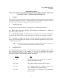
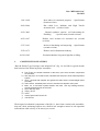
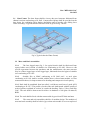
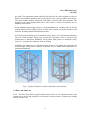
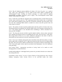
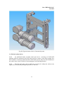
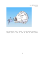
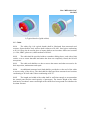
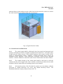
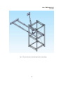
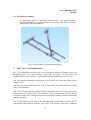
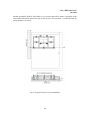
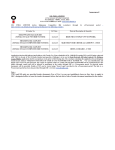
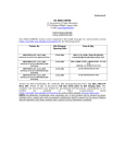
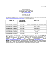
Doc: MED 18(1131)C
Oct 2012
Draft for Comments Only
Draft Indian Standard
RACK AND PINION TYPE PASSENGER CUM MATERIAL LIFTS – USED FOR
CONSTRUCTION – GENERAL REQUIREMENTS
ICS 91.220
_______________________________________________________________________
Not to be reproduced without the permission of
Last date for receipt of
BIS or used as a STANDARD
comments: 15 Nov 2012
_______________________________________________________________________
FOREWORD
Formal adoption clause to be added later on.
Rack & Pinion Type Passenger cum Material Lift, as the name implies, is basically a lift
with rack & pinion arrangement, for vertical transportation of passengers and materials at
the site of construction. No machine room, no lift shaft, no wire ropes and no counter
weights are required in these lifts. As such, much lesser time is required for erection /
commissioning of these lifts. Maintenance cost of these lifts is also low as compared to
the conventional wire rope type lifts. It is very useful for high speed elevation of
workmen, supervisors, engineers, construction materials, tools, tackles etc. for
construction of multi storey buildings and high rise structures. It may be of single cabin
type or of twin cabin type. In twin cabin type lifts, two cabins operate on the same mast
structure.
In view of the increasing use of Rack & Pinion Type Passenger cum Material Lift at
construction projects of multi storey buildings, chimneys and other high rise structures
and also in view of the fact that manufacture of such lifts has already been started in the
country by some of the manufacturers, it is considered necessary to lay down standards
for this equipment. The purpose of this standard is to set forth minimum requirements
intended to provide for the safety of life, limb and property of those engaged in
occupations requiring the use of personnel hoists or employee elevators.
This standard applies to the design, manufacture, installation, operation, inspection,
testing, maintenance, alterations and repair of hoists and elevators that (1) are not an
integral part of buildings, (2) are installed inside or outside buildings or structures during
construction, alteration, demolition or operations and (3) are used to raise and lower
workers and other personnel and material connected with or related to the structure.
For the purpose of deciding whether a particular requirement of this standard is complied
with, the final value, observed or calculated, expressing the result of a test or analysis,
shall be rounded off in accordance with IS 2 : 1960 ‘Rules for rounding of numerical
values (revised)’. The number of significant places retained in the rounded off value
should be the same as that of the specified value in this standard.
1
Doc: MED 18(1131)C
Oct 2012
Draft Indian Standard
RACK AND PINION TYPE PASSENGER CUM MATERIAL LIFTS – USED FOR
CONSTRUCTION – GENERAL REQUIREMENTS
1.
SCOPE
This standard covers construction features, technological requirements and specifications
for design, manufacture, erection / commissioning, operation and safety aspects of Rack
& Pinion Type Passenger cum Material Lift used for construction.
2.
TERMINOLOGY
For the purpose of this standard, the following terms / definitions shall apply:
2.1 Lift: It shall mean “Rack & Pinion Type Passenger cum Material Lift”. It shall not
include any other type of lift.
2.2 Safe Working Load: It shall mean the maximum external load (excluding the
weight of skip unit and cabin), which a lift can safely carry for its continuous operation.
2.3
Capacity: It shall mean the safe working load in MT or suitability of the lift to
safely carry a certain number of passengers for its continuous operation at wind velocity
of 20 metres per second.
NOTE: Actual carrying capacity of the lift shall be ten percent greater than its safe working load
(in MT) or its safe carrying capacity of passengers (in numbers).
2.
REFERENCES
The Indian Standards listed below contain provisions, which through reference in this
text, constitute provisions of this standard. At the time of publication, the editions
indicated against each standard were valid. Since all standards are subject to revision, the
most recent edition of these standards shall be applicable:
IS No.
Title
277: 2003
Galvanized steel sheets (plain and corrugated) –
Specification (fifth revision).
325: 1996
Three phase induction motors (fifth revision).
694: 1990
PVC insulated cables for working voltages up to
and including 1100 V (third revision).
732: 1989
Code of practice for electrical wiring installations
(third revision).
2
Doc: MED 18(1131)C
Oct 2012
1161: 1998
Steel tubes for structural purposes – Specification
(fourth revision).
2062: 2006
Hot rolled Low, Medium and High Tensile
structural steel (sixth revision).
2932: 2003
Enamel, synthetic, exterior: (a) Undercoating (b)
Finishing
– Specification (second revision).
4923: 1997
Hollow steel sections for structural use (second
revision).
5517: 1993
Steels for hardening and tempering – Specification
(second revision).
7078: 1973
Plastics used in Instrument industry.
10234: 1982
3.
Recommendations for general pipeline welding
CONSTRUCTION FEATURES
“Rack & Pinion Type Passenger cum Material Lift” (fig. 1A and 1B for typical sketch)
shall consist of the following major assemblies:
a)
base frame: the lowest framework of the hoist, upon which all other components
are mounted.
b) rack and pinion :a Lift which uses a toothed rack and pinion as the load suspension
system.
c) mast : structure that supports and guides the cabin and the counterweight (when
d)
e)
provided).
mast section: indivisible piece of mast , between two adjacent mast joints
Mast tie: a connection system between the mast and any building structure,
providing lateral support for the mast .
f)
g)
h)
i)
j)
drive and skip unit
Safety device
cabin
control panel and electricals
winch mast
The design of mechanical components of the lift (i.e. base frame, mast & rack assemblies,
skip unit, cabin, anchoring brackets etc.) shall be safe enough to ensure its safe operation
at maximum wind velocity of 20 metres per second.
3
Doc: MED 18(1131)C
Oct 2012
Fig 1A (Typical sketch of rack & pinion type passenger cum material lift -Single Cage)
`
4
Doc: MED 18(1131)C
Oct 2012
`
5
Doc: MED 18(1131)C
Oct 2012
Fig 1B (Typical sketch of rack & pinion type passenger cum material lift -Twin Cage)
6
Doc: MED 18(1131)C
Oct 2012
3.1 Base Frame: The base frame shall be a heavy duty steel structure fabricated from
channel sections conforming to IS 2062. Compression springs shall be provided on the
base frame for cushioning effect during descending and to provide extra lifting force
while ascending. A typical sketch of the base frame is given in fig. 2 below:
Fig 2 (Typical sketch of Base Frame)
3.2 Mast and Rack Assemblies:
3.2.1
The four legged mast (fig. 3 for typical sketch) shall be fabricated from
square hollow steel section of suitable size conforming to IS 4923. However with
specific agreement between the purchaser and the manufacturer, the mast structure
may be of three legged type or four legged type, fabricated from steel pipes of suitable
size conforming to IS 1161.
3.2.2
Suitable ISA or ISMC conforming to IS 2062 and / or steel pipes
conforming to IS 1161 shall be welded with the above referred mast module, as cross
structural members, for improvement of its bending and compressive load capacity.
3.2.3 Rack shall be machined from hot rolled / cold drawn steel bars of grade 45C8
conforming to IS 5517. The profile of teeth of the rack shall match with the profile of
teeth of pinion explained in section 3(c) under the heading “Drive (2 Nos.) and Skip
Unit”. The rack shall be heat treated to achieve its hardness of 160 (plus 10 minus 0)
BHN.
3.2.4 The rack shall be fixed with the mast module by precision HT bolts and nuts.
3.2.5
The mast and rack assemblies shall be of modular design. The modules of
mast and rack assembly shall be built in jigs so that each module is an exact replica of
7
Doc: MED 18(1131)C
Oct 2012
the other. The uppermost module shall be with half rack for safety against over-travel.
Ends of each module shall have dove–tail joints for easy erection of the mast structure.
The mast modules shall be fixed with each other by precision HT bolts and nuts. The
length of each mast module shall not be more than 1.6 meters to facilitate ease of
handling and erection.
3.2.6 Standard engineering practices / recommendations for welding (refer IS 10234)
shall be followed for welding of pipes / hollow steel sections for proper fusion of weld
material. Welding shall be uniform and smooth.
3.2.7 Each pinion shall possess a minimum safety factor of 2.0 against the endurance
limit for tooth strength, taking into account the maximum wear as stated in the
manufacturer’s instruction handbook. Each pinion shall possess a minimum safety
factor of 1.4 against the endurance limit for pitting.
3.2.8 The rack shall possess a minimum safety factor of 2.0 against the static limit for
tooth strength, taking into account the maximum wear as stated in the manufacturer’s
instruction handbook.
Fig. 3 (Typical sketch of a module of Mast & rack assembly)
3.3 Drive and Skip Unit
3.3.1 The drive (fig. 4B for typical sketch) shall consist of AC induction motors with
reduction gear boxes and pinions for conversion of rotary motion of pinions into sliding
motion over the rack.
8
Doc: MED 18(1131)C
Oct 2012
3.3.2 The AC induction motors shall be of 3 phase, 415 volts, 50 cycles / sec., squirrel
cage, TEFC type conforming to IS 325. Each electric motor shall be equipped with
electromagnetic brake working on FAILS principle i.e. brake shall be applied
automatically on failure of electric power supply. The electromagnetic brakes shall
operate with suitable DC supply.
3.3.3 Each drive unit shall be equipped with a centrifugal brake, mounted between the
electric motor and the gear box. The centrifugal brake shall operate due to centrifugal
force when the descending speed of the lift exceeds the maximum specified speed on its
free fall. The centrifugal brake shall be suitable for release when the speed of the lift
comes back to normal.
3.3.4 The profile of teeth of pinions shall match with the profile of teeth of the rack.
The pinions shall be machined from 40Ni6Cr4Mo3 alloy steel forgings conforming to IS
5517. The pinions shall be case hardened after machining to achieve hardness level
between 180-230 BHN.
3.3.5 The skip unit (fig.4A & 4B for typical details) shall be a heavy duty structural
steel assembly having provision for mounting the drive unit, Fail safe device and cabin.
The design shall be such so as to ensure minimum vibrations to the cabin. It shall be
fabricated from structural steel sections conforming to IS 2062.
3.3.6 Four sets of double nylon guide roller assemblies and sufficient number of single
nylon guide roller assemblies (fig. 5) shall be mounted on the skip unit for sliding along
the mast. The nylon rollers shall be machined from cast plastic material conforming to IS
7078. The nylon guide rollers shall be provided with maintenance free life lubricated
sealed bearings.
3.3.7 Safety Hook : Appropriate provision of safety hook to be made to avoid
disengagement of cabin from mast.
3.3.8 Cenrifugal Brake: Centrifugal brake system to be provided with drives to reduce the
free fall speed of lift
3.3.9 Brake release device: In case of power failure to bring down the lift to nearest
landing emergency brake release device to be provided inside the cabin.
9
Doc: MED 18(1131)C
Oct 2012
Fig 4A (Typical sketch of skip frame with safety hook)
10
Doc: MED 18(1131)C
Oct 2012
Fig 4B (Typical sketch of Drive Unit and skip unit)
3.4 Fail safe safety device
3.4.1
An additional brake assembly (Fail safe device ) working on FAILSAFE
principle shall be mounted on the skip unit (fig.4B) to ensure extra safety against free
fall. It shall be a totally mechanical brake which shall operate under free fall condition of
the cabin; in the event of failure of electromagnetic and centrifugal brakes.
3.4.2
The Fail safe safety device shall have provision for taking the cabin to the
upper floor mechanically through its pinion over the rack.
11
Doc: MED 18(1131)C
Oct 2012
3.4.3 The method for release of the safety device shall require the intervention of a
competent person in order to return the hoist to normal operation.
12
Doc: MED 18(1131)C
Oct 2012
Fig
5 (Typical sketch of guide rollers)
3.5 Cabin
3.5.1
The cabin (fig 6 for typical sketch) shall be fabricated from structural steel
sections. Square hollow steel sections shall conform to IS 4923. Steel pipes conforming
to IS 1161 may also be used in place of square hollow steel sections. Other steel sections
(i.e. ISA, ISMC, plates etc.) shall conform to IS 2062.
3.5.2
The cabin shall be provided with two numbers sliding doors, each with a limit
switch, so as to ensure that until and unless the doors are completely closed, the lift will
not operate.
3.5.3
The cabin roof shall have a door to assess the motors and other accessories for
their inspection, maintenance and repair.
3.5.4
An additional structural steel shed shall be provided over the roof of the cabin
to ensure safety of the drives. The shed shall be fabricated from structural steel sections
conforming to IS 2062 and GI sheet conforming to IS 277.
3.5.5
The length and width of the cabin shall be sufficient enough to accommodate
the control panel and the rated capacity of passengers. The interior height of the cabin
shall not be less than 2 metres and height of the cabin floor from ground level shall not be
less than 500 mm.
13
Doc: MED 18(1131)C
Oct 2012
3.5.6
The cabin shall be of heavy duty design to ensure minimum vibrations during
its ascending and descending movements.
3.5.7 Any clearances around the edges of each gate or between gate sections shall
conform to EN 294:1992, Table 4 except for under the gate where the clearance shall not
exceed 35 mm.
The safety distance between the landing side of the top of the gate and any travelling part
of the hoist in normal operation shall not be less than 0.85 m, if the rated speed exceeds
0.7 m/s or 0.5 m if the rated speed is not more than 0.7 m/s. The safety distance between
the hoistway side of the top of the gate and any travelling part of the hoist in normal
operation shall not be less than 0.75 m, if the rated speed exceeds 0.7 m/s or 0.4 m if the
rated speed is not more than 0.7 m/s.
3.5.8 General requirement:
The cabin shall take the form of a fully enclosed cage. For prescribing the maximum
number of persons permitted in the cage, a cabin floor area of 0.2 m² per person shall be
used; each person shall be considered to weigh 80 kg. The cabin structure shall be
calculated according to 5.2. The cabin shall have rigid guiding to prevent disengagement
or jamming. The cabin shall be provided with effective devices which retain the cabin to
the cabin guides in the event of the normal guide shoes or rollers failing. The cabin shall
be provided with mechanical means to prevent it from running off the guides. These
means shall be in work as well during normal operation as during erection, dismantling
and maintenance. The cabin shall be provided with effective means to both detect an
14
Doc: MED 18(1131)C
Oct 2012
unsecured mast section and prevent the cabin from driving onto this section or to ensure
the cabin cannot become detached from the secured mast
Fig. 6 (Typical sketch of cabin)
3.6 Control Panel And Electricals
3.6.1
The control panel shall be fabricated from sheet metal and structural steel
sections conforming to IS 2062. It shall be mounted on the cabin floor / wall of the cabin.
It shall house all control circuits, VFD (variable frequency drive) panel, rectifier for DC
supply to electromagnetic brakes, voltmeter, overload protection relays, buzzer for
mechanical brake operation, visual indications, emergency switch and all operating
switches / controls with direct connection to the electric motors and to the limit switches.
3.6.2
The compact design of the control panel shall be such that it is directly
connected to the power supply cable of the customer. It shall be provided with an earth
terminal for direct connection to the earthing system of the customer.
3.6.3
All electrical works of the lift shall be carried out in accordance with the
provisions of “Indian Electricity Act, 1910” and “Indian Electricity Rules”. The
installation shall also comply with provisions of IS 732.
15
Doc: MED 18(1131)C
Oct 2012
3.6.4
All cables and wiring of the lift installation shall be of suitable grade. No
bare conductor shall be used in the lift.
3.6.5
The cabin shall be provided with adequate illumination. At least one socket
outlet, suitable for hand lamp or hand tools, shall be provided in the cabin.
3.6.6
The flexible cable shall be of copper conductor conforming to IS 694.
Suitable reeling arrangement (i.e. cable holding brackets and cable drum) of proven
design shall be used.
3.6.7
Limit switches of proven quality shall be used for safety of the lift. A basic
lift shall be equipped with minimum seven numbers limit switches (i.e. 2 Nos. for upper
limit, 2 Nos. for lower limit, 1 No. for roof door and 2 Nos. for cabin sliding doors).
3.6.8
Variable Frequency Drive (VFD) of proven quality shall be used. The VFD
shall ensure 0-50 Hz frequency and 50-0 Hz frequency to ensure jerk free and smooth
operation of the lift during its upward travel, stop and downward travel operations.
3.6.9
The basic lift shall have push buttons for UP-START and DOWN-START
operations with AUTO mode facility for travel up-to top and ground floor through relay
logic control circuit. The operator shall have to push the required push button and hold it
until the destination floor has reached.
3.6.10
With a specific mutual agreement, the manufacturer may agree for providing
AUTO stop / start facility at desired floors through PLC circuit. The manufacturer shall
provide two numbers “Read Switches” (Sensing Switches) of proven performance for
each floor where auto start / stop facility is desired by the purchaser.
3.6.11 Any one of the following faults envisaged in the electric equipment of a hoist shall
not, on its own, be the cause of dangerous malfunction of the hoist. Faults envisaged:
a) absence and loss of voltage;
b) voltage drop of at least 20%;
c) insulation fault in relation to the metalwork or the earth;
d) short circuit or open circuit, change of value or function in an electrical component
such as for instance resistor, capacitor, transistor, lamp;
e) non attraction or incomplete attraction of the moving armature of a contactor or relay;
f) non separation of the moving armature of a contactor or relay;
g) non-opening of a contact;
h) non-closing of a contact;
16
Doc: MED 18(1131)C
Oct 2012
3.7 Anchoring Bracket Assemblies
3.7.1
The anchoring bracket assemblies (fig. 7 for typical sketch) shall be fabricated
from structural steel sections and / or pipes / hollow square steel sections conforming to
IS 2062 and / or IS 1161 / IS 4923 respectively.
3.7.2
The anchoring brackets shall be of heavy duty design to ensure sturdy support to
the mast against tilting, for operation of the lift at its rated speed and wind velocity of 20
metres / second.
3.7.3
The design of the mast modules shall be such that no anchoring is required for
its free standing height up-to 6 metres.
3.7.4 The member on whom anchoring brackets fixed should strong enough to sustain
the load specified by manufacturer.
17
Doc: MED 18(1131)C
Oct 2012
Fig. 7 (Typical sketch of anchoring bracket assembly)
18
Doc: MED 18(1131)C
Oct 2012
3.8 Winch Mast Assembly
An electrically operated winch mast assembly (fig. 8 for typical sketch) of
suitable rating shall be mounted on the roof top of the cabin for easy erection /
disassembly of the mast modules.
Fig. 8 (Typical sketch of winch mast assembly)
4.
ERECTION / COMMISSIONING
4.1 The manufacturer shall provide a civil foundation drawing, including capacity of
foundation strata to be made available instructions for fixing the base frame and
foundation bolts, to the customer. A typical sketch of the foundation is given in fig. 9.
4.2 The customer shall ensure preparation of firm ground, free from loose earth, before
casting of PCC.
4.3 Erection of mast shall start after a gap of minimum 7 days from the date of casting
of the civil foundation.
4.4 5 Nos. of mast and rack modules shall be assembled and erected on the base frame
with the help of an external crane. The assembly of skip unit and cabin shall be made on
it with the outside crane. Additional mast and rack modules shall be erected with the help
of winch assembly.
4.5 For lift height above 6 meters, the first anchoring bracket shall be fixed to the 3rd
mast module and anchored with the wall of the civil structure. Thereafter, anchoring
19
Doc: MED 18(1131)C
Oct 2012
bracket assemblies shall be fixed after every 3 meters intervals to ensure verticality of the
mast within allowable limit of 50 mm in 100 meters. The last mast is with half rack for
safety against over-travel.
Fig. 9 (Typical sketch of civil foundation)
20
Doc: MED 18(1131)C
Oct 2012
5. PROOF TESTING
5.1 After completion of erection, the performance of the lift shall be tested at a test load
of ten percent greater than its rated capacity (i.e. safe working load). Maximum duration
of this test shall be ten minutes. The lift shall perform satisfactorily for up and down
travels during this test, under normal supply voltage.
NOTE: The above test is performed as a safeguard to cover variations in electric supply
voltage / frequency and atmospheric conditions. The lift is designed to operate with rated
load at specified duty cycle. It shall not be used to carry overloads.
5.2 The lift shall also be tested for five minutes at static overload of 25 % greater than its
safe working load to ensure that brakes sustain the cabin at this overload.
NOTE: The lift shall not be operated for up and down travels during the above static
overload test.
5.3 The lift shall be run continuously for one hour for it’s UP and DOWN operations at
normal electric supply conditions (i.e. supply voltage and frequency) on safe working
load. The electric motors, brakes, control equipment, limit switches, emergency switches
and safety devices shall perform satisfactorily during this test.
6. SAFETY REQUIREMENTS
6.1 Hand railings shall be provided at the roof of the cabin to ensure safety of workmen
during maintenance / repair of the lift.
6.2 A wire-mesh barricade or some suitable steel fencing shall be provided around the
base frame / civil foundation and cable drum to prevent entry of anybody around the lift
area.
6.3 Provision shall be made to ensure that the lift does not start when the cabin is
overloaded. The lift operation shall resume only upon removal of the overload.
6.4 The lift shall be provided with an emergency signal system, which shall be operative
from the cabin and audible outside the lift.
6.5 A suitable intercom facility shall be provided for communication between the
operator and the lift supervisor.
21
Doc: MED 18(1131)C
Oct 2012
7. PAINTING
7.1 All parts and components of the lift shall be provided with two coats each of anticorrosive primer and synthetic enamel paint or PVC paint. Each coat of primer / paint
shall be of 30 micron thickness.
7.2 The components shall be thoroughly cleaned for removal of rust, oil, grease, dust etc.
before application of primer coat. Synthetic enamel paints shall conform to IS 2932.
7.3 Touch up painting shall be done after completion of erection and commissioning for
rectification of damaged paint.
8. MARKING
8.1 Each lift shall have a rating plate, fixed in the cabin, marked with the following
information:
a)
Manufacturer’s name, address and recognized trade mark.
b)
Month and year of manufacture.
c)
Lift Sr. No.
d)
Capacity of the lift.
e)
Maximum permissible wind velocity during erection / during operation.
f)
Maximum permissible height of the mast .
g)
Rating of drive motors i.e. HP / KW.
h)
Make and Sr. Nos. of drive motors and gear boxes.
8.2 Following instructions printed on a metallic plate shall be displayed on the cabin:
a) Safety before use of the lift.
b) Safety during use of the lift.
c) Safety after use of the lift.
d) Operating instructions of the lift.
9. TOOLS AND INSTRUCTION MANUALS
9.1 A tool box shall be provided, with inventory of tools, along-with each lift. It shall
contain the necessary tools for normal running adjustments and lubrication of the
machine.
9.2 One copy each of the following manuals shall be supplied with each lift:
a)
Operation and maintenance manual with lubrication schedules, instructions
for routine / preventive maintenance and trouble shooting.
b)
Spare parts manual.
10. OPERATOR AND MAINTENANCE
22
Doc: MED 18(1131)C
Oct 2012
Before the lift is handed over user should appoint the trained and certified operator
trained by the competent person for operation of lift. Periodic maintenance daily, weekly,
monthly, and annually to be carried out as mentioned in user manual. Worn out part of
the lift to replaced as per the usage and period given by manufacturer.
23
ANNEX
FORMAT FOR SENDING COMMENTS ON BIS DOCUMENTS
(Please use A4 size sheet of paper only and type within fields indicated. Comments
on each clauses/sub-clauses/table/fig. etc be started on a fresh box. Information in
Column 4 should include reasons for the comments and suggestions for modified
wording of the clauses when the existing text is found not acceptable. Adherence to
this format facilitates Secretariat’s work)
Doc. No.: ______________ TITLE: ________________________________________
LAST DATE OF COMMENTS: ____________
NAME OF THE COMMENTATOR/ORGANIZATION: _________________________
Sl.
No.
Clause/Subclause/
para/table/fig.
No. commented
Commentator/
Organization/
Abbreviation
Type of Comments
(General/Editorial/
Technical)
Justification
Proposed
change