1
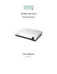
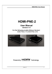
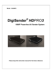
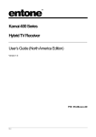
STARTER KIT
USER’S MANUAL ///
INTRODUCTION TO YOUR
HOME MONITORING STARTER KIT ///
FIRST TIME SETUP ///
Thank you for your purchase of the Home Monitoring Starter Kit. The XG1000 Controller, a small
dedicated computer, allows you to access and control cameras and other devices in your home,
and make this information available to you wherever you are. You can access the XG1000 from any
PC (must be running Windows XP or 2000) with an internet connection anywhere in the world.
You can even use the XG1000 from your cell phone. You only need to use a PC to set up your XG1000.
From then on, no PC is required for the XG1000 to function.
PREPARATION:
The system uses IP cameras. These are devices that communicate through normal internet cabling.
If you do not wish to run new Ethernet wiring in your home, you can use Power Line Communication
modules (PLC’s) to use the existing power outlets in your home, instead.
YOUR STARTER KIT CONTAINS THE FOLLOWING ITEMS:
■ XG1000 Controller [X1] with AC Power Supply [A1] and Ethernet Cable [E1]
■ IPC-1000 IP Camera [C1] with AC Power Supply [A2]
■ Door Window Contact Sensor [D1] with Batteries [B1]
■ Controller Mounting Hardware - 2 Feet [F1] & 2 Wall Brackets [G1]
■ Documentation
In addition to the cameras, you can also use sensor modules in your home to monitor temperature,
detect a door or window opening, wet conditions and motion. These are battery powered devices
that communicate wirelessly with the controller. You can even turn lights and appliances on and off,
by purchasing optional power controllers.
WITH YOUR HOME MONITORING ACCOUNT YOU CAN:
■ View Live Video
■ Check Device Status
■ Arm and Disarm Devices
■ Set Up Rules to Perform Actions Based on
Events or Time of Day
■ Record Snapshots and Video Clips
■ Review Archived Events
If you have a JAVA enabled cell phone, you can access most
of the controller functions remotely through the phone.
You need to download an application to your phone
to do this. Other cell phones can receive text notifications,
but cannot view live video or control devices.
XG1000
CONTROLLER
[X1]
IPC-1000
IP CAMERA
[C1]
DOOR/WINDOW
CONTACT SENSOR
[D1]
ETHERNET
CABLE
[E1]
XG1000 AC
POWER SUPPLY
[A1]
IPC-1000 AC
POWER SUPPLY
[A2]
CONTACT SENSOR
BATTERIES
[B1]
MOUNTING
FEET/BRACKETS
[F1 & G1]
Please check the contents of your starter kit prior to starting installation. In addition to
the items supplied in the kit you will also need a DSL/Cable Modem or other high speed
internet connection, a router - or home network device - with at least two unused ports,
and a Windows XP or 2000 PC to set up the XG1000 Controller.
The PC you will be using to install the system needs to be on the same router or local network
as the XG1000 Controller. After the installation, you can access the system from any PC connected
to the Internet.
Your Internet connection and router should be functional before proceeding with this installation.
As part of the purchase, you will have set up a Home Monitoring Account; you will need the
UserID and Password that you created for this account later in the setup procedure.
I
2
HARDWARE INSTALLATION:
FOLLOW THE STEPS BELOW SET UP YOUR HOME MONITORING STARTER KIT:
1. Take the XG1000 Controller AC Power Supply [A1] from your Controller box.
Plug the small end into the port marked Power on your XG1000 Controller [X1]
and plug the other end into an AC electrical outlet.
4. Plug the small end of the AC Power Supply [A2] into your IPC-1000 IP Camera [C1]
AC Adapter port and the other end into an AC electrical outlet.
C1
A2
X1
A1
Example of completed configurations can be found below.
2. Connect supplied Ethernet Cable [E1] to the LAN Ethernet port of the XG1000 Controller [X1]
and connect the other end to a free Ethernet port on your router.
A2
A1
E1
1
3
2
4
LAN
X1
IPC-1000 IP CAMERA
C1
E3
E1
WAN
1
3
2
4
INTERNET
ROUTER
LAN
3. Connect one end of the Ethernet Cable [E1] to the LAN port of the IPC-1000 IP Camera [C1].
Connect the other end to a second free port on your router.
XG1OOO CONTROLLER
X1
WAN
ROUTER
(NOT INCLUDED)
LAN
DSL/CABLE MODEM
(NOT INCLUDED)
COMPLETED CONFIGURATION
NOTE: You can also connect cameras located in any room with an electrical outlet to your
router via optional HomePlug Turbo PLC Ethernet Adapters (sold separately).
PLC
ETHERNET
ADAPTER
C1
VIDEO TRANSMITTED OVER
POWER LINES VIA PLC ETHERNET ADAPTERS
E2
1
1
3
2
LAN
3
2
4
INTERNET
4
LAN
WAN
XG1OOO
CONTROLLER
ROUTER
WAN
ROUTER
(NOT INCLUDED)
LAN
DSL/CABLE MODEM
(NOT INCLUDED)
COMPLETED CONFIGURATION USING OPTIONAL PLC ETHERNET ADAPTERS (SOLD SEPARATELY)
3
4
IPC-1000
IP CAMERA
PLC
ETHERNET
ADAPTER
CONTROLLER REGISTRATION:
1. When you purchased your Home Monitoring system, you created a remote account
with a UserID and Password. Using a web browser on a PC connected to the same
local network as your XG1000 Controller, go to site http://xanboo.com/ss and log in
using this ID and password.
2. After successfully logging in, select the Account Settings tab and then select Discovery.
4. When the controller registration has completed, you will see a confirmation message as
in the following picture. After you successfully register your controller you may be prompted to
follow instructions in order to improve performance.
5. After the controller has been successfully installed and registered, it will automatically start
device discovery. If you don’t see a message that discovery is initializing or in progress, press
the ‘START DISCOVERY’ button. Any cameras that are detected will be registered automatically.
Any other wireless devices need to be registered one at a time. You can do this now or you can
register the additional devices later. To do this, examine the documentation that came with the
device and locate the discovery button on the device. It is usually in a small hole in the case.
Wait until one device is finished registering before you press the discovery button on the next device.
When you are done, press the ‘STOP DISCOVERY’ button.
6. Select the Device Overview tab and verify that all of your devices are shown.
DEVICE DISCOVERY ///
CONTROLLER REGISTRATION
3. To register your controller with the remote service site, press the ‘NEW LOCATION’ button.
A plug-in will be downloaded from http://xanboo.com/ss that enables the browser to
detect and communicate with the controller. A pop-up will be shown that will guide you through
the process. If the software detects any problems with downloading or running the plug-in,
an error message will be displayed that will link to help information. The most common cause
for problems is security settings in the web browser that do not allow the required operations.
YOU CAN ADD DEVICES ANY TIME BY USING THE FOLLOWING PROCEDURE:
1. Select the Account Settings tab and then select Discovery.
2. Press the ‘START DISCOVERY’ button and wait until you get a message indicating
discovery is in progress.
3. Cameras should be detected and registered automatically. If you receive a message
that the camera needs to be reset, press the Factory Defaults button on the camera.
4. For wireless devices, press the Discover button on each device, one at a time
and wait until the device is registered before proceeding to the next one.
5. When you are finished adding devices, press the ‘STOP DISCOVERY’ button.
Go to the Device Overview page and make sure that all of the devices appear in the list
YOU CAN ALSO DELETE DEVICES AT ANY TIME:
1. Select the Account Settings tab and then select Discovery.
2. Press the ‘DELETE’ button next to the device that you would like to remove.
3. Confirm that you want the device to be deleted.
4. Go to the Device Overview tab and confirm that the device no longer appears in the device list.
5
6
USING THE SYSTEM WITH A CORPORATE FIREWALL ///
LIVE VIDEO ///
If you are using the Home Monitoring system in an environment that is protected by a corporate
firewall, you may need to make some settings that will allow you to get the best performance out
of your system. The great majority of users will not need to use these settings.
For each discovered camera you will see a Snapshot of the view associated with the camera when
you click on the ‘LIVE VIDEO’ tab. This snapshot image is for identifying the camera; it is not updated
in real time. The snapshot view for each camera can be refreshed by clicking the ‘REFRESH’ button in
the upper right corner of the image. Click on a camera snapshot to view live video from that camera.
Select Account Settings and then Details. In the section labeled ‘HTTP PROXY’ there are fields
for proxy UserID and Password. These settings will enable the live video window to use the most
efficient method to get data from your camera. If you do not know what to enter in these fields,
you need to ask you System Administrator.
TIME ZONES ///
You must set the time zone in your controller so that events are time stamped with the
correct information. This will also ensure that events you have set up to occur at certain times
will perform as expected.
Because you can access the system from anywhere, there is the possibility that the controller is in
a different time zone than where the remote viewing PC or cell phone is located. The default time zone
for the controller is United States EST. If you need to change this, select the Device Overview tab.
In the bar where the controller name is shown, click on the icon next to the controller name. You will
be shown a pop-up where you can set various controller settings. Select a time zone and click ‘Apply’.
The controller will be reset after this change, which may take a minute or so.
FROM THE LIVE VIDEO PAGE YOU WILL BE ABLE TO:
■ Take a Snapshot of the Current Camera
■ Start or Stop a Live Video
■ Arm the Motion Sensor
■ Toggle Between Cameras
■ Record a Video Clip
The first time you access your Live Video you may be prompted with a pop-up window like the
one below, to install a JAVA plug-in (if you’re using Netscape or Firefox) or ActiveX plug-in (if you’re
using Internet Explorer). This plug-in is necessary to view your Live Video. The appearance of the
plug-in installer will differ for the two plug-ins, but in both cases you must click ‘YES’ to accept the
download for the plug-in. Follow the instructions provided in the INSTALLATION WIZARD for the plug-in.
The plug-in will take a few minutes to install.
JAVA INSTALL POP UP WINDOW
ACTIVE X INSTALL POP UP WINDOW
If you’re using Netscape or Firefox, you will also be prompted by a security warning, like the one
displayed below, when you access your Live Video. Answering ‘ALWAYS’ will prevent this pop-up
from being displayed again.
Selecting ‘YES’ will disable the pop up for only that log-in session.
CONTROLLER SETUP POP UP WINDOW
YOUR HOME MONITORING ACCOUNT! ///
Your account is set up into 4 sections: Live Video, Device Overview, Event Archive and Account
Settings. Each section has a specific role, and understanding each role will allow you to maximize
the Home Monitoring experience.
SECURITY WARNING POP UP WINDOW
7
8
OPTIMIZING YOUR VIDEO PERFORMANCE:
To ensure that your video performance is optimized
you can port forward your router. To do so, please
repeat the controller registration process (refer to
the instructions, steps 1-4, found on pages 5 and 6
of this manual) where you will be prompted with
instructions on port forwarding.
XG1000 CONTROLLER ///
INDICATORS:
There are ten indicators on the front of the controller.
POWER INDICATOR
You will be notified during controller registration if
your video performance has already been optimized.
VIDEO INDICATOR
USING THE FEATURES IN THE LIVE VIDEO WINDOW:
NOT USED
LAN LINK
LAN ACTIVITY
REMOTE
DEVICE STATUS
DEVICE ACTIVITY
NOT USED
NOT USED
LIVE VIDEO WINDOW
The Live Video pop-up displays Live Video image along with buttons that will
allow you to start
or stop
the camera.9
You can manually take a snapshot or record a video by clicking the snapshot
and
video
icons, respectively. Once a Video Clip or Snapshot is taken, they are stored in
the Event Archives section of your account.
Each camera has a built in motion sensor. You can set your camera’s motion sensor to detect
motion by using the Arm Motion Sensor checkbox seen below.
You can switch between cameras using the Camera Selection drop-down menu.
9
XG1000 CONTROLLER FRONT PANEL
FROM TOP TO BOTTOM, THE FUNCTIONS ARE:
■ Power Indicator: Will light up Blue when power is applied.
■ Video indicator: Shows when one or more cameras are in use by flashing Green.
■ Not Used
■ LAN Link: Shows proper Ethernet connection between the controller and the router
with a solid Green
■ LAN Activity: Shows network activity between the controller and other devices
by flashing Green
■ Remote: Shows the status of the remote service connection
• Green indicates good communication with the remote site
• Amber indicates that the controller has not been registered with the remote site, yet.
• Red indicates no communication between the controller and the remote site.
■ Device Status: Shows the worst case status of the devices on the “Monitor” page.
If all devices are Green then this LED will show Green. If one or more devices
are Yellow or Red, the LED will light accordingly.
■ Device Activity: Flashes Green to show when the controller is communicating with
one of the wireless devices.
■ Not Used
■ Not Used
I0
BOOT SEQUENCE
When the controller is first powered up, the bottom five LED’s on the front panel go
through a boot-up sequence. The lights start out as Red, go to Amber and then Green.
The process takes about three minutes.
MOBILE OPTION:
If you have a JAVA enabled cell phone you can access the system from just about anywhere.
Just use your phone’s web browser to download and install the application from
http://xanboo.com/ss and enter your Home Monitoring User ID and Password when prompted.
Data rates will apply, so you may want to consider subscribing to a data package.
REAR PANEL:
The rear panel of the controller contains the ports for cable connections. The bottom round port
is for the power. The AC adapter is plugged into this port. The other port is for the network cable.
A standard Ethernet cable is connected between this port and your router.
The antenna on the back panel is used for communication between the controller and
the wireless devices. It should normally be placed in an upright position. If you are having
communication problems with sensors (as indicated on the “Monitor” page) you should try
repositioning the antenna slightly.
If you are unable to access the controller, you may need to reboot the unit. There is a recessed
button on the back labeled ‘REBOOT’. This button will reboot the controller while retaining all of
the internal settings. You can use the white reset tool that comes with each sensor device to
activate this button. The system will go through the normal boot sequence.
ANTENNA
CONTROLLER REBOOT BUTTON
ETHERNET CONNECTOR
POWER CONNECTOR
XG1000 CONTROLLER REAR PANEL
II
I2