1
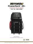
TRANSTECH III
Transmission Service System
Part No. 500-1100P
USER MANUAL
UNIT EQUIPPED WITH V-2 CONTROL BOARD
1324 Blundell Rd. Mississauga ON
Tel. 905.615.8620
Fax. 905.615.9745
www.motorvac.com
Table of Contents
Page
Introduction ...............................………….....…………………………..................................................... 1
Overview ………………............................................………………………………............…….………… 2
System Features and Functions ………..…………………………………………….....................………… 3-4
Front View - Control Panel Features and Functions …..………....….....……............................... 3
Right Side Features ….……………………….……………….………………................................ 4
Left Side Features ...………...…….…………………................................................................... 4
Theory of Operations ….......................……………………………………………...……………………...... 5-6
Safety Information and Precautions……..……………………………………………..…………………....... 6-7
TransTech III Auto-Prime Procedure ………………………....……………………………………................. 8
Transmission Service Procedure ………………………....……………………………………...................... 9-12
Frequently Asked Questions ………………………....…………………………………......…...................... 13
Maintenance Procedures ………………………....…………………………………......….......................... 13
Cleaning the Unit’s Filter ………………………....…………………………………......…............................ 13
Troubleshooting and Additional Help ………………………....………………………………...................... 14
Error Alerts ………………………....…………………………………......…................................................ 15
TransTech System Accessories ………………………....…………………………………......…................. 16-18
Parts ………………………....…………………………………......…........................................................ 19
[email protected]
www.motorvac.com
Introduction
Congratulations on your selection of the TRANSTECH III Transmission Service System. By choosing this
product, you are acquiring the most technologically advanced method available for automatic transmission
service and fluid exchange.
The TRANSTECH III System is a self-contained system; designed to connect to any automatic transmission
through its cooling system lines. Once the unit is connected, it can be used to drain the fluid from the vehicle’s transmission for filter replacement and/or to completely exchange the transmission fluid with new fluid,
without removing the vehicle’s transmission fluid pan.
With the engine idling, the unit will receive the used fluid expelled by the vehicle’s transmission fluid pump
through one of the hoses connected to the transmission cooling system, and supplies new fluid through the
second hose connected to the other side of the disconnected transmission cooling line.
It is recommended that a vehicle’s transmission lubrication system according to the vehicle owner’s manual
to obtain the highest lubricant protection, to reduce friction from internal transmission components, and thus
increase the efficiency and life span of the transmission.
Please study this Operators Manual to become thoroughly familiar with the TRANSTECH III Transmission
Service System.
IMPORTANT
The TRANSTECH III Transmission Service System is designed to work
EXCLUSIVELY with transmission fluid and MotorVac brand chemicals.
Any operational failure through the use of other products (except automatic transmission fluid)
in the TRANSTECH III System voids the manufacturer’s warranty.
See warranty card for details.
1
[email protected]
www.motorvac.com
Overview
This manual contains all the information you need to use the TRANSTECH III system. Please make sure all
technicians using the unit read this manual and have it within easy reach whenever the unit is being used.
The following is a quick reference to the information in this manual:
System Features and Functions
This chapter describes the TRANSTECH III Transmission Service System’s Switches, Lights and
Connections.
Safety Information
Adhere to the safety guidelines in this chapter at all times!
Before You Begin
Follow the instructions in this chapter before using the unit for the first time.
Service Procedure
This chapter contains step-by-step setup and service procedure for using the unit to drain the vehicle’s
transmission oil pan and/or to exchange the fluid completely.
Frequently Asked Questions
Contains helpful information to common questions.
Troubleshooting and Additional Help
Turn to this chapter in the unlikely event you have problems with your TRANSTECH III system or need
additional help.
Appendices - Maintenance, Accessories, and Parts
The appendices contain information regarding cleaning the filter screen, viewing available accessories and
replacement parts.
2
[email protected]
www.motorvac.com
System Features and Functions
The front of the TRANSTECH III cabinet contains the control panel, the fluid fill neck for adding new transmission fluid and the fluid level windows.
A
B
C
G
H
D
E
F
I
J
Front View - Control Panel Features and Functions
A. Start / Resume
(Fluid Exchange)
Begins service - Starts exchanging new fluid for used fluid. NOTE: With DRAIN, FILL, and ENGINE START
light on, service is in progress.
B. Drain
Drains fluid from vehicle’s transmission. When performing filter change, an alarm will sound when the
transmission is empty.
C. Low Vehicle Fluid
lluminates when fluid from the vehicle in service is low or empty.
D. Complete
Illuminates when service is complete or the stop button has been pressed
E. Start Engine
Flashes when the vehicle’s engine needs to be started, Is on solid when the vehicle’s engine is running and
sufficient flow is seen from the transmission.
F. Stop Engine
Flashes when the vehicle’s engine needs to be stopped,
Is on solid when the vehicle’s engine is OFF.
G. Fill (Top Off)
Adds fluid to the transmission.
H. Low Clean Fluid
Illuminates when clean fluid in the unit’s clean tank is empty.
I. Stop
Stops alarm if alarm is sounding.
Pauses the service if alarm is not sounding. Press Change Fluid button to resume service.
J. Empty Waste
Empties used waste fluid from unit’s waste tank.
New Feature: Whenever the TransTech is reset with fluid in the waste tank, the Empty Waste LED will flash.
Note: It is not necessary to empty the Waste Tank before performing an exchange. If beginning an exchange with fluid in the waste tank ensure that there is less fluid in the clean tank than the remaining capacity
of the waste tank. Failure to do so will result in Waste Tank overflowing!
3
[email protected]
www.motorvac.com
System Features and Functions (Cont’d)
C
Right Side Features
A
D
B
A. Output Hose
Connects to the transmission’s cooling system.
B. Quick Coupler
Secures the unit’s output hose connection to the
adapter connected to the vehicle’s transmission
cooling system.
C. Serial Plate
dentifies the unit’s model and specific
manufacturer’s production number.
D. Battery Cables
Positive (red) and negative (black) battery
connections.
D
Left Side Features
A
E
C
B
F
4
A. Adapter Tray
Stores machine’s service adapters.
B. Disposal Hose
Is inserted into the shop’s fluid recycling
container or into a suitable container for proper
disposal of used transmission fluid.
C. Quick Coupler
Secures the unit’s Return hose connection
to the adapter connected to the vehicle’s
transmission‘s cooling system.
D. Fill Neck Cap
Access for filling new transmission fluid into
unit’s clean tank.
E. Return Hose
Connects transmission through its cooling
system.
F. Disposal Hose
Check Valve
Prevents excessive drainage from waste hose,
opens automatically when EMPTY WASTE
button is pushed.
[email protected]
www.motorvac.com
Theory of Operations
Descriptions of the various operations, control buttons, and indicators that make up the control panel are
listed below.
OFF MODE:
• When the unit is connected to power, an alarm will sound indicating power-up, all LED’s will flash on and
off and then the ENGINE START light will be flashing.
• When the vehicle is started, the fluid and pressure from the vehicle should have reached the machine
and the ENGINE START light will go steady on and the gauge will indicate the pressure coming in from
the vehicle. It is now ready to begin a service if there is fluid in the clean fluid tank.
SERVICE MODES:
• Push DRAIN button to perform a drain pan service on vehicle. The unit will automatically route the
used fluid from the vehicle’s transmission into the unit’s waste tank until the transmission is empty and
the pressure drops.
Push CHANGE FLUID button to perform a fluid exchange. The unit will route the used fluid from the
vehicle’s transmission into the unit’s waste tank and supply an equal amount of new fluid from the unit’s
clean tank into the transmission. During the service the ENGINE START lights will be on steady. The
DRAIN and FILL lights may go on and off periodically as the unit controls the fluid level in the vehicle.
DRAIN MODE at the end of service:
• After service is complete, (COMPLETE light is on), if the transmission level needs to be lowered push
the DRAIN button. Fluid will drain only as long as the button is pressed, flow will stop when the button is
released.
FILL (TOP OFF) MODE at the end of service
• Push FILL button after service is complete (or COMPLETE light is on, see step below). Fluid will flow into
the vehicle’s transmission only as long as button is pushed
LOW CLEAN FLUID LIGHT:
• The light will be on when the clean fluid tank is empty down to the zero mark.
COMPLETE LIGHT:
• The COMPLETE light will turn on at end of service. The unit will automatically revert to bypass mode.
ENGINE START LIGHT:
•
The light will flash if the engine needs to be started or if fluid flow needs increased.
•
The light will be on solid when the engine is running indicating good flow from the vehicle.
ENGINE STOP LIGHT:
•
The light will flash if the engine needs to be stopped/turned off.
•
After the engine is stopped/turned off, the light will be on steady.
EMPTY WASTE LIGHT:
• A flashing empty waste LED after an exchange is complete or before one has began indicates that
there is fluid in the waste tank. If the EMPTY WASTE button is pushed at this time the unit will empty
the waste tank to the ‘zero’ line. Note: It is not necessary to empty the Waste Tank before performing an exchange. If beginning an exchange with fluid in the waste tank ensure that there is less fluid in
the clean tank than the remaining capacity of the waste tank. Failure to do so will result in Waste Tank
overflowing!
STOP SWITCH:
• Will turn off an alarm without stopping the machine when an alarm is sounding during the CHANGE
FLUID mode (when pushed only once).
• Will pause the service and revert the system to bypass mode and hold the fluid level memory when
pushed without the alarm sounding. Press the CHANGE FLUID button to resume service.
5
[email protected]
www.motorvac.com
Theory of Operations
SPECIAL CONTROL FEATURES:
PRESS AND HOLD MODES: Press and hold these buttons for five seconds to enable special functions.
RESET MACHINE: press and hold STOP button for 5 seconds will cause a ‘reset’ of the control board. (This
will do the same as disconnecting the power cord).
MANUAL EMPTY WASTE: Press and hold the EMPTY WASTE button for 5 seconds to enable manual
control of the waste pump. The alarm will sound after the 5 seconds, release the switch and the empty
waste light will come on. The waste pump can then be started and stopped by touching the empty waste
switch.
MANUAL DRAIN & FILL: Press and hold the CHANGE FLUID button for 5 seconds. The unit will beep
indicating the machine is in manual mode. The DRAIN & FILL buttons are now active. Press and hold to
activate function. When the button is released, the drain or fill function will stop.
Safety Information and Precautions
/!\ DANGER
1. Vehicle exhaust gases contain Carbon Monoxide, which is a colorless and odorless lethal gas.
2. Only run engines in well-ventilated areas and avoid breathing exhaust gases.
3. Extended breathing of exhaust gases will cause serious injury or death.
/!\ WARNING
1. Exhaust gases, moving parts, hot surfaces are present during and after the vehicle’s engine is running.
2. Read and understand the operator’s manual before using the TRANSTECH Service system.
3. When using petroleum products always refer to the MSDS sheets and manufacturer’s instructions for the
proper procedure to handle emergency medical treatment, cleanup, handling, and storage requirements.
4. Improper use of the TRANSTECH Transmission Service System or exposure to exhaust gases can cause
injury.
5. Spilled transmission fluid on an engine can ignite.
6. Avoid exposure to flames, sparks, hot engine parts, and other ignition sources.
7. Always keep fully charge fire extinguisher nearby. The extinguisher should have a class B rating and be
suitable for gasoline, chemical, and electrical fires.
8. Cleanup any oil spills immediately.
9. Dispose of contaminated cleanup material according to governing environmental laws.
10. Never look directly into the air induction plenum or carburetor throat when the engine is operating.
11. Always verify hose connections to the transmission’s oil cooler lines before starting the vehicle’s engine.
12. Explosion or flame or exposure to flammable liquid and vapors can cause injury.
13. Flammable liquid (transmission fluid) can splash out of reservoir when filling or when unit is being moved.
14. Always keep Reservoir Cap secure except when filling reservoir.
15. Explosion or flame can cause injury.
16. Transmission cooling systems may maintain residual pressure in connection lines to and from transmission and cooler radiator even after the engine has been turned off.
17. Wear safety goggles.
18. Wear chemical resistant gloves when connecting or disconnecting fitting and adapters.
19. Chemicals can cause harmful byproducts - do not add any chemicals to TransTech reservoir tank.
20. Use only approved automatic transmission fluid.
21. Do not swallow or ingest any chemicals.
6
[email protected]
www.motorvac.com
Safety Information and Precautions (Cont’d)
22. Use with adequate ventilation. Avoid breathing vapors.
23. Do not store chemicals in or on the machine (other than automatic transmission fluid).
24. Improper use of transmission fluid can cause injury.
25. Over exposure can have harmful effect on eyes, skin, respiratory system and possible unconsciousness
and asphyxiation.
26. Improperly blocked vehicles can move.
27. Set the parking brake and chock the wheels.
28. Moving vehicles can cause injury.
29. The engine-cooling fan will cycle on and off depending on the coolant temperature and could operate
without the engine running.
30. Wear safety goggles.
31. Always keep objects, clothing, and hands away from the cooling fans and engine parts.
32. Moving engine parts can cause injury.
33. Hot surfaces are present during and after running the engine.
34. Do not contact hot surfaces such as, manifolds, pipes, mufflers, catalytic converters, or radiators and
hoses.
35. Hot surfaces can cause injury.
36. Catalytic converters become extremely hot.
37. Do not park a converter-equipped vehicle over dry grass, leaves, paper, or any other flammable material.
38. Do not touch a catalytic converter until the engine has been off for at least 45 minutes.
39. Catalytic converters can cause burns.
40. Cracked fan blade can become airborne.
41. Examine fan blades for cracks. If found, do not service the vehicle.
42. Flying objects can cause injury.
43. Batteries produce explosive gases and can explode, resulting in injury.
44. Wear safety goggles when working on or near batteries.
45. Use in a well-ventilated area.
46. Keep sparks and flames away from the battery and never lay tools, equipment, or other conductive
objects on the battery.
47. When is connecting to the battery, make sure the unit’s power switch is off. Connect the positive lead of
the unit to the positive lead battery first; connect the negative lead of the unit to a solid ground point as
far from the battery as possible.
48. Keep battery acid away from skin or eyes. In case of eye contact, flush with clean water for 15 minutes
and get medical attention.
7
[email protected]
www.motorvac.com
TransTech III Auto-Prime Procedure
(For first time set-up only)
Set-Up Instructions:
1. Check the output/return hoses, battery connections, and all external components for damage.
2. Fill the CLEAN FLUID tank with approximately 6 quarts (5.7 liters) of new ATF.
3. Connect two compatible adapters to each other, secure tightly. Attach the CLEAN FLUID & INLINE
RETURN hoses together using the connected adapters. Ensure that both hoses have no kinks or visual
damage.
4. Place the waste hose into the clean tank fill neck with the ball valve open.
5. Attach the units’ red (+) battery clip to vehicle’s positive battery terminal; connect the black (-) battery clip
to a solid ground point as far from the battery as possible.
6. Press and hold the CHANGE FLUID button for 5 seconds until the unit sounds the alarm. The FILL and
DRAIN LEDs will flash. Press and hold the CHANGE FLUID button again for 5 seconds until the unit
sounds the alarm. The DRAIN, FILL and COMPLETE LEDs will cycle in a clockwise direction while the
unit is performing the Auto-Prime procedure. The unit will pump fluid from the clean tank to the waste
tank. The unit will then set the waste tank zero level by pumping fluid from the waste tank into the clean
tank
7. Return the hoses to their original location.
8. The initial setup is complete.
8
[email protected]
www.motorvac.com
Transmission Service Procedure
Follow the steps below to connect the unit to the vehicle’s transmission cooler lines.
Make sure the vehicle has at least 1/8 tank of fuel before beginning this process.
IMPORTANT
Do not perform the transmission service if the vehicle’s engine oil or coolant level is low. If
necessary, add motor oil and/or coolant.
Do not perform service if new transmission fluid is below 50 degrees Fahrenheit.
WARNING
Flammable Liquid can squirt out of pressurized lines when connecting or disconnecting.
Verify that engine and machine are both off before connecting or disconnecting cooler
lines or adapters.
Wear safety goggles.
Wear chemical resistant gloves when connecting or disconnecting fittings and adapters.
Wrap a shop towel around pressure fittings and adapters when disconnecting.
Avoid exposure to flames, sparks, hot engine parts, and other ignition sources.
Explosion or flame or exposure to flammable liquid and vapors can cause injury.
Warning! It is not necessary to empty the waste tank before beginning an exchange. If beginning an
exchange with fluid in the waste tank ensure that there is less fluid in the clean tank than the remaining
capacity of the waste tank. Failure to do so will result in waste tank overflowing!
1. Add the correct amount of automatic transmission fluid into the TRANSTECH’S clean tank reservoir.
See chart:
APPROXIMATED FLUSH CHART
4 Cylinder vehicle
10-12 quarts
6 Cylinder vehicle
12-14 quarts
8 Cylinder vehicle
14-16 quarts
NOTE: Quantity of fluid used per vehicle may vary depending on the condition of the fluid in the
transmission being serviced. Trucks and Step Vans may have a larger transmission, therefore may use
more fluid than specified in this chart.
2. Start engine, let run until it reaches operating temperature, turn engine OFF.
9
[email protected]
www.motorvac.com
Transmission Service Procedure (Cont’d)
3. Locate and disconnect the cooler line at the easiest connection point and install adapters:
a) At cooler line connection to radiator. Connection is usually accessible from the top corner of the radiator (could be on either top side).
b) At clamped rubber hose connection to transmission cooler (connections are usually accessible from
the under side of the vehicle (cooler is usually in front of radiator).
c) At cooler line connecting to the transmission.
4. Connect the FLOW DIRECTION INDICATOR LOOP (‘H’ adapter) to the previously attached cooler line
adapters. Verify that the male to male quick disconnect is not installed in the ‘H’ adapter. NOTE: The ball
valve must be in the (CLOSED) position. (The valve handle is at a right angle to flow.) VERIFY THAT THE
‘MALE TO MALE’ NIPPLES ARE REMOVED FROM THE HYDRAULIC COUPLERS! See photo.
Valve Closed
Couplers
“empty”
Part #200-8099 Patent Pending
5. Attach the unit to the vehicle’s battery by connecting the unit’s red battery clip to the positive (+) battery
terminal and connecting the black (-) battery clip to a solid ground point as far from the battery as
possible. The ENGINE START light will be flashing. NOTE: The ENGINE START light must always be
flashing before starting engine.
6. Start the vehicle’s engine. Note the direction of flow of the dirty fluid, (slightly open the valve if necessary)
from the cooler lines (right or left side of the adapter). After determining direction of flow, rotate the valve
handle 90° (OPEN). Transmission flow is now in the closed loop (or bypass mode) and fluid is circulating
from the vehicle, through the ‘H’ adapter, and back to the vehicle.
7. Attach the units hose marked “DIRTY OIL” to the fitting of the “H” adapter that indicated flow from the
vehicle (dirty side). Attach the hose marked “CLEAN OIL” to the side of the adapter that indicated flow to
the vehicle. (Must use male to male liquid adaptor.) Once unit’s lines are connected to the “H” adapter,
(CLOSE) the “H” adapter valve handle. See photo above. The unit is now in bypass mode (fluid flowing
from the vehicle thru the TransTech unit and back to the vehicle) and is ready to begin service.
10
[email protected]
www.motorvac.com
Transmission Service Procedure (Cont’d)
8. With the vehicle’s engine still running, the ENGINE START light should be ON solid. The PRESSURE
GAUGE will be reading the amount of pressure coming from the vehicle. Check the transmission fluid
level. Feel the hoses for heat. Heat in both hoses will verify good bypass flow from vehicle, through the
unit and back to vehicle. Transmission fluid will automatically circulate in bypass mode until service is
begun. Press the CHANGE FLUID button. The ENGINE START light will be on solid, as will the DRAIN
& FILL lights, indicating that the service is in progress. Pressure reading on the gauge may drop slightly
but there should still be pressure reading on the gauge. If the gauge drops to zero when the service is
started you may have the service hoses hooked up backwards.
If no bypass flow is indicated, DO NOT BEGIN SERVICE.
If the ENGINE START light is still flashing after the CHANGE FLUID button is pressed, bypass flow has
not been achieved. VERIFY good bypass flow before beginning service. Be aware of Low Flow Vehicles:
Toyota, Chrysler, Mitsubishi, Ford Explorer and Ford Ranger need to be in neutral, with engine rpm held
at 1800 the entire service. Feel both lines for heat before pressing the CHANGE FLUID button.
Bypass flow must be achieved by performing one or more of the following procedures (a, b, or c). Also,
see troubleshooting section page 24 for additional bypass flow information.
a)
Verify that the vehicle’s parking brake is set, and then place the gear lever in neutral.
b)
Accelerate and hold the vehicle’s engine steady at approximately 1,800 RPM.
c)
Verify that the vehicle’s parking brake is set, press and hold the vehicle’s foot brake firmly
then place the gear lever in drive. (Dodge & Jeep 4 wheel drive.)
d)
If pressure on the gauge drops to zero after beginning the service the clean and dirty hoses
may be installed backwards. Switch hoses & restart.
9. Verify that waste tank is filling and clean tank is emptying. Service should proceed automatically until fluid
level in clean tank reaches zero level.
10. SERVICE COMPLETE light should come on and unit should switch back to ‘bypass’ flow. Check
vehicles dipstick level and adjust if necessary.
If dipstick level is low, hold down FILL button to increase level.
If dipstick level is high, hold down DRAIN button to decrease level.
11. CHANGE FLUID Service is now complete. Turn off vehicle, disconnect adapters and power cord.
Reconnect vehicles cooler lines. Restart vehicle & check for leaks.
12. Move TransTech unit to waste recycle area, Insert waste hose into waste barrel, Connect power cord to
12 volt battery. EMPTY WASTE light should be on. Press EMPTY WASTE button. Waste pump should
run until fluid reaches zero level and then automatically shut off.
NOTE: BOTH TANKS SHOULD BE @ ZERO WHEN THE UNIT IS STORED
11
[email protected]
www.motorvac.com
Transmission Service Procedure (Cont’d)
Optional Transmission Filter Change:Pan Drop Style Service Procedure.
If the vehicle’s transmission pan filter is to be replaced, perform the following steps.
a)
Follow steps 1 thru 7 then press the DRAIN button on the unit’s control panel. Let the
engine run until the unit’s alarm sounds and the LOW VEHICLE FLUID and ENGINE STOP
and ENGINE START lights are flashing. This means that the transmission has emptied most
of the fluid from the transmission’s fluid pan. Stop engine. Press the STOP button once to
cancel alarm. NOTE: Do not disconnect the power cord from the battery or move the
Trans Tech once the service has begun.
CAUTION
Do not let the engine run for more than one minute after the Low Vehicle Fluid light has lit.
Letting the transmission run for an extended period of time without fluid can cause serious
damage to internal components.
b)
Replace or clean the vehicle’s transmission fluid filter and reinstall the transmission’s oil pan
following outside manufacturer’s recommendations.
c)
Press the CHANGE FLUID button. The unit will begin filling the vehicle’s transmission
corresponding to the amount of fluid previously emptied into the unit’s WASTE tank.
d)
When the pan has been refilled the START light will flash and the alarm will sound until the
vehicles engine is started and pressure is registered on the gauge. The pump will be
stopped until the Start light changes to solid. After the START light changes to solid
the DRAIN and FILL lights will be on. The fluid exchange process is then restarted and the
exchange will continue until the level in the clean tank gets to zero.
Continue with the service until all fluid has been exchanged and the unit stops automatically.
The COMPLETE light will come on and unit will beep continuously until STOP is pushed.
e)
Let engine run for one minute, then check the transmission’s fluid level.
If level is low:
a) When the complete light is on, and the low clean fluid light is on: Press and hold the FILL button for 10-15 seconds.
b) Re-check fluid level, repeat step “a)” if necessary.
If level is high:
a) When the complete light is on, and the low clean fluid light is on: press and hold the DRAIN button
for 10-15 seconds.
b) Re-check fluid level, repeat step “a)” if necessary.
13. Stop engine and let cool if necessary.
14. Disconnect hoses from TRANSTECH and connect the vehicle’s cooler lines to their original connection
ports.
15. Start the engine, check cooler lines for leaks, and re-tighten as necessary.
16. Step on the foot brake firmly, then slowly shift the gear lever to Low Gear (first gear) then back to Park.
Do final check of transmission’s fluid level.
17. Empty waste fluid tank.
18. Leave unit standing empty (to the zero mark) unit next service.
NOTE: use of the “H” flow control adapter is optional.
If you choose to hook the TransTech-III directly to the cooler lines and you do not have the clean and dirty
hoses connected properly for the flow direction, then the pressure gauge will drop to zero and the unit will
not let you start the service.
12
[email protected]
www.motorvac.com
Frequently Asked Questions
1. How is the CLEAN FLUID tank completely emptied in order to change fluid type?
The TransTech III clean tank can be completely emptied. First connect the positive battery
cable to a battery’s positive post. Connect the negative battery cable to the battery’s negative
post. Install an adapter into the unit’s clean side hose. Insert the hose with adapter into a suitable container and tip the unit back slightly. Press and hold the CHANGE FLUID button for five
seconds (DRAIN and FILL lights will blink). Control board is now in ‘manual’ mode. Press the
FILL button. The pump will run until you release the FILL button.
2. The TransTech III seems to take longer to perform a service than when it was new.
If it appears that a service now takes longer, replace the in-line filter located in the DIRTY hose
assembly. Check the cleanable screen filter (clean fluid tank) located inside the machine. This is
accessed by removing the screws from the belt-line between the upper cabinet and the lower
cabinet. Remove the fluid tank cap. Then carefully tip the top cabinet toward the front. The cap
is ‘hinged’ at the front. The tank filters are located at the back on the siphon tubes between the
two pumps.
3. How does the TransTech III know how much fluid to put into a vehicle?
It is up to the operator to determine the amount and type of fluid to be used for each
service.
The TransTech III takes the amount of new fluid in the clean tank, flushes it through the transmission, and returns an equal amount of old used fluid in the unit’s waste tank, leaving the
transmission with all new, clean fluid at the same level it started with. Reference the chart on
page 4-3, step 1.
4. What should I do when the machine will not perform a service?
If you are still unable to correct the problem call MotorVac Technical Support at 1-800-8418810 for assistance.
5. Do I have to monitor the TransTech III during a service?
Although the Trans Tech III is designed to free up the operator’s time, it is advisable to remain
within earshot of the unit to monitor any warning beeps, should they occur.
6. On what vehicles can the TransTech III be used?
Any vehicle with transmission cooler lines that will allow the unit to adapt to it. Bear in mind that
the unit is not designed to service large / heavy-duty vehicles such as buses and large trucks
with Allison transmissions, etc. The Industrial TransTech should be used on these larger vehicles. Medium duty trucks, vans & smaller busses may be used with the TransTech III by using
the optional flow control adapter p.n. 200-6100. By controlling the higher flow rate going into
the TransTech the machine is capable of performing the ‘normal’ service procedure. The TransTech III pump will pump about 1 gallon per minute with ATF of 50 degrees or warmer.
7. Does the TransTech III generate pressure that could damage a vehicle in any way?
The Trans Tech III is designed to match the vehicle’s rate of flow and will not harm any vehicle’s
transmission. This unique patented feature is found only on TransTech units.
13
[email protected]
www.motorvac.com
Maintenance Procedures
The following maintenance procedures should be performed on a routine basis:
1. Carefully clean the exterior with a soft cloth to keep the cabinet looking new. Check the cabinet for
dents or impact markings, if found, inspect for damaged components.
2. Check all hoses and wires for cuts or frays.
3. Clean the unit’s filter screens after every 100 services or 6 months, which ever comes first.
Cleaning the Unit’s Filter
1. Disconnect power harness from power source.
2. Remove the eight Phillip head screws from the unit’s back panel. Unsnap the lamp from back panel and
set back panel aside.
3. Locate the bell shaped plastic filter housing, found at the top of each tank. A clear plastic ½” hose runs
from each filter housing to a pump. NOTE: Clean one filter at a time.
4. Remove the lock clip from the bell shaped plastic filter. Hold the bottom half of the filter while rotating the
top half of the filter counter-clockwise until the four lock tabs clear. Then separate the two pieces by lifting up the top half of the filter.
5. Use a fine pick or bent pin to pull screen away from the filter housing. Clean screen.
6. Assemble in reverse order. NOTE: Use caution not to pinch O-ring on reassembly
7. Enter initials, date, and a check mark in the appropriate boxes of the Maintenance Record section of this
user manual.
14
[email protected]
www.motorvac.com
Troubleshooting and Additional Help
Refer to the list below troubleshooting assistance.
Problem
Possible Cause
1. Unit does not power-up. No LED’s are
illuminated
Polarity is reversed on vehicle battery connection.
Check connection to battery for a loose condition.
Circuit breaker may be tripped. (Automatic reset).
Faulty battery
2. Start light does not stop blinking when the
engine is started.
Observe pressure gauge to see if fluid/pressure is
reaching the machine.
CLEAN FLUID and Inlet hose may be reversed.
Vehicle may have to be placed in neutral to achieve
pressure. Vehicle may be of a low pressure design
or have a thermostat
3. Fluid is not going into the Waste tank during
inline service.
If the DRAIN LED is on (indicating unit should be
draining), and there is pressure reading on the
gauge, but no fluid is going into the waste tank
then the solenoid valve is not ‘switched’. Solenoid
requires a good 12 volts. Low battery voltage,
defective power cable or poor wiring connector
between the board and solenoid can cause this
problem.
4. The unit performs poorly.
Verify that the tank filter screen has recently been
cleaned. (Refer to the maintenance log in to view
dates of services performed.)
5. When first connected to a battery, all the unit’s Verify good battery voltage (12.5 volts) and
lights remain on and gives a steady tone.
connection.
Unit will not operate off a booster pack. Connect to
a new fully charged battery and try again.
Check wiring for damage
6. Unit will not start. Light (LED) on below the ‘fill Check for residual pressure on the gauge. Pressure
switch’
in the dirty hose or defective pressure switch or
wiring.
15
[email protected]
www.motorvac.com
Error Alerts
The TransTech III has been designed to stop the service and alert the operator in certain instances if the unit
is not functioning properly. See below for details.
Alert
Notification
Fill Error The alarm sounds.
See
Figure
Below.
The following LEDs
flash: FILL.
Cause
Hardware
Troubleshooting
steps
Recovery
There is a hardware or
software problem that
has caused the unit
to lose track of how
much fluid is in the
Clean Tank.
Empty the Clean ATF
tank on the TransTech
III before attempting
another exchange.
Press STOP button to
silence the buzzer.
Due to the probability
of an overfill condition,
Note: Do not leave oil the unit cannot recover
standing above the 0 from this error.
This alert prevents
line of the clean tank Reset the unit to
the unit from overfillfor extended periods attempt further
ing the transmission if of time. This may
operation.
there is a problem with cause the unit to lose
the fluid level sensing
track of fluid levels.
system.
16
[email protected]
www.motorvac.com
Description
Picture
ID Mark
Vehicles
Deluxe Adapter Kit
200-3101A
Mating Part
Standard Adapter
Kit 200-3100A
11/22/13
In Euro Kit 2003120
TransTech System Accessories
1
060-0450
Hose Clamp 7/8” I.D. max
General Application
060-1000
060-1300
1/4” Male Bump Tube
Most Asian Vehicles
060-1100
060-1400
5/16” Male Bump Tube
Most Asian Vehicles
060-1200
060-1500
3/8” Male Bump Tube
Most Asian Vehicles
060-1300
060-1000
1/4” Open End Hose
Most Asian Vehicles
060-1400
060-1100
5/16” Open End Hose
Most Asian Vehicles
060-1500
060-1200
3/8” Open End Hose
Most Asian Vehicles
060-1700
062-0170
5/16” Flare, 7/16”-24 - Domestic Vehicles
060-1800
062-0180
3/8” Flare, 5/8”-20 - Domestic Vehicles
060-2000
060-2005
GM 7/16" Inverted Flare Male
GM
060-2005
060-2000
GM 7/16" Inverted Flare Female
GM
060-2010
060-2015
GM 1/2" Inverted Flare Male
GM
060-2015
060-2010
GM 1/2" Inverted Flare Female
GM
060-2020
GM 1/2" Hose
GM
060-2025
VW M12
VW
060-2030
VW M12 with o-ring
VW
1
1
1
1
1
1
1
1
1
1
1
1
1
1
2
060-2035
060-2040
Jeep 5/8-18 male
Jeep
060-2040
060-2035
Jeep 5/8-18 female
Jeep
060-2045
060-2050
SAE J512 45 deg flare 5/8 male
060-2050
060-2045
SAE J512 45 deg flare 5/8 female
060-2055
060-2060
Ford SAE J512 45 deg flare female
Ford
060-2060
060-2055
Ford SAE J512 45 deg flare male
Ford
060-2065
061-1550 (open end
hose)
ADAPTER TRANS BMW 14 MM MALE
BMW
060-2070
060-2075
Adapter Trans BMW - M18 x 1.5 M
70
BMW
060-2075
060-2070
Adapter Trans BMW - M18 x 1.5 F
75
BMW
060-2080
Adapter Trans Saab, Citroen, Lancia - M14 x 1.5 M
80
Saab
Citroen
Lancia
060-2090
Adapter Trans Fiat - M12 x 1.75 M
90
Fiat
1
1
1
1
1
1
060-2095
060-2105
Adapter Trans Audi - M22 x 1.5 M
95
Audi
060-2105
060-2095
Adapter Trans Audi - M22 x 1.5 F
105
Audi
1
17
[email protected]
www.motorvac.com
Description
060-2110
NA
Adapter Trans Opel Corsa
Picture
ID Mark
Vehicles
110
Opel Corsa
Deluxe Adapter Kit
200-3101A
Mating Part
Standard Adapter
Kit 200-3100A
11/22/13
In Euro Kit 2003120
TransTech System Accessories
1
1
060-2300
14 mm Female
060-2402
060-2740
14mm x 1.5 Banjo
Euro / Asia Vehicles
060-2600
060-2300
060-2700
16mm x 1.5 Bubble Flare
European Vehicles
Union - M 14mm X 16mm
European Vehicles
2
1
1
1
1
060-2700
060-2740
060-2402
14mm x 1.5 Banjo Bolt
Euro / Asia Vehicles Use with 060-2402
060-2741
060-2740
14mm Washer
Euro / Asia Vehicles
060-2742
060-2740
14mm x 1.5 Cap Nut
Euro / Asia Vehicles
060-3800
061-0605
061-0005 (optional)
#5 SAE Flare - European Vehicles
060-4200
060-1400
5/16” Male Tube with Locking Quick Connect
Dodge / Ford Vehicles
060-4300
060-1500
3/8” Male Tube with Locking Quick Connect
Dodge / Ford Vehicles
061-0008
DODGE DIESEL
ALLISON 540
DODGE DIESEL
ALLISON 540
061-0010
DODGE DIESEL
ALLISON 634
DODGE DIESEL
ALLISON 634
061-0605
062-0140
060-3800
061-1008
1
1
2
1
1
1
1
1
1
1
1
1
#5 SAE x #6 SAE Union - European Vehicles
FLARE COUPLER
# 10 x # 8
ALLISON TRANSMISSIONS
Chrysler V-10 Diesel Use
Volvo XC60 & 70
061-1550
062-2040
1/2” Open End Hose
062-0100
062-2060
062-0110 (old)
5/16” Male Flare-Deep - Ford Vehicles
062-0120
062-1034
062-0130 (old)
3/8” Male Flare-Deep Ford Vehicles
062-0140
061-0605
#6 SAE Flare - European Vehicles
062-0170
060-1700
5/16” Female Flare - x 1/4” MPT
General Application
062-0180
060-1800
3/8” Female Flare - x 1/4” MPT
General Application
062-1034
062-01200
62-0130 (old)
3/8”Female Flare-Deep - Ford Vehicles
062-2000
062-2005
BMW (Jaguar & Mercedes)
12 mm Male O-Ring Type / Flange Style
O’Ring P/N: 080-3602
062-2000
BMW (Jaguar & Mercedes)
12mm Female Receptacle / Flange Type
BMW (Jaguar & Mercedes)
062-2010
062-2015
10mm Male O’Ring Type / Flange Style
O-Ring P/N: 080-3402
BMW (Jaguar & Mercedes)
062-2015
062-2010
10mm Female Receptacle / Flange - Style
BMW (Jaguar & Mercedes)
1
1
1
1
1
1
1
1
BMW (Jaguar & Mercedes)
1
062-2005
1
1
062-2020
BMW 14mm Male
BMW
Chrysler V-10 Diesel Use with 061-1550
Volvo XC60 & 70
062-2040
061-1550
1/2” Male Tube with Locking Quick Connect
062-2060
062-1034
062-0130 (old)
3/8” Male Flare-Deep - Ford Vehicles
1
1
1
18
[email protected]
www.motorvac.com
Mating Part
Description
062-2061
062-2062
Volvo 850 Application, Volvo V-70 All Wheel Drive
Male O-Ring Type / Flange Style
Volvo 850 Application, Volvo V-70 All Wheel Drive
O’Ring P/N: 080-3602
062-2062
062-2061
Volvo 850 Application, Volvo V-70 All Wheel Drive
Female receptacle / Flange Style
Volvo 850 Application, Volvo V-70 All Wheel Drive
062-2064
Volvo ‘S’ Series Application
Male O-Ring Type / Push Lock Style
Volvo ‘S’ Series Application
Volvo 'V' & 'XC'
O'ring:P/N 080-2326
1
062-2063
062-2063
Volvo ‘S’ Series Application
Female Receptacle / Push Lock Style
Volvo ‘S’ Series Application
Volvo 'V' & 'XC'
1
062-2064
062-2065
Picture
ID Mark
Vehicles
Note: The center hole is ¾” ID x 20 thread
pitch.
Note: O’Ring is not included with adapter.
Please remove o’ring from the old filter and
install in the adapter.
ALLISON 1000 or
SATURN with SPIN-ON
TRANSMISSION FILTER
GM '95 and newer
OPEL Insignia
Mercedes
Chrysler 300C with Hemi 5.7 Liter Engine 05+
062-2066
060-1500
062-2050 (old)
3/8” Male Tube with Locking Quick Connect
062-2068A
062-2069
ALLISON 1000 DURAMAX
Female O-Ring Type / Flange Style
062-2069
062-2068A
ALLISON 1000 DURAMAX
Male Receptacle / Flange Type
062-2070
062-2071
Adapter, Fem 2004 F350 Diesel
2004 F350 Diesel
062-2071
062-2070
Adapter, Male 2004 F350 Diesel
Male 2004 F350 Diesel
062-2072
Deluxe Adapter Kit
200-3101A
11/22/13
Standard Adapter
Kit 200-3100A
In Euro Kit 2003120
TransTech System Accessories
1
G.M. (CADILLAC CTS)
1
062-2073
062-2074
MERCEDES BENZ
Mercedes
1
062-2074
062-2073
MERCEDES BENZ
062-2080
NA
ADAPTER TRANS PSA HEAT EXCH SMALL
062-2080
Peugeot and Citoën
062-2085
NA
ADAPTER TRANS CITROEN HT EXCH
85
Citroen XM
062-2090
NA
ADAPTER TRANS PSA HEAT EXCH LGE
062-2090
Peugeot and Citoën
062-2095
062-3000
VAG Male Adapter
062-3000
062-3000
062-2095
VAG Female Adapter
062-2095
062-4301
Ford retaining clip
062-4400
Adapter, Ford quick disconnect ½”
062-4401
FORD 3/8” - ‘double bump’
065-1033
Adapter, Drain hook for oil flush
Mercedes
1
1
080-0592
080-0593
080-0593
MQD X 1/4” FPT
General Application
Coupler, ¼” MQD x ¼” MPT, Zp
General Application
1
1
080-0594
080-0595
MQD X 3/8” FPT
General application
080-0595
080-0594
MQD X 3/8” MPT
General application
High pressure adapter assembly
General application
1
200-6101
19
[email protected]
www.motorvac.com
Appendix C – Parts
Service Parts for the TRANSTECH III Transmission System.
Please refer to the part numbers below when ordering parts.
Part #
010-0027
040-0604
040-0507
010-5500
010-6100
010-6101
010-5004
010-5602
010-1052
011-0003
040-1200
040-2000
040-2200
010-6060
020-8043
200-1604
040-0613
040-0623
050-1000
200-8665
080-0236
080-6009
200-8612
050-1928
200-9001
050-0011
050-1915
200-8906
200-3100A
200-3101A
200-8643
030-0055
Description
Wheel (8 x 1.75)
Cap Nut (½” ID – Push 0n)
Axle Bushing (Black Nylon)
Axle, Rear Wheels (½” x 20.875 lg.)
Swivel caster
Swivel caster with brake lock
Hose bracket
Adapter tray
Bottle for adaptor tray
Adapter Tray Assembly TTIV
Screw 5/8 php x #6 (for adapter box)
Flat washer #6 (for adapter box)
Threaded Standoff (for adapter box)
Reservoir cap
Harness, External Power
Internal Light / LED type
Screw, Phillips, stainless steel 6-32 (Rear panel)
Screw, Allen Head, 8-32 x 5/8 (Control Panel)
Screen filter inline ½ MPT. Pp.
Output/Return hose assembly / Clear - braided (ONE)
Female Quick Disconnect, ¼ m / barb, Brass
Hose Clamp, ( Crimp Style, Steel )
Disposal hose assembly
Filter for “Dirty” hose assembly.(Wix #33097)
Pressure Gauge Assembly (0-160 psi.)
Gauge (Only)
Lens (Only)
Quick Reference Card
Adapter Kit (Standard)
Adapter Kit (Deluxe)
Assembly Check Valve Clean Pump TTIII
Ball Valve 1/4FNPT Brass Chrome Plated
ORDERING PARTS
Parts for the unit may be ordered by calling MotorVac Customer Service at (800) 841-8810 or
(714) 558-4822. Please have your model and serial numbers available.
www.motorvac.com
[email protected]
20
[email protected]
www.motorvac.com
21
[email protected]
www.motorvac.com
ZIM10-00290 Rev5
1324 Blundell Rd. Mississauga ON
Tel. 905.615.8620
Fax. 905.615.9745
www.motorvac.com