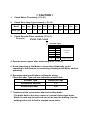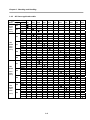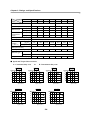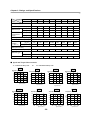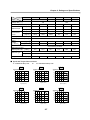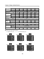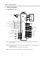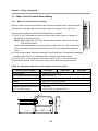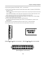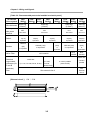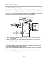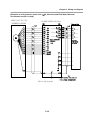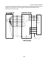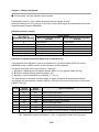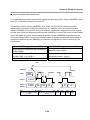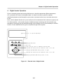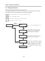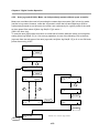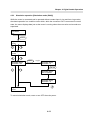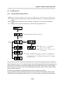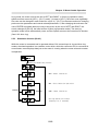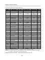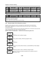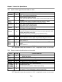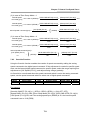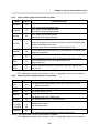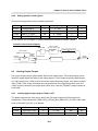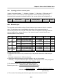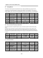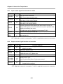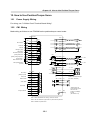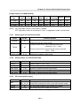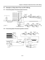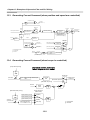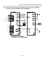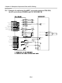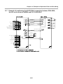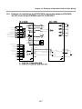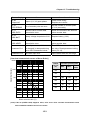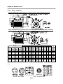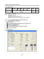
1
OPERATION MANUAL AC Servo Drive FDA5000 Series Ver 3.3 (Soft. Ver. 6.02 ~) FDA5000 Series Servo Drive User Manual < CAUTION > 1. Check Motor ID certainly. ( P1-01 ) 2. Check Drive Amp-Type certainly. ( P1-10 ) 3. Model 5001 5002 5004 5005 5010 5012 5015 5020 5030 5045 5075 Amp Type 0 1 2 5 6 7 11 12 13 14 15 Check Encoder Pulse certainly. ( P1-12 ) Example) FMALN09-AA00 Encoder Type Symbol A B C D E F G Pulse Type 2000 2500 3000 Incremental 5000 15 wires 6000 2048 2048 Absolute 11/13bit 4. Operate servo system after autotuning is off. ( P2-24 ) 5. Avoid impacting to the Motor in connecting. Especially, avoid impacting to the Encoder in connecting coupling to the Motor shaft or operating. 6. Recommended specifications in Encoder wiring. Check Encoder Type and use authorized shield cable. Encoder Type Reference Page Incremental Encoder 3-17 Absolute Encoder 3-20 7. Treatment of the servo motor attached holding brake . : The brake built in the servo motor is a normal closed type brake. Which is used only to hold and can not be used for braking. Use the holding brake only to hold a stopped servo motor. Table of Contents 1. Checking and Handling --------------------------------------------- 1-1 1-1 Handling(Connection of main circuit and motor) --------------------- 1-1 1-2 Caution during Use ---------------------------------------------------------- 1-2 1-3 Installation --------------------------------------------------------------------- 1-3 1-4 Order Specifications --------------------------------------------------------- 1-7 1-5 Functions that facilitate starting ------------------------------------------- 1-10 2. Ratings and Specifications ---------------------------------------- 2-1 2-1 Ratings and Specifications for AC Servo driver FDA-5000 series ------------------------------------------------------------- 2-1 AC Servo Motor Ratings and Specifications -------------------------- 2-2 3. Wiring and Signals --------------------------------------------------- 3-1 2-2 3-1 Representative wiring ------------------------------------------------------ 3-1 3-2 Internal Configuration ------------------------------------------------------ 3-2 3-3 Main Circuit Terminal Board Wiring ------------------------------------- 3-3 3-4 CN1 Wiring and Signal ----------------------------------------------------- 3-9 3-5 Description of CN2 Wiring and Signals -------------------------------- 3-17 4. Digital Loader Operation ------------------------------------------- 4-1 4-1 Displays after power is connected -------------------------------------- 4-3 4-2 Sub-menu Group ------------------------------------------------------------ 4-5 4-3 Operation Monitoring Menu ----------------------------------------------- 4-5 4-4 Changing Parameters ------------------------------------------------------ 4-8 4-5 Test Mode (Test Mode:P6--) ---------------------------------------------- 4-9 5. Mount Loader Operation ------------------------------------------- 5-1 5-1 Initial screen after power is connected --------------------------------- 5-3 5-2 Sub-menu Group ------------------------------------------------------------- 5-4 5-3 Operation Monitoring Menu ------------------------------------------------ 5-5 5-4 Changing Parameters ------------------------------------------------------- 5-9 5-5 Test Mode (P6--) -------------------------------------------------------------- 5-10 6. Parameter Setting ---------------------------------------------------6-1 Parameter Summary -------------------------------------------------------- 6-1 6-2 Table of Contents 6-2 Description of servo status (Status Window: ST--) ------------------ 6-6 6-3 Motor and System Parameters (Motor Parameters: P1--) --------- 6-10 6-4 Common Parameters Related to Control (Control Mode: P2--) -- 6-13 6-5 Speed control parameters (Speed Mode: P3--) ---------------------- 6-21 6-6 Position control parameters (Position Mode: P4--) ------------------ 6-24 6-7 Torque control parameters (Torque Mode: P5--) --------------------- 6-27 6-8 Test Mode parameters (Test Mode: P6--) ------------------------------ 6-28 6-9 Alarm status display (Alarm Status: ALS--) ---------------------------- 6-30 7. How to Use Speed Servo ------------------------------------------ 7-1 7-1 Power Supply Wiring ------------------------------------------------------- 7-1 7-2 CN1 Wiring -------------------------------------------------------------------- 7-1 7-3 CN2 Wiring -------------------------------------------------------------------- 7-3 7-4 Setting Parameters Related to Motor and Servo -------------------- 7-4 7-5 Limiting Output Torque ----------------------------------------------------- 7-6 7-6 Inputting Speed Command ------------------------------------------------ 7-7 7-7 Setting Motor Deceleration/Acceleration Characteristics ---------- 7-10 7-8 Using Monitor ----------------------------------------------------------------- 7-11 7-9 De-resonance Frequency Operation ------------------------------------ 7-13 7-10 Other Set Values ----------------------------------------------------------- 7-13 8. How To Use Position Servo ---------------------------------------- 8-1 8-1 Power Suuply Wiring ------------------------------------------------------- 8-1 8-2 CN1 Wiring -------------------------------------------------------------------- 8-1 8-3 CN2 Wiring -------------------------------------------------------------------- 8-3 8-4 Setting Parameters Related to Motor and Servo -------------------- 8-4 8-5 Limiting Output Torque ----------------------------------------------------- 8-6 8-6 Inputting Position Commands -------------------------------------------- 8-7 8-7 Using Monitor ----------------------------------------------------------------- 8-9 8-8 De-resonance Frequency Operation ------------------------------------ 8-9 9. How To Use Torque Servo ------------------------------------------- 9-1 9-1 Power Supply Wiring ------------------------------------------------------- 9-1 9-2 CN1 Wiring -------------------------------------------------------------------- 9-1 9-3 CN2 Wiring -------------------------------------------------------------------- 9-3 9-4 Setting Parameters Related to Motor and Servo -------------------- 9-4 Table of Contents 9-5 Speed Limiting --------------------------------------------------------------- 9-4 9-6 Inputting Torque Command ----------------------------------------------- 9-5 9-7 Using Monitor ----------------------------------------------------------------- 9-6 9-8 Other Set Values ----------------------------------------------------------- 9-6 10. How to Use Speed/Position Servo ------------------------------ 10-1 10-1 Power Supply Wiring ------------------------------------------------------- 10-1 10-2 CN1 Wiring -------------------------------------------------------------------- 10-1 10-3 CN2 Wiring -------------------------------------------------------------------- 10-3 10-4 How To Use Speed/Position Servo -------------------------------------- 10-4 11. How to Use Speed/Torque Servo -------------------------------- 11-1 11-1 Power Supply Wiring ------------------------------------------------------- 11-1 11-2 CN1 Wiring -------------------------------------------------------------------- 11-1 11-3 CN2 Wiring -------------------------------------------------------------------- 11-3 11-4 How To Use Speed/Torque Servo --------------------------------------- 11-4 12. How to Use Position/Torque Servo ----------------------------- 12-1 12-1 Power Supply Wiring ------------------------------------------------------- 12-1 12-2 CN1 Wiring -------------------------------------------------------------------- 12-1 12-3 CN2 Wiring -------------------------------------------------------------------- 12-4 12-4 How To Use Position/Torque Servo ------------------------------------- 12-4 13. Examples of Operation Flow and PLC Wiring -------------- 13-1 13-1 Generating Speed Command (speed control) ------------------------- 13-1 13-2 Generating Speed Command (position control) ----------------------- 13-1 13-3 Generating Speed Command (position/speed control) -------------- 13-2 13-4 Generating Speed Command (torque control) ------------------------- 13-2 13-5 Example of positioning Unit K7F-POSP connection between FDA-5000, the AC servo driver of HIGEN and PLC MASTER-K ----------- 13-3 13-6 Example of positioning Unit MD71 connection between FDA-5000, the AC servo driver of HIGEN and PLC GOLDSEC-M ------------ 13-4 13-7 Example of positioning Unit G3F-POAA connection between FDA-5000, the AC servo driver of HIGEN and PLC GLOPAPLC -------------- 13-5 13-8 Example of positioning Unit G4F-POPA connection between FDA-5000, the AC servo driver of HIGEN and PLC GLOFAPLC -------------- 13-6 Table of Contents 13-9 Example of positioning Unit G3F-POPA connection between FDA-5000, the AC servo driver of HIGEN, and PLC GLOFAPLC -------------- 14. Maintenance and Inspection -------------------------------------- 13-7 14-1 14-1 Caution ------------------------------------------------------------------------- 14-1 14-2 Inspection Items ------------------------------------------------------------- 14-1 14-3 Replacing Parts -------------------------------------------------------------- 14-2 14-4 Maintenance ------------------------------------------------------------------ 14-3 15. Troubleshooting ------------------------------------------------------ 15-1 15-1 Servo Motor ------------------------------------------------------------------- 15-1 15-2 Servo Driver ------------------------------------------------------------------- 15-2 16. External View ---------------------------------------------------------- 16-1 16-1 External Dimensions of AC Servo Driver ------------------------------ 16-1 16-2 External Dimensions of AC Servo Motor ------------------------------ 16-2 17. Specifications of Options ------------------------------------------ 17-1 17-1 AC servo motor cable specifications ----------------------------------- 17-1 17-2 AC servo driver -------------------------------------------------------------- 17-3 Chapter 1. Checking and Handling 1. Checking and Handling 1.1 Handling (Connection of main circuit and motor) Thank you for purchasing HIGEN AC Servo Driver. Incorrect handling of the driver may lead to unsatisfactory operation or, in some cases, to the rapid reduction of its life, or damage to the servo. Handle and operate the driver according to the instructions given in this manual. * Power Supply : Use power supply within specification (3-phase AC200~230V) (Caution!) If the power voltage is AC 440V,use a transformer to change AC 440V to AC 220V * No Fuse Circuit Breaker or Auto Breaker : Large level of current flows when power is applied to the servo For selection of breakers, refer to Table 3.1, chapter3.3 * Noise Filter : Use noise filters to eliminate external noise that comes with the commercial power supply For selection of noise filters, refer to Table3.1, Chapter3.3 GND * Install magnetic contactors Do not use magnetic contactor to start or stop the servo as it may reduce its life. * Installation place : The operating life of the servo is affected by ambient temperature. Maintain ambient temperature at a level below 50℃ HIGEN * Wiring : Improper wiring may damage to the servo. The control signal line must be sufficiently away from the main circuit wiring so that the line is not affected by noises. * Connection with output terminals : Do not connector condensers ,radios or noise filters during operation as it may cause damage to the equipment. * Grounding : To prevent electric shock and effectively control noise,ground the motor and driver at the shortest distance. (Caution) Use higher than class-3 earth * Motor system : Do not strike the motor shaft and detecter with a hammer. (Caution) Impact may cause damage th the encoder inside the motor 1-1 Chapter 1. Checking and Handling 1.2 Caution during Use Improper handling of the driver may lead to unexpected accident or damage. The following are important points in operating the driver. 1.2.1 Handling y Avoid impact to the encoder, the motor detector. Striking the shaft with a hammer may cause the motor to drop leading to unexpected damage. y Do not connect commercial power supply (AC 220V) directly to the motor. Direct connection induces flow of overcurrent leading to the deterioration of the magnetic effect. Always use specified servo driver. 1.2.2 Wiring y Connect the driver and the motor earth terminals in the direction of the driver, and ground the terminals at the shortest distance in one operation. To prevent electric shock and improper operation, use class-3 earth (Less than 100 Ω). y Always match the U, V ,W and FG terminals of the motor with those of the driver. You cannot change the direction of rotation by changing 2 wires as in the case of widely used common motors. Connecting commercial power supply to the U, V, W and FG terminals of the driver may cause damage. (Apply 200V power supply to R, S and T terminals) Use a transformer in case power supply is other than 200V. Connect standard regenerated resistance to the P and B terminals of the driver. y y 1-2 Chapter 1. Checking and Handling 1.2.3 Operation y Use the magnetic brake of the motor only for emergency and maintenance (preservation). The brake is designed for maintenance (preservation) during power outage. If used to reduce speed, the brake wears out fast. y Install brakes and magnetic contactors on power supply terminals R, S and T. In case an error occurs or abnormal current flows, shut off the circuit to prevent secondary fire. 1.2.4 Maintenance and inspection y "High voltage" still remains inside the driver for a while even after power supply is shut off. (Danger!) To prevent electric-shock, carry out wiring work or inspection at least l0 minutes after the power is cut off and the charge lamp is turned off. y The regenerated resistance and the servo motor remain hot for a while after power is turned off. Touching them may cause burns. y Conducting megger test on the driver may cause damage to the driver. Do not perform megger test. y The motor detector is not detachable. Never remove the cover. 1.3 Installation 1.3.1 y Installation of servo driver Operating environment Ambient temperature 0-50℃ (There should be no freezing) Note) Ambient humidity 90% RH or lower (There should be no steam) Note) Inside panel temperature specifications: To ensure maximum operating life and reliability of the driver, maintain the average panel temperature at 40℃ or lower. If the driver is installed in a place within arm’s reach, install the fan to maintain the temperature of driver at 70℃ or lower. 1-3 Chapter 1. Checking and Handling y Installation direction and intervals - Install the servo driver in such a way that FDA-5000 can be seen from the front. - If the drivers are installed in a closed panel, maintain an interval of more than 10 mm between drivers and more than 40 mm between top and bottom. If multiple number of panels are installed in parallel, about 100 mm space is required on the upper side. Avoid heat by installing fans. - Install heat sources, such as regenerated resistance, away from the driver. y Prevention of ingress of foreign matter - Exercise caution when drilling control panels to prevent chips produced by drilling from getting into the driver. - Take appropriate measures to prevent oils, water and metal powder from getting into the driver from openings in the control panels and the fan installed on the ceiling. - If the driver is used in a place with large amount of toxic gases and dust, protect the driver with an air purge. 1.3.2 y y Servo motor installation Operating environment Ambient temperature 0-40℃ (There should be no freezing) Ambient humidity 80% RH or lower (There should be no steam) External vibration X, Y = 19.6 m/s2 (2G) Caution when assembling load system (Prevent impact on shaft) It is important to accurately match the motor shaft with the shaft center of the connecting machine. Unmatched shaft center causes vibration, and may cause damage to the bearing. Use a rubber hammer to install couplings to prevent excessive force from being applied to the shaft and bearing. Check 4 places in turn. The difference between maximum and minimum should be 0.03 or lower. Load tolerance on shaft - Use flexible couplings, and maintain the shaft center deviations within the specified tolerance. Use pulleys and sprockets that can accomodate the allowable load. - 1-4 Chapter 1. Checking and Handling MOTOR MODEL Series CN KN TN LN KF TF LF y RADIAL LOAD AXIAL LOAD Type N Kgf N kgf CN01~CN05 196 20 68 7 CN06~CN08 245 25 98 10 CN09~CN15 490 50 196 20 CN20~CN30 686 70 343 35 CN30A~CN50A 1470 150 490 50 KN03~KN07 245 25 98 10 KF08~KN11 490 50 196 20 KF15~KN22 686 70 343 35 KN22A~KN55 1470 150 490 50 TN05~TN09 490 50 196 20 TN13~TN17 686 70 343 35 TN20~TN75 1470 150 490 50 LN03~LN06 490 50 196 20 LN09~LN12 686 70 343 35 LN12A~LN40 1470 150 490 50 KF08~KF10 490 50 196 20 KF15 686 70 343 35 KF22~KF50 1470 150 490 50 TF05~TF09 490 50 196 20 TF13 686 70 343 35 TF20~TF44 1470 150 490 50 LF03~LF06 490 50 196 20 LF09 686 70 343 35 LF12~LF30 1470 150 490 50 REFERENCE DIAGRAM Radial Load Axial Load Accuracy of attachments The accuracies of the output shaft and attachments of the AC servo motor are shown on the following table. Item Accuracy (T.I.R.) Perpendicularity of flange attachment plane and output shaft (A) 0.04mm Eccentricity of flange fitting outer diameter (B) 0.04mm Vibration of output shaft end (C) 0.02mm (Note) T.I.R : Total Indicator Reading 1-5 Reference Diagram Chapter 1. Checking and Handling y Impact resistance The driver withstands an acceleration of 10G and two times of impacts when up-and-down impacts are applied after setting the motor shaft horizontally. However, a precision detector is attached to the end of the shaft on the opposite side of the load. Take caution not to apply impact directly to this end. y Vibration resistance The driver withstands a vibration acceleration of 2.0G when vibration is applied in up and down, left and right, and front and back directions after setting the motor shaft horizontally. y Vibration grade The vibration grade of the AC servo motor is V15 at the rated rpm. y Direction of installation - Motor can be installed horizontally or at the top or bottom of the shaft. - Keep the motor cable downward. - If the motor is installed vertically, install a cable trap so that oils or water do not flow into the motor. y Cable disconnection - Take caution not to cause stress or damage to the cables. - If the motor is used as a mobile motor, use movable cables. 1-6 Chapter 1. Checking and Handling 1.4 Order Specifications Prior to installing the product, check the ratings plate to see if the related specifications match with those of the order. 1.4.1 Servo motor model marking FMA ♦ AC Servo Motor ♦ Seal Type Symbol ♦ Series Symbol Use CN,CK High-speed, Low torque type KF,KN Medium-speed, Standard type TF,TN Medium-speed, High torque type LF,LN Item 0 None 1 Oil seal attached ♦ Break Installed Symbol Low-speed, High torque type Item 0 None 1 Oil seal attached 2 130 Flange ( Brake for 24V ) ♦ Shaft Type ♦ Rated Power (Watt) Symbol Symbol Rated Output (W) Symbol Rated Output (W) A Item Straight & No Key 01 100 15 1500 02 200 16 1600 03 300 20 2000 04 400 22 2200 05 450/500 30 3000 Symbol Pulse 06 550/600 35 3500 A 2000 B Straight & Key C Tapper & Key ♦ Encoder Type 07 650 40 4000 B 2500 08 750/800 44 4400 C 3000 09 850/900 50 5000 D 5000 10 1000 55 5500 E 6000 12 1200 75 7500 F 2048 13 1300 G 2048 1.4.2 Type Incremental 15 line Absolute 11/13 bit Servo driver model marking FDA 50 ♦ AC Servo Drive ♦ Encoder Type Symbol ♦ FDA5000 Series None A ♦ Rated Power (Watt) Encoder Type Incremental Absolute ♦ Type Symbol Power (W) Symbol Power (W) Symbol Power (W) Symbol Encoder Type 01 100 10 1000 30 3000 None 02 200 12 1200 45 4500 M Standard type + M/Loader 04 400 15 1500 75 7500 C Position decision type 05 500 20 2000 1-7 Standard type Chapter 1. Checking and Handling 1.4.3 AC Servo application table Drive Motor CK Series 3000 /5000 (r/min) Flange 40 60 60 CN Series 3000 /5000 (r/min) 80 130 180 80 KN Series 2000 /3000 (r/min) 130 180 TN Series 1500 130 /3000 (r/min) 180 Model FDA5001 CKZ5 ◎ CK01 ◎ FDA5004 FDA5005 FDA5010 FDA5012 FDA5015 FDA5020 FDA5030 FDA5045 FDA5075 ◎ CK02 CK04 CN01 CN02 CN03 CN04 CN05 CN04A CN06 CN08 CN10 CN09 CN15 CN22 CN30 CN30A CN50A CN70 KN03 KN05 KN06 KN07 KN06A KN11 KN16 KN22 KN22A KN35 KN55 KN70 TN05 TN09 TN13 TN17 TN20 TN30 TN44 TN55 TN75 FDA5002 ◎ ◎ ◎ ◎ ◎ ◎ ◎ ◎ ◎ ◎ ◎ ◎ ◎ ◎ ◎ ◎ ◎ ◎ ◎ ◎ ◎ ◎ ◎ ◎ ◎ ◎ ◎ ◎ ◎ ◎ ◎ ◎ ◎ ◎ ◎ ◎ 1-8 Chapter 1. Checking and Handling Drive Motor Flange LN Series 1000 130 /2000 (r/min) KF Series 2000 /3000 (r/min) TF Series 1500 /3000 (r/min) LF Series 1000 /2000 (r/min) 180 130 180 130 180 130 180 Model LN03 LN06 LN09 LN12 LN12A LN20 LN30 LN40 KF08 KF10 KF15 KF22 KF35 KF50 TF05 TF09 TF13 TF20 TF30 TF44 LF03 LF06 LF09 LF12 LF20 LF30 FDA5001 FDA5002 FDA5004 ◎ FDA5005 FDA5010 FDA5012 FDA5015 FDA5020 FDA5030 FDA5045 ◎ ◎ ◎ ◎ ◎ ◎ ◎ ◎ ◎ ◎ ◎ ◎ ◎ ◎ ◎ ◎ ◎ ◎ ◎ ◎ ◎ ◎ ◎ ◎ ◎ ◎ 1-9 FDA5075 Chapter 1. Checking and Handling 1.5 Functions that facilitate starting The following are the functions that help diagnosing and starting of the control panel and the machine. Major function Description Autotuning This function automatically calculates the load's inertia moment by detecting the current and speed at the time of starting. Adjusting of the machine, which so far has been carried out based on experience and senses (six senses and intuition), can easily be performed. [Refer to Control Mode, P2-23, 24] Test operation carried out without external instructions (Jog operation) Motor can be run with only the servo driver loader without positioning system or separate operation panel. Motor speed can also be selected freely, and machine operation can be tested easily. [Refer to Test Mode, P6] Motorless operation (Simulation operation) This test mode operation function can operate the servo amplifier without the motor. The control panel can independently check functions or sequences. [Refer to Test Mode, P6] Abundant status display functions With abundant status displays, such as command speed, rpm, load ratio, pulse error and I/O status, the digital servo enables simplified diagnosis of operations. [Refer to Status Window, St--] 1-10 Chapter 2. Ratings and Specifications 2. Ratings and Specifications 2.1 Ratings and specifications for AC servo driver FDA-5000 series Model Item Input power supply Power supply voltage *(Note 1) Power capacity [kVA] Voltage type Continuous output current [A] Maximum output current [A] Detector model Applicable motor Detector Speed command input FDA- FDA- FDA- FDA- FDA5012 5015 5020 5030 5045 FDA5075 3 phase AC200~230V +10/-15%, 50/60Hz 0.5 0.8 1.3 1.5 2.1 2.5 3.1 4.1 6.0 8.0 12.0 3-phase sine wave drive AC servo motor 1.25 2.1 3.2 4.2 6.9 9.8 11 16 21 32 50 3.8 6.3 9.6 12.6 19.2 29 33 48 63 96 132 Standard: Incremental 2000 [p/rev] 15-wire type Not to exceed DC 5 [V], 0.3 [A] 3-phase voltage type PWM drive (IPM used) 1:5000 250 Hz DC -10 ∼ +10 [V], maximum speed (can be adjusted on loader) Internal digital command (operation can be set in 7 steps) Not exceeding ±0.01% (Rated load: 0-100%) Not exceeding ±0.01% (Rated power supply: ±10% ) Position input type Not exceeding ±0.1% (Temperature fluctuation : 25 ±25℃) Can be accelerated/decelerated in straight line or in "S" shape (0-100 [sec] in unit of 0.01 sec) 300 [kpps] Direction + pulse, forward run pulse + reverse run pulse 2-phase pulse (A phase + B phase) Open collector, line driver system Torque command input DC -10 ∼ +10 [V], Maximum command (can be adjusted on loader) Torque linearity Not exceeding 4 [%] Limit speed command Regenerated resistance DC -10 ∼ +10 [V], Maximum speed (can be adjusted on loader) Overcurrent, regenerated overvoltage, overload, motor miswiring, drive overheat, encoder error, voltage shortage, overspeed and excessive error. Standard separately attached type Load inertia (GD²) See motor specifications table Monitor output Speed, torque (-4 ∼ +4 [V]) Dynamic brake built in Testing function (jog and motorless operation), alarm history, forward and backward run, encoder signal frequency division output Power cable, encoder cable, CN1 connector, CN2 connector D/Loader Loader: Mount Loader Digital Loader Acceleration/deceleration time Position input frequency Position input type Protective functions Additional functions Option Environmental specifications FDA5010 Differential line driver output Speed fluctuation rate Built-in functions FDA5005 1000-10000 [p/rev] (Not to exceed 400 [kp/sec]) Speed control range Frequency response characteristics Torque control specifications FDA5004 Detector accuracy Detector power supply Position control specifications FDA5002 Output signal type Drive system Speed control specifications FDA5001 Operating ambient temperature Ambient humidity Not to exceed 90 [%] (Should be free of dewing) Storage temperature -20 ~ +80 [℃] Insulating resistance To be greater than DC 500 [V] 10 [MΩ] Structure Book Type 0-50 [℃] (Note 1) The model name of the servo driver which uses absolute value encoder is FDA-5000A. (Note 2) Single-phase AC 220V can also be used. However, as output may become lower than the rated value, increase the servo driver capacity by 1 step if possible. 2-1 Chapter 2. Ratings and Specifications 2.2 AC Servo Motor Ratings and Specifications Model Spec. Motor CN01 CN02 Driver 5001 5002 CN03 Rated rpm CN06 CN08 5005 CN10 5010 80 (W) 100 200 300 400 500 400 600 800 1000 ( N·m ) 0.32 0.64 0.96 1.27 1.59 1.27 1.91 2.54 3.18 ( kgf·cm ) 3.25 6.5 9.75 13.0 16.2 13.0 19.5 26.0 32.5 ( N·m ) 0.96 1.92 2.88 3.81 4.77 3.81 5.3 6.85 9.53 ( kgf·cm ) 9.75 19.5 29.3 39.0 48.7 39.0 54.5 70.2 97.5 ( r/min ) 3000 Maximum rpm ( r/min ) 2 Rotor ( gf·cm·s ) inertia 2 -4 2 (kg·m ⅹ10 ) ( = GD /4 ) Allowable load inertia Ratio(Versus rotor) Rated power rate ( kW/s ) Detector type CN04A 60 Rated output Maximum instantaneous torque CN05 5004 Flange size ( □ ) Rated torque CN04 5000 0.061 0.095 0.126 0.160 0.204 1.1 1.5 1.77 2.11 0.06 0.093 0.129 0.163 0.208 1.08 1.47 1.74 2.07 Not exceeding 30 times 17.0 43.6 73.9 Not exceeding 20 times 103.5 126.1 15.0 Standard Incremental 2000 Option Absolute 11/13bit 2048P/rev Weight ( kg ) 0.85 1.14 1.43 1.73 2.03 2.1 24.8 37.4 49.0 2.55 3.1 3.7 ■ Speed and Torque Characteristics A : Continuous duty zone CN01 Torque(N·m ) 1.0 1.6 B 0.6 CN03 2.4 B CN04A Torque(N·m ) 4.0 CN06 B 4.4 3.3 1.6 2.2 A 1000 2000 3000 4000 5000 Speed (r/min ) 1.1 2.0 A CN08 5.6 B CN10 8 B 6 4 2.8 A 1.4 1000 2000 3000 4000 5000 Speed (r/min ) 1000 2000 3000 4000 5000 Speed (r/min ) Torque(N·m ) 10 4.2 A A 1.0 1000 2000 3000 4000 5000 Speed (r/min ) Torque(N·m ) 7.0 B B 3.0 0.8 1000 2000 3000 4000 5000 Speed (r/min ) Torque(N·m ) 5.5 2.4 4.0 B 1.6 A 0.6 1000 2000 3000 4000 5000 Speed (r/min ) CN05 Torque(N·m ) 5.0 2.4 1.2 A 0.4 1000 2000 3000 4000 5000 Speed (r/min ) 3.2 B 1.8 0.8 A 0.2 CN04 Torque(N·m ) 4.0 Torque(N·m ) 3.0 1.2 0.4 0.8 B : Intermittent duty zone CN02 Torque(N·m ) 2.0 0.8 3.2 & 1000 2000 3000 4000 5000 Speed (r/min ) 2-2 2 A 1000 2000 3000 4000 5000 Speed (r/min ) Chapter 2. Ratings and Specifications Model Spec. Motor CN09 CN15 CN22 CN30 CN30A CN50A KN03 KN05 KN06 KN07 Driver 5010 5015 5020 5030 5030 5045 5004 5004 5005 5010 Flange size ( □ ) 130 Rated (W) output Rated torque 180 80 900 1500 2200 3000 3000 5000 300 450 550 650 ( N·m ) 2.86 4.77 7.0 9.54 9.54 15.9 1.43 2.15 2.57 3.04 ( kgf·cm ) 29.2 48.7 71.4 97.4 97.4 162.3 14.6 21.9 26.2 31 Maximum instantaneo us torque ( N·m ) 8.6 14.3 21 28.6 23.9 39.8 4.29 6.45 7.42 9.12 ( kgf·cm ) 87.6 146 214 292 243.5 405.8 43.8 65.7 72.7 93 Rated rpm ( r/min ) Maximum rpm ( r/min ) 3000 5000 2 Rotor ( gf·cm·s ) inertia 2 -4 (kg·m ⅹ10 ) ( = GD2/4 ) Allowable load inertia Ratio(Versus rotor) Rated power rate ( kW/s ) Detector type 2000 4500 3000 4.12 7.63 11.12 14.63 26.1 43.8 1.1 1.5 1.77 2.11 4.04 7.48 10.9 14.34 25.6 42.9 1.08 1.47 1.74 2.07 Not exceeding 10 times 20.4 30.6 45.1 63.9 Not exceeding 20 times 35.7 58.9 Standard Incremental 2000 Option Absolute 11/13bit 2048P/rev Weight ( kg ) 5.5 7.0 8.5 10.0 12.9 18.2 18.9 31.3 38.0 44.6 2.1 2.55 3.1 3.7 ■ Speed and Torque Characteristics A : Continuous duty zone CN09 Torque(N·m ) 10 8 B : Intermittent duty zone CN15 CN22 Torque(N·m ) 15 12 B 6 Torque(N·m ) 25 1000 2000 3000 4000 5000 Speed (r/min ) CN50A Torque(N·m ) 10 KN03 Torque(N·m ) 5 B 4 KN05 Torque(N·m ) 6.5 B 5.2 6 3 3.9 4 2 2.6 2 1 1.3 A 1000 2000 3000 4000 5000 Speed (r/min ) A 1000 2000 3000 Speed (r/min ) 4 A 6 1000 2000 3000 4000 5000 Speed (r/min ) KN07 Torque(N·m ) 10 B 4.5 2000 3000 Speed (r/min ) 2-3 8 B 6 3.0 A 1000 1000 2000 3000 4000 5000 Speed (r/min ) KN06 6.0 A 2 1000 2000 3000 4000 5000 Speed (r/min ) Torque(N·m ) 7.5 B B 6 12 A 5 1000 2000 3000 4000 5000 Speed (r/min ) 8 B 18 10 A 3 CN30A Torque(N·m ) 10 24 B 15 6 A 2 CN30 Torque(N·m ) 30 20 B 9 4 8 & 4 A 1.5 1000 2000 3000 Speed (r/min ) 2 A 1000 2000 3000 Speed (r/min ) Chapter 2. Ratings and Specifications Model Spec. Motor KN06A KN11 KN16 KN22 KN22A KN35 KN55 Driver 5005 5010 5015 5020 5020 5030 5045 Flange size ( □ ) 130 Rated output Rated torque Maximum instantaneous torque Rated rpm (W) 600 1100 1600 2200 2200 3500 5500 ( N·m ) 2.86 5.25 7.64 10.5 10.49 16.67 26.18 ( kgf·cm ) 29.2 53.6 77.9 107 107 170 267 ( N·m ) 8.6 14.2 22.5 28.6 26.2 41.7 65.4 ( kgf·cm ) 87.6 145 230 292 267.5 425.0 667.5 ( r/min ) 2000 Maximum rpm ( r/min ) 2 Rotor ( gf·cm·s ) inertia 2 -4 2 (kg·m ⅹ10 ) ( = GD /4 ) Allowable load inertia Ratio(Versus rotor) Rated power rate ( kW/s ) Detector type 180 3000 4.12 7.63 11.12 14.63 26.1 43.8 67.8 4.04 7.48 10.9 14.34 25.6 42.9 66.4 64.7 103.0 18.2 26.8 Not exceeding 10 times 20.4 30.6 53.5 76.7 43.0 Standard Incremental 2000 Option Absolute 11/13bit 2048P/rev Weight ( kg ) 5.5 7.0 8.5 10.0 12.9 ■ Speed and Torque Characteristics A : Continuous duty zone KN06A Torque(N·m ) 10 B : Intermittent duty zone KN11 KN16 Torque(N·m ) 15 B 8 & 6 Torque(N·m ) 25 B 12 20 9 4 A 2 1000 6 3 1000 B 18 12 A 1000 2000 3000 Speed (r/min ) 12 A 5 1000 KN35 2000 3000 Speed (r/min ) KN55 Torque(N·m ) 75 40 60 B 45 B 30 10 15 A 1000 2000 3000 Speed (r/min ) 2-4 A 6 Torque(N·m ) 50 20 6 18 2000 3000 Speed (r/min ) 30 B 24 B 10 A KN22A 24 Torque(N·m ) 30 15 2000 3000 Speed (r/min ) Torque(N·m ) 30 KN22 A 1000 2000 3000 Speed (r/min ) 1000 2000 3000 Speed (r/min ) Chapter 2. Ratings and Specifications Model Spec. Motor TN05 TN09 TN13 TN17 TN20 TN30 TN44 TN75 Driver 5005 5010 5015 5020 5020 5030 5045 5075 Flange size ( □ ) Rated output Rated torque Maximum instantaneous torque Rated rpm 130 180 (W) 450 850 1300 1700 1800 2900 4400 7500 ( N·m ) 2.87 5.41 8.27 10.8 11.5 18.6 27.9 47.7 ( kgf·cm ) 29.3 55.2 84.4 110 117 190 285 486.9 ( N·m ) 8.61 14.2 22.5 29.4 28.7 46.6 69.9 119.3 ( kgf·cm ) 89.5 145 230 300 292.5 475 712.5 1217 ( r/min ) 1500 Maximum rpm ( r/min ) 2 Rotor ( gf·cm·s ) inertia 2 -4 (kg·m ⅹ10 ) ( = GD2/4 ) Allowable load inertia Ratio(Versus rotor) Rated power rate ( kW/s ) Detector type Weight 3000 4.12 7.63 11.12 14.63 26.1 43.8 67.8 126.4 4.04 7.48 10.9 14.34 25.1 42.9 66.4 123.9 80.8 117.4 183.8 26.8 45.7 Not exceeding 10 times 20.5 39.1 62.8 81.1 51.5 Standard Incremental 2000 Option Absolute 11/13bit 2048P/rev ( kg ) 5.5 7.0 8.5 10.0 12.9 18.2 ■ Speed and Torque Characteristics A : Continuous duty zone & TN05 Torque(N·m ) 10 B : Intermittent duty zone TN09 TN13 Torque(N·m ) 15 8 B 6 Torque(N·m ) 25 12 20 B 9 12 6 10 3 5 1000 2000 3000 Speed (r/min ) 1000 TN20 50 24 40 B 18 2000 3000 Speed (r/min ) B 30 6 15 1000 2000 3000 Speed (r/min ) 2-5 2000 3000 Speed (r/min ) TN75 100 10 2000 3000 Speed (r/min ) 1000 60 B 45 A A Torque(N·m ) 125 20 1000 2000 3000 Speed (r/min ) B Torque(N·m ) 75 12 A 6 TN44 Torque(N·m ) 30 A 1000 TN30 Torque(N·m ) 30 24 18 2 A B 15 4 A TN17 Torque(N·m ) 30 75 B 50 A 1000 2000 3000 Speed (r/min ) 25 A 1000 2000 3000 Speed (r/min ) Chapter 2. Ratings and Specifications Model Spec. Motor LN03 LN06 LN09 LN12 LN12A LN20 LN30 LN40 Driver 5004 5005 5010 5012 5012 5020 5030 5045 Flange size ( □ ) Rated output Rated torque Maximum instantaneous torque Rated rpm 130 180 (W) 300 600 900 1200 1200 2000 3000 4000 ( N·m ) 2.86 5.72 8.6 11.5 11.5 19.1 28.6 38.2 ( kgf·cm ) 29.2 58.4 87.7 117 116.9 194.8 292.2 389.6 ( N·m ) 8.6 14.3 22.1 34.4 28.7 47.8 71.6 95.5 ( kgf·cm ) 87.6 146 226 351 292.3 487 730.5 974 ( r/min ) 1000 Maximum rpm ( r/min ) 2 Rotor ( gf·cm·s ) inertia 2 -4 2 (kg·m ⅹ10 ) ( = GD /4 ) Allowable load inertia Ratio(Versus rotor) Rated power rate ( kW/s ) Detector type Weight 2000 4.12 7.63 11.12 14.63 26.1 43.8 67.8 100.1 4.04 7.48 10.9 14.34 25.6 42.9 66.4 98.1 84.9 123.4 148.6 26.8 36.1 Not exceeding 10 times 20.5 43.3 68.2 91.7 51.4 Standard Incremental 2000 Option Absolute 11/13bit 2048P/rev ( kg ) 5.5 7.0 8.5 10.0 12.9 18.2 ■ Speed and Torque Characteristics A : Continuous duty zone & LN03 Torque(N·m ) 10 8 LN06 B 20 A B 8 A 4 500 1000 1500 2000 Speed (r/min ) Torque(N·m ) 30 12 6 A 40 16 A 8 LN30 Torque(N·m ) B A 500 1000 1500 2000 Speed (r/min ) 500 1000 1500 2000 Speed (r/min ) LN40 Torque(N·m ) 75 B 60 B 30 45 80 100 60 20 30 40 10 500 1000 1500 2000 Speed (r/min ) 10 LN20 50 B 24 5 Torque(N·m ) 18 32 B 15 500 1000 1500 2000 Speed (r/min ) LN12A LN12 Torque(N·m ) 40 Torque(N·m ) 25 16 12 4 24 LN09 Torque(N·m ) 6 2 B : Intermittent duty zone A 15 500 1000 1500 2000 Speed (r/min ) 2-6 A 500 1000 1500 2000 Speed (r/min ) 20 B A 500 1000 1500 2000 Speed (r/min ) Chapter 2. Ratings and Specifications Motor Model Spec. KF08 Driver KF10 5010 Flange size ( □ ) Rated output Rated torque Maximum instantaneous torque KF15 KF22 KF35 KF50 5015 5020 5030 5045 130 180 (W) 750 1000 1500 2200 3500 5000 ( N·m ) 3.58 4.77 7.16 10.5 16.7 23.9 ( kgf·cm ) 36.53 48.7 73.1 107 170 244 ( N·m ) 10.74 14.31 21.56 31.4 50.0 71.7 ( kgf·cm ) 109.5 146.0 220.0 321 510 732 Rated rpm ( r/min ) Maximum rpm ( r/min ) 2000 3000 Rotor ( gf·cm·s ) inertia 2 -4 2 (kg·m ⅹ10 ) ( = GD /4 ) Allowable load inertia Ratio(Versus rotor) 10.5 15.5 25.3 65.3 100.5 159.1 10.3 15.2 24.8 64.0 98.5 156 Rated power rate 12.3 28.2 36.4 27.4 38.3 2 Detector type Weight Not exceeding 10 times ( kW/s ) 15.0 20.7 17.2 Standard Incremental 2000 Option Absolute 11/13bit 2048P/rev ( kg ) 8.2 11.6 15.8 17.2 ■ Speed and Torque Characteristics A : Continuous duty zone & B : Intermittent duty zone KF10 KF08 KF15 Torque(N·m ) 15 Torque(N·m ) 15 12 12 9 9 B 6 6 3 3 A 1000 Torque(N·m ) 25 20 B 10 A 1000 2000 3000 Speed (r/min ) 2000 3000 Speed (r/min ) 28 40 21 30 B 14 20 7 10 A 1000 2000 3000 Speed (r/min ) 1000 2000 3000 Speed (r/min ) KF50 Torque(N·m ) 50 Torque(N·m ) 35 A 5 KF35 KF22 B 15 Torque(N·m ) 75 60 B B 45 30 A 1000 15 2000 3000 Speed (r/min ) 2-7 A 1000 2000 3000 Speed (r/min ) Chapter 2. Ratings and Specifications Model Spec. Motor TF05 TF09 TF13 TF20 TF30 TF44 Driver 5005 5010 5015 5020 5030 5045 Flange size ( □ ) Rated output Rated torque 130 (W) 450 850 1300 1800 2900 4400 ( N·m ) 2.87 5.41 8.27 11.5 18.6 27.9 29 55 85 117 190 285 ( N·m ) 8.61 14.7 24.5 34.4 55.9 77.5 ( kgf·cm ) 89.5 150 250 351 570 790 ( kgf·cm ) Maximum instantaneous torque 180 Rated rpm ( r/min ) 1500 Maximum rpm ( r/min ) 3000 2 Rotor ( gf·cm·s ) inertia 2 -4 2 (kg·m ⅹ10 ) ( = GD /4 ) Allowable load inertia Ratio(Versus rotor) 10.5 15.5 25.3 65.3 100.5 159.1 10.3 15.2 24.8 64.0 98.5 156 Rated power rate 7.85 35.2 50.0 27.4 38.3 Detector type Weight Not exceeding 10 times ( kW/s ) 19.1 28.0 20.5 Standard Incremental 2000 Option Absolute 11/13bit 2048P/rev ( kg ) 8.2 11.6 15.8 17.2 ■ Speed and Torque Characteristics A : Continuous duty zone & B : Intermittent duty zone TF09 TF05 Torque(N·m ) 15 Torque(N·m ) 10 8 12 6 9 B A 2 1000 A 2000 3000 Speed (r/min ) 14 36 1000 2000 3000 Speed (r/min ) 12 2000 3000 Speed (r/min ) TF44 Torque(N·m ) 80 64 B 48 24 A 1000 TF30 48 A 5 Torque(N·m ) 60 B B 15 10 1000 2000 3000 Speed (r/min ) Torque(N·m ) 35 7 20 B 3 TF20 21 Torque(N·m ) 25 6 4 28 TF13 B 32 A 1000 16 2000 3000 Speed (r/min ) 2-8 A 1000 2000 3000 Speed (r/min ) Chapter 2. Ratings and Specifications Model Spec. Motor LF03 LF06 LF09 LF12 LF20 LF30 Driver 5004 5005 5010 5012 5020 5030 Flange size ( □ ) Rated output Rated torque Maximum instantaneous torque 130 180 (W) 300 600 900 1200 2000 3000 ( N·m ) 2.84 5.68 8.62 11.5 19.1 28.4 ( kgf·cm ) 29 58 88 117 195 290 ( N·m ) 8.7 16.5 23.0 34.4 57.3 78.7 ( kgf·cm ) 90 169 235 351 585 803 Rated rpm ( r/min ) 1000 Maximum rpm ( r/min ) 2000 2 Rotor ( gf·cm·s ) inertia 2 -4 2 (kg·m ⅹ10 ) ( = GD /4 ) Allowable load inertia Ratio(Versus rotor) 10.5 15.5 25.3 65.3 100.5 159.1 10.3 15.2 24.8 64.0 98.5 156 Rated power rate 7.85 37.0 51.8 27.4 38.3 Detector type Weight Not exceeding 10 times ( kW/s ) 21.3 30.0 20.5 Standard Incremental 2000 Option Absolute 11/13bit 2048P/rev ( kg ) 8.2 11.6 15.8 17.2 ■ Speed and Torque Characteristics A : Continuous duty zone & B : Intermittent duty zone LF03 Torque(N·m ) 10 8 Torque(N·m ) 20 B 6 LF06 4 16 A B 5 A 500 1000 1500 2000 Speed (r/min ) LF12 Torque(N·m ) 40 LF30 Torque(N·m ) 80 64 B 36 48 16 24 32 8 12 A 500 1000 1500 2000 Speed (r/min ) A 500 1000 1500 2000 Speed (r/min ) LF20 Torque(N·m ) 60 48 B 15 10 4 500 1000 1500 2000 Speed (r/min ) 24 20 8 2 32 Torque(N·m ) 25 B 12 LF09 16 A 500 1000 1500 2000 Speed (r/min ) 2-9 B A 500 1000 1500 2000 Speed (r/min ) Chapter 3. Wiring and Signals 3. Wiring and Signals 3.1 Representative wiring Regenerative resistor (seperately installed) ( MCCB1 MC1 B P R Power Supply AC 200 ~ 230 V 50/60 Hz NF S T FDA-5000 (Note1) U U V V W W E r (Note2) t CN2 Encoder CN1 (Input) +24VIN 24V ESTOP SPD1 / GEAR1 SPD2 / GEAR2 Emergency stop Speed/Electric gear select 49 39 43 CN1 (Output) 17 42 3 2 MONIT1 MONIT2 8 GND Speed/Control type select Direction of rotation select Motor stop/start SPD3 / TYPE DIR STOP/START 16 13 Servo enable SVONEN ALMRST/CLR 18 38 7 PAO TLIM PI/P 14 41 32 6 /PAO PBO CWLIM CCWLIM 40 15 31 5 /PBO PZO 30 8 /PZO GND 46 TRQOUT 45 A_CODE0 19 44 A_CODE1 A_CODE2 Alarm reset/Cumulative pulse clear Analog torque limit PI/P select CW limit CCW limit PPFIN PFIN PPRIN PRIN Position command pulse 5[V]Line Drive, Open Collector Analog speed command /Analog speed limit Analog torque command /analog torque limit 10V 10V 11 10 9 12 GND 27 1 33 TRQIN 28 48 BRAKE 34 36 20 24 ALARM GND FG 50 SPDIN Servo motor 22 INSPD/INPOS 21 RDY 47 ZSPD GND24 Monitor output (0 -4~ ~5V) +4V Line driver pulse frequency division output (Frequency division set 1/1,1/2,1/3,...,1/16) Torque under limit Torque mode operating ALARM CODE In speed /In position Servo ready Zero speed Brake output Alarm status +24V GND 25 (Note3) F.G y Note 1: NF is an abbreviation for Noise Filter. Use this to prevent infiltration of noise from external sources. y Note 2: For FDA-5005-75 type, connect single-phase AC220 [V] to the r and t terminals of the spare power supply. FDA-5001-4 type is not provided with r and t terminals. y Note 3: Use CN1 earth cable to ground the F.G. (Frame Ground) terminals. 3-1 Chapter 3. Wiring and Signals 3.2 3.2.1 Internal Configuration Power board configuration Regenerative resistor Initial Charging DIODE resistor 3phase AC 200~230V (R,S,T) (P) (B) Power module Current sensor (U,V,W) Fuse Relay M Condensor DC voltage detection circuit SMPS circuit Temperature sensor Relay drive circuit IGBT drive circuit U,W current detection circuit DB drive circuit ±15V +5V,5VA Main control board 3.2.2 Control board configuration USER I/O Filter Analog command Monitor output Contactor i/O IU,IW AD Converter DA Converter Power circuit connection CPU (TMS320C32) Encoderoutput CN4 Flash ROM IGBT drive signal Regeneration control signal Inial charging circuit drive signal fault signal input (128k*8) CN1 Command pulse input ASIC CN2 SERIAL comunication (RS232C) Encoder input CN3 3-2 Chapter 3. Wiring and Signals 3.3 3.3.1 Main Circuit Terminal Board Wiring Main circuit terminal board wiring R Open the main circuit terminal board cover to see the terminal board. Terminal names are located on the right side of the terminal board. (See figure on the right side.) Uses and wiring methods of FDA-5001-5004 are as follows. 1) The R, S and T terminals are used to connect main power supply of 3-phase AC 200-230 [V] to the power circuits. * (Note) Single-phase AC 220V may also be used; however, output may be lower than the rated value. Install overcurrent breaker on the main power supply input unit. Also, install noise filter on the power supply input terminal to shut off noise coming from the power lines. 2) Connect regenerated resistance between P and B terminals. The standard regenerated resistance (See Table 3.1) is a standard item. (Install it on the electric panel.) 3) Connect the U, V and W phases of the servo motor to the U, V and W terminals. 4) Ground the terminal. Also connect the servo motor earth cable to this terminal. [Table 3.1. Recommended parts to be installed on electric panel] AC Servo drive system FDA-5001 FDA-5002 Wire thickness AWG #16 ( 1.25 mm2 ) Drive system side press terminal KET GP110012 Switch GMC-12 ( 13A ) or equivalent Breaker ABS 33b ( 5A ) or equivalent Noise filter NFS 305 or NFS 310 Standard regenerated resistance (for P and B terminals) [External view1 ] 50W 50Ω 50W 50Ω ( Size: Refer to external view1 ) 4.3 43±1 500±20 78±0.5 90±1 6 3-3 FDA-5004 S T P B U V W Chapter 3. Wiring and Signals Uses and wiring methods of FDA-5005□-5075□ are as follows. 1) The R, S and T terminals are used to connect main power supply of 3-phase AC 200-230[V] to the power circuits. * (Note) Single-phase AC 220V may also be used; however, output may be lower than the rated value. Install overcurrent breaker on the main power supply input unit. Also, install noise filter on the power supply input terminal to shut off noise coming from the power lines. 2) The R and T terminals are for the auxiliary power supply of the power circuit. Connect singlephase AC 200-230 [V] to these terminals. 3) Connect regenerated resistance between P and B terminals. The standard regenerated resistance (See Table 3.1) is a standard item. (Install it on the electric panel.) 4) Connect the U, V and W phases of the servo motor to the U, V and W terminals. 5) Ground the terminal. Also connect the servo motor earth cable to this terminal. R S T r r t U V W t P B R U S T P B V W [FDA-5005□-5012□ Main circuit terminal] [FDA-5015□-5045□ Main circuit terminal] [FDA-5075□ Main circuit terminal] 3-4 Chapter 3. Wiring and Signals [Table 3.2. Recommended parts to be installed on electric panel] AC SERVO Drive system FDA5005□ Wire thickness AWG #14 (2.0mm2) AWG #12 (3.5mm2) AWG #10 (5.5mm2) (8.0mm2) KET KET KET KET GP110012 GP110721 GP110027 GP110733 Drive system side press terminal Switch FDA5010□ FDA5015□ FDA5020□ FDA5045□ FDA5075□ AWG #8 GMC- GMC- GMC- GMC- 12(13A) 22(20A) 40(35A) 65(65A) 85(80A) equivalent equivalent equivalent equivalent equivalent ABS33b (5A) or equivalent ABS53b ABS33b (10A) (20A) ABS33b (30A) (50A) or equivalent or or equivalent or equivalent equivalent Noise Filter NFZ-4030SG 250W 25Ω Standard regenerated resistance (for P and B terminals) Size FDA5030□ GMC- ABS33b Breaker FDA5012□ NFZ- NFZ- 4040SG 4050SG 250W 25Ω 150W 50Ω (L1=172, L2=188, W=42, H=20) (L1=220, 2 units in parallel L2=239, (same as left) 250W 25Ω 4 units in parallel W=60,H=30) See See external view 2 External view 3 [External view 2 ] 150W / 250W L2 L1 length:300 W ∮4.3 H 3-5 M4 Chapter 3. Wiring and Signals [External view 3 ] 250W*4 (FDA-5075) 3-6 Chapter 3. Wiring and Signals 3.3.2 Turning ON/Off of power supply As the main circuit of the servo driver is designed in condenser input type, high charging current (charging time approximately 03-0.5 seconds) flows when main power is connected. If the main power supply is turned ON/OFF frequently, the main circuit element may be deteriorated leading to an error. Use SVONEN (CN1-18) terminal and Stop (CN1-13) terminal to start or stop the motor. The following is an example of wiring showing how to turn off/on power supply. Main power ON Main power OFF 1MC Surge killer 1Ry 1MC Regenerative resistor MCCB1 1MC B P R Voltage AC 200~230V 50/60Hz S NF T FDA-5000 (Note1) U U V V W W r Servo motor E (Note2) t CN2 Detector CN1 (In p ut) 1Ry 24V y y 1Diode ALARM 20 GND24 24 CN1 (O utput) Note 1: NF is an abbreviation for Noise Filter. Use this to prevent infiltration of noise from external sources. Note 2: For FDA-5005-75 type, connect single-phase AC220[V] to the r and t terminals of spare power supply. FDA-5001-4 type is not provided with the r and t terminals. (Caution!) 1) It takes approximately 1-2 seconds before Alarm signal is activated after power is connected. Press power switch for at least 2 seconds or longer. 2) If the main power is connected immediately after power is shut off, Power Fail (AL-04) alarm may occur. Connect power at least 10 seconds after the power is turned off. 3) The above wiring diagram shows that only the main power is turned off when alarm occurs and you can check the details of the alarm. 3-7 Chapter 3. Wiring and Signals 3.3.3 Timing diagram at the time of power connection In the case of FDA-5001-4, power is supplied to the control circuit if 3-phase power is connected to the R, S and T terminals. In the case of FDA-5005-10, power is supplied to the control circuit if single-phase power is connected to the r and t terminals. Servo becomes RDY after maximum 300 ms, the time required to initialize the inside of the drive system; and if the servo drive signal is turned on, operation starts 25 ms later. Max. 300ms Single & 3-Phase power (r,t) & (R,S,T) Control powerset (5V) Control program initialization 100ms 300ms Max. 500ms Power Good 100ms Alarm Nomal ON Servo RDY SVON DB reset PWM (Motor rotation) 3.3.4 1ms 30ms Timing diagram at the time of Alarm occurrence If Alarm occurs on the drive system, PWM is shut off and the motor stops. (Caution!) Check and remove causes of Alarm and turn off the servo motor drive command (SVONEN) before resetting Alarm. Max. 300ms Single & 3-phase power (r,t) & (R,S,T) Control power set (5V) 100ms Control program initialize Max. 500ms Power Good Alarm normal ON Alarm occurs due to overload & over current Remove causes of alarm Servo RDY SVON 400ms 1ms DB reset PWM (Motor rotation) 25ms 25ms Concord RESET 3-8 Chapter 3. Wiring and Signals 3.4 CN1 Wiring and Signal CN1 is the connector located at the right lower part of the front of drive system. This connector is used to connect the drive system with the upper control system which commands the operation. 1:GND 3:MONIT1 28:TRQIN 29 4 5:PZO 7:PAO 32:/PAO 33:GND 8:GND 9:PPRIN 34:GND 35:+ 12V 11:PPFIN 36:GND 37:- 12V 12:PRIN 13:STOP 38:ALMRST/CLR 39:ESTOP 14:TLIM 15:CCWLIM 40:CWLIM 41:PI/P 16:DIR 17:SPD2\GEAR2 42:SPD3/TYPE 43:SPD1\GEAR1 18:SVONEN 19:A_CODE1 44:A_CODE2 45:A_CODE0 20:ALARM 21:RDY 22:INSPD\INPOS 24:GND24 30:/PZO 31:/PBO 6:PBO 10:PFIN The figure on the right side shows the pin array of the connector CN1 seen from the user side connector. (Note 1) CN1 connector is an option item. ∗ Maker: 3M ∗ Case name: 10350-52FO-008 ∗Connector (For soldering): 10150-3000VE 26:GND 27:SPDIN 2:MONIT2 46:TRQOUT 47:ZSPD 23 48:BRAKE 49:+ 24VIN 25:GND24 50:F.G PIN Array of CN1 3.4.1 Encoder output signal (Based on the soldered side of the user connector) The encoder signal is produced based on 0 [V] (GND) of control power supply. Connect 0 [V] terminal of the circuit which receives this signal from the upper control system to the GND terminal of CN1. Encoder signal is produced in line driver system after the AC servo motor encoder signal received from CN2 is divided according to the frequency dividing ratio set by the sub-menu [Pulse Out Rate (P2-07)] of the main menu [Control Mode (P2-)]. Functions of each signal is as follows. Signal function A phase output B phase output Z phase output PIN No(CN1-) PAO(7)/PAO(32) PBO(6)/PBO(31) PZO(5)/PZO(30) Controller Driver PA PAO /PAO GND Line receiver (SN75175) Line driver (SN75174) Encoder signal connection example 3-9 Chapter 3. Wiring and Signals 3.4.2 Analog I/O signal Analog signal is based on 0 [V] (GND terminal) of the control power supply. Connect the GND terminal of the circuit connected to this signal with the GND terminal of CN1. The analog speed command input (CN1-27) runs the motor at a speed determined from the [10V Speed [RPM] (P313)] menu of [Speed Mode (P3-13)]. The motor runs at a maximum speed in the forward direction if +10 [V] is loaded, and in the reverse direction if -10 [V] is loaded. Analog torque limit (CN1-28) is activated when the analog torque limit function (CN1-14) terminal is turned on, and if the analog torque limit input is 0 [V] while the torque limit function remains turned on, motor torque does not occur at all. If the torque limit input is 10 [V], the function can be used up to the torque set at [10V Torque P502]. As the torque limit command input uses the absolute value of voltage, operation during 10 [V] is the same as in the case of -10 [V]. If the analog torque limit function is not selected, the function can be used up to the torque set at [TRQ LMT (+) (P2-05)], [TRQ LMT (-) (P2-06)]. To wire analog signals, connect GND wire with the signal wire by twisting them using twist pair wire in order to minimize noise. Functions of each analog signal are as follows. Pin Name Signal function SPDIN ( 27 ) TRQIN ( 28 ) Speed command *1 Speed limit *2 -10∼+10 [V] input Torque limit *1, *3 Torque command *2 -10∼+10 [V] input MONIT1 ( 3 ) Monitor output 1 -4∼+4 [V] output MONIT2 ( 2 ) Monitor output 2 -4∼+4 [V] output *1: Effective in speed control mode *2: Effective in speed torque mode *3: Effective in position control mode Analog signal is based on GND signal, and produces ±12 [V] power just in case speed commands, speed limits, torque limits and torque commands are applied through the use of variable resistance. The output capacity of this power supply is 30 [mA] at maximum. Do not exceed the maximum capacity. The power supply pin array is shown on the following table. Pin Name Signal function + 12 V ( 35 ) - 12 V ( 37 ) GND (1,8,26,33,34,36) + 12 [ V ] - 12 [ V ] 0[V] 1/2W 220 Speed command TWIST PAIR SPDIN +12V Driver Driver GND 2K 104 SPDIN GND -12V 1/2W 220 [Analog signal connection] [Using the internal power for the analog command] 3-10 Chapter 3. Wiring and Signals 3.4.3 Position command pulse input signal To use the servo driver in position servo mode, input the position command pulse by using the open collector input, line drive input, and pulse output of the MPG (Manual Pulse Generator) or PLC position control card using external power supply of 5 [V] and 24 [V]. The types of pulses that can be used are "direction + pulse", "forward pulse + reverse pulse", and "LEAD pulse + LAG pulse". Select the type of pulse from the [Pulse Logic (P4-14)] menu of the front operation panel [Position Mode (P4--)] menu. Photo coupler has been used in the pulse input circuit to insulate the internal control unit of the drive system from the external pulse signal. However, if 5 [V] is used as the open collector input, connect 1/2W 150Ω resistance, or 1/2W 1.5kΩ resistance if 24 [V] is used. Pin No ( CN1- ) PPRIN ( 9 ) PRIN ( 12 ) PPFIN ( 11 ) PFIN ( 10 ) + 5V R pulse input + 5V F pulse input Signal function *(Caution!)connect 1/2W 1.5kΩ if 24V power is used 5V (24V) PPFIN PPRIN PFIN Driver PRIN PPFIN PFIN Driver (SN75174) * In case of open collector input PPRIN PRIN * In case of line driver input [Position command pulse application circuit(example)] 3.4.4 Input contact signal The function of the input contact signal used to control the drive +24VIN +24V Driver system partially changes in the speed control mode, position Speed1 control mode, and torque control mode. ON Function of each input contact signal is shown on the following Input contactor wiring(example) table. The input contacts are classified into A contact and B contact depending on the contact characteristics. Check before use. Connect external power supply greater than DC +24 [V], 1 [A] to the +24 [V] power input terminal (CN1-49) to use the contact input. Turning on the servo motor drive command signal (CN1-18) will reset the base block of IGBT and generation braking, turning the servo motor at a speed set by the speed command select signal. 3-11 Chapter 3. Wiring and Signals To select speed command, combine rpm selection 1 (CN1-43), rpm selection 2 (CN1-17), rpm selection 3 (CN1-42) and select internal speed command or analog speed command. The internal speed command [Speed CMD 1, 2, 3, 4, 5, 6, 7 (P3-1, 2, 3, 4, 5, 6, 7)] sets value at the applicable menu of [Speed Mode]. The rotation direction select signal (CN1-16) changes the rotating direction of the motor. Using this signal even when the external analog command is used will enable changing the direction of rotation in reverse. However, when this is used in combination with the upper position controller, turn off this signal except in special case. The Alarm Reset/Cumulative Pulse Clear signal (CN1-38) resets servo alarm, and clears discrepancies between the command pulse and current position in position control mode. (Caution!) Execute Alarm Reset only after the servo drive Enable (SVONEN) signal is turned off. The stop signal (CN1-13) stops the motor after forcibly making the speed command value 0, and maintains stop torque. The analog torque limit select signal (CN1-46) determines whether to use the motor torque limit function according to the voltage value of the analog torque limit command input. If the torque limit command input is 0 [V], motor torque never occurs. If the torque limit command input is 10 [V], the function can be used up to the torque set at [10V Torque P5-02]. As the torque limit input uses the absolute value of voltage, operation during 10 [V] is the same as in the case of -10 [V]. The function can be used up to the maximum motor torque even when the torque limit function is not selected. The emergency stop signal (CN1-39) inputs external alarm into the drive system. Once emergency stop is loaded, the drive system ignores all inputs and shuts off the servo drive after decelerating to the stopped position in the fastest method (Turned on during normal operation). Connect the forward run prohibition signal (CN1-15) and the reverse run prohibition signal (CN140) to the limit switch in the case of linear drive (Turned on during normal operation). If the speed control P/PI select signal (CN1-41) maintains servo motor at 0 speed for a long period of time, sometimes the motor moves from drift effects. If the PI/P select signal is turned on in such case, the servo motor is stopped by the friction torque. (Caution !) Always turn off PI/P select signal during normal operation. 3-12 Chapter 3. Wiring and Signals [Types and functions of CN1 input contact signal] Pin Name (CN1-) SVONEN (18) SPD1/GEAR1 (43) SPD2/GEAR2 (17) Speed control signal function Servo drive ENABLE Position control signal function Servo drive ENABLE Electronic rpm select 1 gear select 1 Electronic rpm select 2 gear select 2 SPD3/TYPE (42) rpm select 3 DIR (16) Rotation direction select CCWLIM (15) CWLIM (40) ALMRST/CLR (38) ALARM RESET ESTOP (39) Emergency stop CCW limit CW limit Analog torque limit Alarm reset/Cumul ative pulse clear Emergency stop PI/P (41) PI/P select PI/P select STOP/START (13) Stop/Start TLIM (14) CCW limit CW limit Analog torque limit Torque control signal function Servo drive ENABLE Speed limit select 1 Speed limit select 2 CCW limit CW limit Analog torque limit Alarm reset Emergency stop Contact status ON = Servo drive ENABLE Refer to: 7.7 Speed command input 8.7 Position command input 9.6 Speed limit method Refer to: 7.7 speed command input, Chapters 10, 11 and 12 ON = opposite direction of speed command OFF = same direction of speed Command Off = CCW limit Off = CW limit On = Analog torque limit Off = Digital torque limit ON = Alarm reset ON = Cumulative pulse clear Contact form can be selected at parameter [P2-30] ON = Controls speed controller P Off = Controls speed controller PI Can be selected at parameter [P2-29] Where ON: Applicable contact connected to "GND 24" OFF: Applicable contact connected to "+24V", or applicable contact not connected. For more details, refer to Chapter 7 through Chapter 12. 3.4.5 Output contact signal Driver M1 24[V] The output contact signal functions are shown on the following BRAKE table. The output contact internally uses transistor switch. Take GND24 precaution because overvoltage or overcurrent may cause damage to the system. (Power supply: DC +24 [V] ±10%). Output contactor wiring(example) Brake signal is used to drive the brake installed inside the motor. The sequence must be configured so when this output is turned on, power is supplied to the brake and the break is released . Other signals are the outputs which indicate the status of the drive system and the motor. Each function is shown on the following table. 3-13 Chapter 3. Wiring and Signals [Types and functions of CN1 output contact signals] Pin Name BRAKE (48) Speed control signal function Brake activates Position control signal function Brake activates Torque control signal function Brake activates Contact status ON = Resets OFF = Activates INSPD/ INPOS (22) ALARM (20) A_CODE0, A_CODE1, A_CODE2 (45,19,44) ZSPD (47) RDY (21) In speed completed Alarm status Positioning completed Alarm status Alarm status ON = Alarm Alarm code Alarm code Alarm code See following table Zero speed Servo ready Zero speed Servo ready Zero speed Servo ready TRQOUT (46) Torque under limit Torque under limit Torque mode in operation ON = Zero speed ON = Ready ON = Torque under Limit ON = Torque mode ON = Completed Where ON: Applicable contact connected to "GND 24" OFF: Applicable contact connected to "+24V", or applicable contact not connected. The alarm type output differs according the types of the alarm. Use this signal in case it is necessary to identify the alarm details of the drive system from external control system. The status of output by type of alarm is shown on the following table. [Alarm code outputs] Alarm type E-stop Overcurrent Overvoltage Overload Power error Encoder error Others Normal A_CODE0 ON OFF ON OFF ON OFF ON OFF A_CODE1 ON ON OFF OFF ON ON OFF OFF A_CODE2 ON ON ON ON OFF OFF OFF OFF Where ON: Applicable contact connected to "GND 24" OFF: Applicable contact connected to "+24V", or applicable contact not connected. Other items are the alarms that are not designated in the above table, such as miswiring or set value error. 3-14 Chapter 3. Wiring and Signals 3.4.6 CN1 I/O signal function and use table Name Pin No. Function and use PAO,/PAO 7,32 Outputs the AC servo motor encoder signal received from CN2 in line drive system after PBO,/PBO 6,31 dividing it according to the frequency dividing ratio set by the sub-menu [Pulse Out Rate PZO,/PZO 5,30 (P2-07)] of the main menu [Control Mode (P2--)]. Inputs speed command in analog when operating in speed mode. See "7.7 Speed SPDIN 27 Command Input." Inputs speed limit command in analog when operating in torque mode. See "9.6 Speed Limiting" Inputs analog torque limit when operating in speed and position mode. See "7.6 Output TRQIN 28 Torque Limiting" or "8.6 Output Torque Limiting." Inputs analog torque command when operating in torque mode. See "9.7 Torque Command Input." Outputs within the range of -4 ∼ +4 [V] according to values set to [Monitor1 Select (P211)], [Monitor1 ABS (P2-12)], [Monitor1 Scale (P2-13)], [Monitor1 offset (P2-14)]. MONIT1 3 [Monitor1 Select] - 0: speed, 1: torque, 2: speed command See section 6.11 for [Monitor1 ABS (P2-12)], [Monitor1 Scale (P2-13)], [Monitor1 offset (P2-14)]. Outputs within the range of -4 ∼ +4 [V] according to values set to [Monitor2 Select (P215)], [Monitor2 ABS (P2-16)], [Monitor2 Scale (P2-17)], and [Monitor2 offset (P2-18)]. MONIT2 2 [Monitor2 Select] - 0: speed, 1: torque, 2: speed command See section 6.11 for [Monitor2 ABS (P2-15)], [Monitor2 Scale (P2-16)], and [Monitor2 offset (P2-18)]. +12 35 Outputs ±12 [V] used when the speed command and torque limit command are simply -12 37 applied. 1,8 GND 26,33 34,36 This is the power supply Common Ground Terminal for speed command, torque limit command, speed, torque monitor output, and encoder output terminals. PPFIN 11 Operates after receiving specific position command form inputs in negative logic and PFIN 10 positive logic according to values set to [Pulse Logic]. For more details about pulse forms, PPRIN 9 refer to 11.7.1 Position command pulse input, Chapter 11 Using Position Servo. PRIN 12 SVONEN 18 SPD1 Determines whether servo motor can be started. (ON: can start, OFF: cannot start) Selects internal command speed by combining 3 signals when controlling speed. Refer to SPD2 "7.7 Speed Command Input." SPD3 GEAR1 43 Selects electronic gear ratio by selecting 2 signals when controlling position. See "8.7 GEAR2 17 Position Command Input." TYPE 42 Selects controller type (See Chapter 10 through 12). SPD1 Selects speed limit by selecting 2 signals when controlling torque. Refer to "9.6 Speed SPD2 limiting." TYPE Selects controller type (See Chapter 10 through 12). 3-15 Chapter 3. Wiring and Signals Name Pin No. DIR 16 Function and use Selects direction of servo rotation when controlling speed (Off: in command direction, ON: in reverse command direction) PI/P STOP/ START 41 13 Selects speed controller type. (Off: PI control, ON: P control) Forcibly zeros (stops) speed command value, or starts operation. (Can be selected from parameter P2-29) CCWLIM 15 In the case of linear drive, set the extreme limit switch signal to CW side and CCW side. CWLIM 40 (ON: Rotation able; Off: Rotation unable) TLIM 14 ALMRST/ CLR Selects whether the torque limit signal input at the analog torque limit command (TRQIN) terminal is to be used. (ON: Analog torque limit used, OFF: Digital torque limit used) Resets alarm. 38 Clears error pulse between the command pulse and current position when controlling position. In case of external emergency, forcibly ignores all input status of servo driver and stops ESTOP 39 motor drive (free-run) after rapidly decelerating the motor. (Contact can be selected from parameter P2-30) Input external power supply greater than +24 (VDC) ±10% 1.0 [A] for external I/O contact +24VIN 49 (Shall be provided by user). * Note) If used as I/O contact power supply simultaneously, recalculate the power supply capacity according to the number of output points. GND24 24,25 BRAKE 48 Connect the ground of the external I/O contact power supply +24 (VDC) ±10% (Shall be provided by user). This is the output signal intended to drive external brake. See [Brake SPD (P2-09)], [Brake time (P-10)] of [Control mode (P2--)]. (If this is turned ON, brake power is applied, enabling motor operation.) RDY 21 This is No Alarm, Power Good status when power is turned ON. Turned on when the instructed speed is reached. INSPD/ INPOS 22 (See [In speed range (P3-23)]) Turned on when the instructed position is reached. (See [In position (P4-04)] ALARM 20 Turned off if alarm is detected. (Turned on during normal operation) A_CODE0 45 Output status varies according to alarm types. A_CODE1 19 This signal is used when it is necessary to check the servo alarm status from the external A_CODE2 44 upper control system. ZSPD 47 Indicates servo motor has stopped. TRQOUT 46 FG 50 Indicates servo motor is under torque limit when used as position control and speed control. Indicates torque mode is operating when used as torque control. Connects earth cable of CN1. Where ON: Applicable contact connected to "GND 24" OFF: Applicable contact connected to "+24V", or applicable contact not connected. 3-16 Chapter 3. Wiring and Signals 3.5 3.5.1 Description of CN2 Wiring and Signals Wiring and signals of incremental encoder CN2 is a connecter located in the right center of the front part of the drive system. This is used to connect the drive system and servo motor encoder. The right figure shows pin array viewed from the user connector. Encoder signal varies slightly according to the types of encoder. 2:/PW 4:/PV 6:/PU 8: 10: 1:PW 3:PV 5:PU 7: 9:GND 12:FG 14:PZ 16:PB 18:PA 20: 11:/PZ 13:/PB 15:/PA 17: 19:Vcc PIN array of CN2 [Based on the soldered side (Danger!!) Product may be damaged by burn of the user connector] in case the servo is started without connecting the CN2 encoder wiring. Wiring of CN2 and the FMA-CN series AC servo motor's incremental encoder is shown on the following table. (Caution!) When absolute value encoder is used, refer to Chapter 3.5.2. Interface and Use of Absolute Value Encoder. CN2 pin No. Signal name Motor (□60, 80 series) side encoder connector pin No. 11 12 9 10 7 8 Motor (□130, 180 series) side encoder connector pin No. P R M N K L 1 PW 2 /PW 3 PV 4 /PV 5 PU 6 /PU 7 8 9 GND 14 G 10 11 /PZ 6 F 12 F.G. 15 J 13 /PB 4 D 14 PZ 5 E 15 /PA 2 B 16 PB 3 C 17 18 PA 1 A 19 Vcc( DC 5V ) 13 H 20 (Caution!) Connect the earth cable of the encoder wiring to F.G. (Caution!) Cable specifications: AWG24 x 9 pair twist, shield cable (maximum length: 20 m) COVV(Maker : LS cable) or equivalent. 3-17 Chapter 3. Wiring and Signals [Example of wiring between motor side (□60, 80 series) and FDA 5000 CN2 when incremental encoder is used] MOTOR side(□60,□80) INCREMENTAL ENCODER AC SERVO DRIVER (FDA 5000) CN2 CN1 Controller [*1] 1 2 2-18 P 3 EN 4 5 6 7 8 9 10 2-15 2-16 P 2-13 2-14 P 2-11 2-5 P 2-6 2-3 P 2-4 12 P 2-1 2-2 13 14 P 11 2-19 2-9 [*1] 1-7 PA PA0 1-32 /PA0 /PA 1-6 PB /PB PZ /PZ P PB0 1-31 /PB0 1-5 PZ0 P 1-30 /PZ0 P PU Output LINE DRIVER /PU PV Applicable LINE RECEIVER TI SN75175 TI SN75174 [*2] /PV PW /PW Vcc(5V) 1-1 GND(0V) 1-8 1-33 1-34 0V 15 1-50 2-12 P [*1] P indicates twist pair wire [*2] T.I:TEXAS INSTRUMENT 社製 [CN2 wiring diagram] 3-18 Chapter 3. Wiring and Signals [Example of wiring between motor side (□130, 180 series) and FDA 5000 CN2 when incremental encoder is used] Motor side(□130,□180) INCREMENTAL ENCODER AC SERVO DRIVER (FDA 5000) CN2 CN1 Controller [*1] A B 2-18 P 2-15 P 2-16 2-13 C EN D E F 2-14 P 2-11 2-5 K L P M N P 2-4 R P 2-1 2-2 H G P 2-9 2-6 2-3 P 2-19 [*1] 1-7 PA /PA 1-6 PB /PB PZ /PZ PU /PU PV PA0 1-32 /PA0 P PB0 1-31 /PB0 PZ0 1-5 P 1-30 /PZ0 P Output LINE DRIVER TI SN75174 Applicable line receiver TI SN 75175 [*2] /PV PW /PW Vcc(5V) 1-1 GND(0V) 1-8 1-33 1-34 0V J 1-50 2-12 [*1] P indicates twist pair wire [*2] T.I TEXAS INSTRUMENT [CN2 wiring diagram] 3-19 Chapter 3. Wiring and Signals 3.5.2 Wiring and signal of absolute value encoder CN2 is a connecter located in the right center of the front part of the drive system. This is used to connect the drive system and servo motor encoder. 2:/RX The right figure shows pin array viewed from the user connector. Encoder signal varies slightly according to the types of encoder. 8:BT- (Note ) CN2 connector is an option item. 4:/ 6:/ 10: 1:RX 3: 5: 7:BT+ 9:GND 12:FG 14:PZ 16:PB 18:PA 20:ERST 11:/PZ 13:/PB 15:/PA 17: 19:Vcc PIN array of CN2 (Based on the soldered side of the user connector) ∗ Maker: 3M ∗ Case product name: 10320-52FO-008 ∗ Connector (For soldering): 10120-3000VE Wiring between CN2 and the FMA-series AC servo motor absolute value encoder is shown on the following table. RX /RX Motor (□60, 80 series) side encoder connector pin No. 11 12 Motor (□130, 180 series) side encoder connector pin No. P R BAT+ BATGND 9 10 14 K L G /PZ F.G. /PB PZ /PA PB 6 8 4 5 2 3 F N D E B C PA Vcc( DC 5V ) ERST 1 13 7 A H M CN2 pin No. Signal name 1 2 3 4 5 6 7 8 9 10 11 12 13 14 15 16 17 18 19 20 ∗ Connect the earth cable of the encoder wiring to F.G. ∗ Cable specifications: AWG24 x 9 pair twist, shield cable (maximum length: 20 m) COVV(Maker : LS cable) or equivalent. 3-20 Chapter 3. Wiring and Signals Press the encoder Reset switch connected between the encoder reset terminal ERST (CN2-20) and the Vcc terminal (CN2-19) for longer than 4 seconds to set the zero point of the absolute value encoder itself or in case of alarm. CN2-19 +5V(Vcc) CN2-20 ERST Driver ON [Wiring of encoder reset switch] [Example of wiring between motor side (□60, 80 series) and FDA 5000 CN2 when absolute value encoder is used] AC SERVO DRIVER (FDA 5000A) Motor side(□60,80) Absolute Encoder CN2 Controller CN1 [*1] 1 2 P 2-18 2-15 P 2-16 2-13 P 2-14 2-11 P 2-1 2-2 P 2-7 2-8 P 2-19 2-9 3 EN 4 5 6 11 12 9 10 13 14 7 2-20 [*1] 1-7 PA0 1-32 /PA0 1-6 PB0 PA /PA PB /PB PZ /PZ RX /RX BAT+ BAT- P 1-31 /PB0 PZ0 1-5 P 1-30 /PZ0 P Output LINE DRIVER T.I SN75174 [*2] Vcc(5V) GND(0V) ERST Applicable LINE RECEIVER T.I SN75175 1-1 1-8 1-33 1-34 0V 8 2-12 1-50 [*1] P indicates twist pair wire. [*2] T.I:TEXAS INSTRUMENT [ CN2 Wiring diagram ] 3-21 Chapter 3. Wiring and Signals [Example of wiring between motor side (□130, 180 series) and FDA 5000 CN2 when absolute value encoder is used] AC SERVO DRIVER (FDA 5000A) Motor side(□130,180) Absolute encoder CN2 Controller CN1 [*1] A B P 2-18 2-15 P 2-16 2-13 P 2-14 2-11 P 2-1 2-2 P 2-7 2-8 P 2-19 2-9 C EN D E F P R K L H G M 2-20 [*1] 1-7 PA0 1-32 /PA0 1-6 PB0 PA /PA PB /PB PZ /PZ RX /RX BAT+ BAT- P 1-31 /PB0 1-5 PZ0 P 1-30 /PZ0 P Output LINE DRIVER T.I SN75174 [*2] Vcc(5V) GND(0V) ERST Applicable LINE RECEIVER T.I SN75175 1-1 1-8 1-33 1-34 0V N 1-50 2-12 [*1] P indicates twist pair wire [*2] T.I: TEXAS INSTRUMENT [ CN2 wiring diagram ] 3-22 Chapter 3. Wiring and Signals ■ Caution when using the absolute value encoder Set [Encoder type (P1-1)] to 6 when the absolute value encoder is used. When [Encoder type (P1-1)] is set to 6, the input contact (SPD3/type) is automatically reset to the absolute position request (ABSREQ). [Selection of servo model] Set value of [Controller type (P2-01)] 0 1 2 3 4 5 Servo model When incremental encoder When absolute value encoder is used is used Torque servo Torque servo Speed servo Speed servo Position servo Position servo Speed/position servo Position servo Speed/torque servo Torque servo Position /torque servo Torque Servo [Selection of speed command] (when used as speed servo) If the absolute value encoder is used to configure servo, the input contact (SPD3) is reset to (ABSREQ). Hence, (SPD3) cannot be used to select speed command. The speed command can be input freely in 3 methods: ① Based on 3 digital speed commands ([Speed CMD1 (P3-1)]-([Speed CMD3 (P3-3)]), ② Based on external analog speed command, and ③ Based on override operation by combining ① and ②. The internal speed command selection based on these 3 methods is determined as follows according to the rpm selection contacts [(SPD1), (SPD2)] of CN1 and the set values of [Override ON/OFF (P3-18)]. [P3-18] 0 0 0 0 1 1 1 1 Speed Speed selection 2 selection 1 OFF OFF ON ON OFF OFF ON ON OFF ON OFF ON OFF ON OFF ON Speed command Analog command speed [Speed CMD1 (P3-01)] set speed [Speed CMD1 (P3-02)] set speed [Speed CMD1 (P3-03)] set speed Analog command speed [Speed CMD1 (P3-01)] set speed + analog command speed [Speed CMD1 (P3-02)] set speed + analog command speed [Speed CMD1 (P3-03)] set speed + analog command speed Where ON: Applicable contact connected to "GND 24" OFF: Applicable contact connected to "+24V", or applicable contact not connected. 3-23 Chapter 3. Wiring and Signals ■ Absolute position data transmission To request absolute position transmission, change the absolute position request (ABSREQ) signal from OFF to ON when the servo is turned OFF. The absolute position request (ABSREQ) must remain ON from the time absolute position transmission is requested to the time transmission is completed, and if the absolute position request (ABSREQ) is turned OFF during transmission, transmission stops and the mode returns to initial state. When the absolute position request (ABSREQ) is turned ON, the servo start Enable signal (SVONEN) is ignored, and the absolute position request (ABSREQ) is ignored when the servo start Enable signal is turned ON. When the absolute position transmission starts based on the absolute position request (ABSREQ), the following I/O signals are reset to function pins for transmission. If ABSREQ signal is turned OFF If ABSREQ signal is turned ON Speed selection 2/Electronic gear selection 2 (SPD2/GEAR2) Handshake input (HSIN) ALARM CODE 0 (A_CODE0 ) ALARM CODE 1 (A_CODE1 ) Transmission data 0 (Data 0) Transmission data 1 (Data 1) ALARM CODE 2 (A_CODE2 ) Handshake output (HSOUT) ON ON ABSREQ HSIN SPD2/ GEAR2 HSOUT A_CODE2 DATA1 DATA0 A_CODE1 A CODE0 D27 D27 D26 D23 D22 D17 D16 Single turn absolute data ( 11 bit ) MSB D25 D24 D3 D2 D4 Multi turn absolute data ( 13 bit ) LSB MSB LSB 3-24 D3 D2 D1 D0 D1 D0 SYSD OVFR MDER BATT Chapter 3. Wiring and Signals 1. In the initial phase, servo is turned OFF, and A_CODE0, A_CODE1, and A_CODE2 indicate ALARM code is turned ON (All OFF in normal condition). If the servo is turned ON, following process will not start. 2. If ABSREQ is turned ON from external control like PLC, the servo driver reads the absolute value at this time, turns ON HSOUT, and displays 2 MSB (D27 and D26) on DATA1 and DATA0. Servo ON is ignored until transmission is completed thereafter. (a) 3. The external control (PLC) verifies HSOUT is turned ON, reads D27 and D26, and turns ON HSIN. (b) 4. The servo driver verifies that HSIN has been turned ON, turns OFF HSOUT, and displays D25 and D24 on DATA1 and DATA0. (c) 5. The external control (PLC) verifies HSOUT is turned OFF, reads D24 and D25, and turns OFF HSIN. (d) 6. The servo driver verifies that HSIN has been turned OFF, turns ON HSOUT, and displays D23 and D22 on DATA1 and DATA0. (e) 7. The external control (PLC) reads absolute value by repeating the process of item 3 through 6 above, turns OFF ABSREQ, and completes absolute position transmission. (f) 8. The functions of HSIN, HSOUT, DATA1 and DATA0 pins are automatically reset to the pins of original SPD2/GEAR2, A_CODE2, A_CODE1, and A_CODE0 respectively, and the servo can be turned ON. Note 1) In case alarm occurs when attempting to transmit absolute position, reset alarm first and turn ON ABSREQ. Note 2) If ABSREQ is turned ON, the functions of SPD2/GEAR2 are automatically reset to HSIN. If SPD2/GEAR2 pins are turned ON at this time, HSIN is recognized as being turned ON, and transmission error might occur. Therefore, when ABSREQ is turned ON, turn OFF the SPD2/GEAR2 (HSIN) pins. 3-25 Chapter 4. Digital Loader Operation 4. Digital Loader Operation Prior to connecting power and turning ON the servo, check the parameters [Motor parameters (P1--)] related to the motor at the digital loader. In order for the servo system to operate satisfactorily based on the information on the motor connected to the servo, accurate value must be set. Next, monitor [Status Window (St--)] and verify that all commands and limit values are properly set. For initial operation, verify certain degree of stability through autotuning and trial operation (jog, simulation). Autotuning can be achieved through on-line system, but it is not necessary to use this function in case stabilized control gain is acquired through off-line system. 2 lines 32 characters Changing main menu Edit end Start editing, shift to sub-menu from main menu Increase the cursor position numerical value 1 at a time Changing sub-menu when moving cursor to right decrease the cursor position numerical value 1 at a time Changing sub-menu when moving cursor to left Figure 4.1 External view of digital loader 4-1 Chapter 4. Digital Loader Operation PROG Moves from main menu to sub-menu; Start editing MODE Moves from main menu to main menu or from sub-menu to main menu Moves between sub-menus PROG Status Window St-- MotorSpeed[RPM] St-01 3000 CMD Speed[RPM] St-02 3000 I/O Status Push PROG Key Motor ID P1-01 JM [gfcms2] P1-02 0.06 Parameter Lock P1-13 0 PC P Gain P2-02 Conform ON/OFF conform on MODE MODE PROG MotorParameter P1-- 11 MODE MODE PROG Control Mode P2-- Controller Type P2-01 1 50 MODE MODE PROG Speed Mode P3-- Speed CMD1 [RPM] P3-01 +3000.0 Speed CMD2 [RPM] P3-02 -1500.0 Override ON/OFF P3-18 0 Feedforward [%] P4-01 00 0 FF FLT TC [ms] P4-02 10 Backlash[PULSE] P4-15 0 TRQ CMD TC[us] P5-01 0 10V Torque P5-02 Jog Mod P6-01 Auto Jog Mode P6-02 Alarm Display ALS01 Alarm Reset ALS02 MODE MODE Position Mode P4-- PROG MODE MODE PROG Torque Mode P5-- 100 Torque OFFS[mv] P5-03 0 MODE MODE PROG Test Mode P6-- Simulation Mode Simulation oFF MODE MODE Alarm Window ALS-- PROG MODE Figure 4.2 Block diagram of operation method 4-2 Alarm Reset All ALS04 Chapter 4. Digital Loader Operation 4.1 4.1.1 Displays after power is connected Setting initial menu after power is connected Display Select P2-28 01 Turn OFF and Turn ON power Self Testing.. Wait.. Motor Speed[RPM] St-01 0000.0 Display Select P2-28 10 [Display Select(P2-28)] is set to 10 Turn OFF and Turn ON power Self Testing.. Wait.. Inertia Ratio St-10 0100.0 When power is connected according to the set value of [Display Select (P2-28)], the following menus are displayed. [Display Select(P2-28)] Initial menu when power is turned ON 1 Motor Speed[RPM],(St-01) 2 CMD Speed[RPM] ,(St-02) 3 CMD Pulse,(St-03) 4 Feedback Pulse,(St-04) 5 Pulse ERR,(St-05) 6 Speed Limit[RPM] ,(St-06) 7 Torque Limit[%],(St-07) 8 Load Rate[%],(St-08) 9 Max Load Rate[%],(St-09) 10 Inertia Ratio,(St-10) Initial set value of [Display Select (P2-28)]: 1 4-3 Chapter 4. Digital Loader Operation 4.1.2 When the initial menu is set to motor speed after power is turned ON in No alarm status MODE Self Testing.. Wait.. MotorSpeed[RPM] St-01 0000.0 MotorParameter P1-- CMD Speed[RPM] St-02 3000.0 When there is no alarm after power is connected in the initial stage, and if the initial menu set value is motor speed, [Motor speed [RPM](St-01)] is displayed as above. You can move to other menus from [Motor speed [RPM](St-01)] by using "MODE", "PROG" and "RIGHT" keys. 4.1.3 When the initial menu is set to command speed after power is turned ON in No alarm status. MODE Self Testing.. Wait.. CMD Speed[RPM] St-02 3000.0 MotorParameter P1-- CMD Pulse St-03 +0000000 When there is no alarm after power is connected in the initial stage, and if the initial menu set value is command speed, [CMD speed [RPM](St-02)] is displayed as above. You can move to other menus by using "MODE", "PROG" and "RIGHT" keys. 4.1.4 If power is connected in Emergency Alarm state MODE Self Testing.. Wait.. Alarm Display AL-00 EMER STOP Status Window St-- Alarm Reset ALS02 If power is turned ON in the initial stage in the Emergency alarm status, [Alarm Display] is displayed as above. You can move to other menus by using "MODE", "PROG" and "RIGHT" keys. 4-4 Chapter 4. Digital Loader Operation 4.2 Sub-menu Group Menus are classified into 3 main groups: a menu capable of editing or inputting information required for operation, a menu which monitors operation status, and a menu which carries testing function. y y y Operation monitoring menu: Status Window, Alarm Status Edit menu: Motor Parameter, Control Mode, Speed Mode, Position Mode, Torque Mode Testing menu: Test Mode 4.3 Operation Monitoring Menu 4.3.1 Operation status display menu MODE Status Window St-- MotorParameter P1-- PROG MODE MotorSpeed[RPM] St-01 3000 CMD Speed[RPM] St-02 3000 Program Version [5000S] Ver.2.10 Note1) I/O Status Push PROG Key PROG ENTER In ;110100111111 Out;111010111 Note1) In the digital loader window, only the [I/O status]menu can be operated by the "PROG" key 4-5 Chapter 4. Digital Loader Operation You can move to other menus from the operation status display menu by using "MODE", "PROG", "LEFT" and "RIGHT" keys. The digital loader display meaning and value of each menu from the operation status display menu. However, the [I/O Status] menu which monitors the contact I/O status can be monitored only when the "PROG" key is pressed once more. The [Program Version] menu displays the operation program version as follows. (Example displays) [5000S] Ver. 4.00: Small capacity (FDA-5001-4 grade) 4.00 version [5000M] Ver. 4.00: Medium capacity (FDA-5005-10 grade) 4.00 version [5000H] Ver. 4.00: Large capacity (FDA-5015-75 grade) 4.00 version 4.3.2 Alarm menu Alarm Status ALS-PROG Alarm Display ALS01 Alarm Reset ALS02 Alarm History ALS03 Alarm Reset All ALS04 The alarm group is composed of 4 sub-menus. The main menu of the alarm group is [Alarm Status (ALS--)], and description of each menu is provided as follows. 4-6 Chapter 4. Digital Loader Operation (1) Current alarm reset, [Alarm Status (ALS02)] Alarm Display AL-01 OVER CURNT Alarm Reset ALS02 PROG Alarm Reset ALarm Cleared Displays for 2 seconds Alarm Reset ALS02 Alarm Display ALS01 The current alarm reset [Alarm Status (ALS-02)] menu resets the current system alarm. This function is the same as that of the external input reset. 4-7 Chapter 4. Digital Loader Operation 4.4 Changing Parameters The parameter value can be changed in the same method. Even though the changeable range varies according to menu, operation methods are the same. Hence, [Motor ID (P1-01)] is presented here as a representative example. PROG Starts parameter editing and cancels parameter change ENTER Verifies changed parameter Increases or decreases cursor position value Moves cursot to left or right PROG Motor ID P1-01 Motor ID P1-01 11 11 Cursor indicates changable position Motor ID P1-01 12 Cussor position value increases 1 at a time by the use of UP, and decreases 1 at a time by the use of DOWN Motor ID P1-01 12 Cursor moves to left by the use of LEFT and to right by the use of RIGHT ENTER Motor ID OK? 12 PROG ENTER Motor ID P1-01 12 4-8 Upon editing, press ENTER to terminate editing. When the parameter change message is displayed, verify changed parameter by ENTER key. IF PROG is pressed, previous parameters are maintained wiyhout using the changed parameters. Chapter 4. Digital Loader Operation 4.5 4.5.1 Test Mode (Test Mode: P6--) Jog mode (P6-01): Motor can independently operate without upper controller Test Mode P6-PROG Jog Mode P6-01 PROG ENTER Jog Command[RPM] tS-01 +0100. 0 Jog Speed [RPM] tS-02 +0100.0 toggle PROG Rotates in the direction of command Jog Command[RPM] tS-01 +0100. 0 Jog Command[RPM] tS-01 +010 0.0 Jog Command[RPM] tS-01 +010 5.0 Rotates in the opposite direction of command ** KEY function PROG Moves to jog mode from main menu ENTER Use to terminate jog command value change and to terminate jog mode Move between jog mode sub-menu ENTER Changes jog command value Jog Command[RPM] OK? +0105. 0 ENTER ENTER Move cursor to change jog command value. Jog rotates in the direction of command. Jog Command[RPM] ts-01 +0105. 0 Move cursor to change jog command value. Jog rotates in the direction of command. In jog mode, the motor can be test-run with the servo only without separate system required to input contact to the servo. This means that this menu allows operation without connection to the connector CN1. However, the motor parameter menu set value must be input. Left and Right keys are used to move the cursor when changing jog command values, but are used to rotate the jog in each sub-menu (tS-01, tS-02). In [Jog Speed [RPM](tS-02)], motor speed is indicated when the motor is running in jog mode. The jog mode has another separate sub-menu in the sub-menu. If the system returns to the initial screen of jog mode, the servo function is returned to normal state. 4-9 Chapter 4. Digital Loader Operation 4.5.2 Auto jog mode (P6-02): Motor can independently operate without upper controller Motor can run without the need of connecting the contact input connector CN1 in Auto jog mode just like in Jog mode. However, unlike the Jog mode in which the Left and Right keys must be continuously pressed to run the motor, the motor runs continuously for a given period of time and at given speed if the value of [Auto Jog Set(tS-17)] is set to 1. (See 6.6.2 Auto Jog) To reset the auto jog function and return to normal servo function while the motor is running after setting [Auto Jog Set(tS-17)] to 1 for auto jog operation, do one of the following: Exit to the auto jog mode from the sub-menu of the auto jog mode; set [Auto Jog Set(tS-17)] to 0; or turn ON main power after turning it OFF. Test Mode P6-PROG Jog Mode P6-01 Auto Jog Mode P6-02 PROG Auto Jog Speed1 tS-11 +0100.0 Auto Jog Set tS-17 0 Auto Jog Set tS-17 1 ENTER Auto Jog Set tS-17 PROG Auto Jog Set OK? 0 1 ENTER ENTER Auto Jog Set tS-17 1 Motor rus in auto jog mode 4-10 Chapter 4. Digital Loader Operation 4.5.3 Simulation operation [Simulation mode (P603)] While the motor is connected and is operated without contact input in Jog and Auto Jog modes, simulated operation is a condition under which, while the connector CN1 is connected in normal state, the menu displays data just as the motor is running when the motor wire and encoder are separated. Test Mode P6-PROG Jog Mode P6-01 Auto Jog Mode P6-02 PROG Simulation Mode Simulation oFF toggle Simulation Mode Simulation on ENTER Simulation Mode SEt Completed Simulation Mode Simulation on Jog Mode P6-01 To cancel simulation mode, reset or turn OFF the main power. 4-11 Chapter 5. Mount Loader Operation 5. Mount Loader Operation Prior to connecting power and turning ON the servo, check the parameters [Motor parameters (P1--)] related to the motor at the digital loader. In order for the servo system to operate satisfactorily based on the information on the motor connected to the servo, accurate value must be set. Next, monitor [Status Window (St--)] and verify that all commands and limit values are properly set. For initial operation, verify certain degree of stability through autotuning and trial operation (jog, simulation). Autotuning can be achieved through on-line system, but it is not necessary to use this function in case stabilized control gain is acquired through off-line system. Converts to sub-menu move cursor to left Coverts to sub-menu move cursor to right Converts main menu increases figure 1 at a time in edit mode LEFT RIGHT UP ENTER Figure 5.1 Starts editing, Stores data Rough sketch of mount loader 5 -1 Chapter 5. Mount Loader Operation St-01, ..., ALS04 : sub-menu St--, P1--, ..., ALS-- : Main menu UP : Moves from main menu to main menu and from sub-menu to main menu. ENTER : Moves from main menu to sub menu RIGHT, LEFT : Moves between sub-menu RIGHT RIGHT LEFT LEFT ENTER UP UP RIGHT RIGHT ENTER UP UP LEFT LEFT RIGHT RIGHT ENTER UP LEFT LEFT UP RIGHT RIGHT ENTER LEFT LEFT UP UP RIGHT RIGHT ENTER UP LEFT LEFT UP RIGHT RIGHT LEFT LEFT RIGHT RIGHT LEFT LEFT RIGHT RIGHT RIGHT LEFT LEFT LEFT ENTER UP UP ENTER UP UP ENTER UP UP Figure 5.2 Overall block diagram of operation method 5-2 Chapter 5. Mount Loader Operation 5.1 Initial screen after power is connected Menus displayed after power is connected can be set according to [Display Select(P2-28)] set value. [Display Select(P2-28)] Initial menus after power is connected 1 Motor Speed[r/min], (St-01) 2 CMD Speed[r/min] , (St-02) 3 CMD Pulse, (St-03) 4 Feedback Pulse, (St-04) 5 Pulse ERR, (St-05) 6 Speed Limit[r/min] , (St-06) 7 Torque Limit[%], (St-07) 8 Load Rate[%], (St-08) 9 Max Load Rate[%], (St-09) 10 Inertia Ratio, (St-10) Initial set value of [Display Select(P2-28)]: 1 5.1.1 Connecting power when No alarm and initial menu are set to motor speed ENTER ENTER Turn OFF and turn On power Indicates motor speed when motor is operated 5 -3 Chapter 5. Mount Loader Operation 5.1.2 Connecting power when No alarm and initial menu are set to inertia ratio ENTER RIGHT,UP key ENTER Turn OFF and turn ON power Indicates set inertia ratio 5.1.3 Connecting power in Emergency alarm state after setting initial menu to motor speed ENTER ENTER Turn OFF and turn ON power Indicates EMG Alarm 5.2 Sub-menu Group Menus are classified into 3 main groups: a menu capable of editing or inputting information required for operation, a menu which monitors operation status, and a menu which carries testing function. 5-4 Chapter 5. Mount Loader Operation 5.3 Operation Monitoring Menu 5.3.1 Operation monitoring window ENTER Note1) LEFT RIGHT UP UP ENTER Note2) LEFT Note3) RIGHT UP RIGHT LEFT Note1) Press ENTER to move from main menu to sub-menu Note2) Press ENTER also to monitor actual value from the sub-menu Note3) "F" indicates "+","r" and "-" in the case of motor speed and command speed In the figure, the motor command speed(St-02) is +200[r/min] 5 -5 Chapter 5. Mount Loader Operation 5.3.2 Alarm window (1) Menu displaying current alarm status (ALS-01) ENTER : Moves to sub-menu ENTER ENTER In case overcurrent alarm occurs In case of No alalrm and nomal status : The alarm status display menu displays the current alarm. In case of an alarm, it is displayed in the alarm display window of any menu. Screen can freely move to another menu, but the motor cannot be run unless the alarm is reset. (2) Current alarm reset menu ENTER : Reset current alarm LEFT, RIGHT : Moves between sub-menus RIGHT ENTER (In case of an overcurrent alarm) Displays No alarm and normal states LEFT The current alarm reset (ALS-02) menu resets the alarm that has occurred on the system, a function which is the same as that of the external input reset. 5-6 Chapter 5. Mount Loader Operation (3) Alarm history (ALS-03) display menu ENTER, RIGHT ENTER ENTER (Indicates alarm occured most recently) LEFT LEFT RIGHT RIGHT Note) Assuming that overcurrent (AL-01) alarm occured after the encoder miswiring (AL05) alarm had occured during servo operation RIGHT LEFT : Indicates No alalrm and normal status The alarm history menu displays up to 10 alarms that have occurred most recently. The above figure is based on the assumption that overcurrent (AL-01) alarm occurred after the encoder miswiring (AL-095) alarm had occurred during servo operation. "nor" is indicated when there is no alarm. However, EMER STOP (AL-00) is not stored in the alarm history (ALS03). 5 -7 Chapter 5. Mount Loader Operation (4) Alarm history reset (ALS04) menu RIGHT LEFT ENTER ENTER LEFT LEFT RIGHT (Alarm that have occured most recently) ENTER ENTER Displays message for 2 seconds RIGHT LEFT LEFT RIGHT LEFT LEFT ENTER RIGHT RIGHT RIGHT The above figure is a block diagram showing how to erase the system alarm history. This is based on the assumption that overcurrent (AL-01) alarm occurred after the encoder miswiring (AL-095) alarm had occurred during servo operation in alarm history menu. If there is no alarm after the alarm history reset (ALSO4) is activated, "nor" is displayed. However, EMER STOP (AL-00) is not stored in the alarm history (ALS03). 5-8 Chapter 5. Mount Loader Operation 5.4 Changing Parameters The difference in editing between the mount loader and digital loader is that ENTER must be pressed once more to see the actual value of menu items in the case of the mount loader, and that only UP key may be used to change values during the process of editing. In most menus, such as [Motor Parameter (P--)], [Control Mode (P2--)], [Speed Mode (P3--)], [Position Mode (P4--)] and [Torque Mode (P5--)], input desired values in the same method as that of changing parameters described below. Two of the menus, autotuning (P2-24) menu and parameter initialization menu, are explained separately (see 5.2.4). 5.4.1 Changing parameters ENTER : Starts and ends parameter change UP : Increase of value where blink is located LEFT, RIGHT : Moves blink to left or right Example1) Motor ID input (00->11) Example2) Input of internal speed command1 ENTER ENTER ENTER ENTER ENTER ENTER The position changable by ENTER blinks UP LEFT, LEFT, LEFT, LEFT Blink moves to left by teh use of LEFT LEFT UP "F" changes to "r" by use of UP [Internal speed command1(P3-01)] changes to -200 form +200[r/min] UP 5 -9 Chapter 5. Mount Loader Operation 5.5 5.5.1 Test Mode (P6--) Jog operation function (P6-01) ENTER : Starts/ends jog mode; starts/ends jog speed input; starts/ends jog speed monitor LEFT : Blink moves to left when motor is running in the opposite direction of command, and jog speed is input RIGHT : Blink moves to right when motor is running in the direction of command, and jog speed is input UP : Changes menu on jog mode. Increase by 1 at a time when jog speed is input ENTER (Jog operation function menu) ENTER UP ENTER ENTER ENTER LEFT : Motor runs in the opposite direction of command RIGHT : Motor runs in the direction of command UP LEFT Note) LEFT and RIGHT move blink in case the jog speed is set at(tS-01). and command rotation in the direction of command, and in the oppesite direction of command in other cases In jog mode, the motor can be test-run with the servo only without separate system required to input contact to the servo. This means that this menu allows operation without connection to the connector CN1. However, the motor parameter menu set value must be input. Left and Right keys are used to move the cursor when changing jog command values, but are used to rotate the jog in each sub-menu. In (tS-02), motor speed is indicated when the motor is running in jog mode. The jog mode has another separate sub-menu in the sub-menu. If the system returns to the initial screen of jog operation function (P6-01), the servo function is returned to normal state. 5-10 Chapter 5. Mount Loader Operation 5.5.2 Auto job operation function (P6-02) ENTER RIGHT ENTER ENTER ENTER Speed change1 (LEFT,RIGHT,UP key) RIGHT LEFT ENTER (Speed change2) RIGHT LEFT (Speed change3) RIGHT LEFT RIGHT LEFT RIGHT LEFT (Operation time 1 change) (Operation time 2 change) (Operation time 3 change) ENTER RIGHT UP LEFT ENTER 5 -11 0 : Auto jog operation not possible 1 : Auto jog operation possible Chapter 5. Mount Loader Operation In jog mode, the motor runs by the use of LEFT and RIGHT. In [Auto jog operation mode], speed and time are set in [tS-11) - [tS-17); and if 1 is input in [tS-17), the motor runs repeatedly. Set value can be changed in each sub-menu of [tS-11) - [tS-17) in the same method of changing previous motor parameters and control-related parameters. If, after changing the sub-menu set value, ENTER is pressed without moving to sub-menu by the use of LEFT and RIGHT, the screen changes to [P6-02], the initial screen of [Auto jog operation mode}. The auto jog operation mode is then automatically reset, and the system returns to the normal servo function. (See 6.6.2 Auto Jog) 5.5.3 Simulation function (P6-03) While the motor is connected and is operated without CN1 contact input in Jog and Auto Jog modes, simulated operation is a condition under which, while the connector CN1 is connected in normal state, menu displays data just as the motor is running when the motor wire and encoder is separated. ENTER and RIGHT key 2 times ENTER OFF : Reset simulation UP ON : Sets simulation operation UP ENTER ENTER OFF : Reset simulation ENTER Setting operations status (displays for 2 seconds) 5-12 Chapter 6. Parameter Setting 6. Parameter Setting Menus can be set by the digital loader and mount loader. See Chapter 4 and 5 for information on how to use the digital loader and mount loader. Abbreviations used in this manual and their meanings are as follows. Abbreviation Meaning Abbreviation Meaning PC Position Controller ACCEL Acceleration SC Speed Controlller DECEL Deceleration LMT Limit VOLT Voltage RPM r/min SPD Speed ms msec OFFS Offset μs μsec TC Time Constant FRQ Frequency FF Feedforward FLT Filter FB Feedback ENB Enable ERR Error INIT Initialize FLLW Follow DFLT Default ELCTR Electric PROG Program NUM Numerator CMD Command DEN Denominator Meanings of the modes in the following parameter summary are shown below. Mode Meaning S Effective in speed control mode P Effective in position control mode T Effective in torque control mode 6-1 Chapter 6. Parameter Setting 6.1 Parameter Summary Digital loader displays menus along with menu names, but the mount loader shows only menus. (1) Status window (Status window: St--) Menu Menu name Unit Display range Initial value Mode St-01 Motor Speed[RPM] r/min -9999.9~9999.9 0 SPT St-02 CMD Speed[RPM] r/min -9999.9~9999.9 0 SP St-03 CMD Pulse pulse -9999999~9999999 0 P St-04 Feedback Pulse pulse -9999999~9999999 0 P St-05 Pulse ERR pulse 0 ~ 99999 0 P St-06 Speed Limit[RPM] r/min 0 ~ 9999.9 0 T St-07 Torque Limit[%] % 0 ~ 999 0 SPT St-08 Load Rate[%] % -99999 ~ 99999 0 SPT St-09 Max Load Rate[%] % -99999 ~ 99999 0 SPT St-10 Inertia Ratio Multiple 0~500.0 1.0 SPT St-11 Program Version Version SPT St-12 I/O Status SPT (2) Motor and system menu (Motor parameters: P1--) Menu * P1-01 Menu name Unit Display range Motor ID 2 Initial value Mode 0 ~ 99 SPT 0.01 ~ 999.99 SPT * P1-02 JM [gfcms2] gf-cm-sec * P1-03 KT [kgfcm/A] kgf-cm/A 0.01 ~ 999.99 SPT * P1-04 Ls(Phase)[mH] mH 0.01 ~ 999.99 SPT * P1-05 Rs(Phase)[ohm] Ω 0.01 ~ 999.99 SPT * P1-06 Is(Rated)[Arms] Arms 0.01 ~ 999.99 SPT * P1-07 SPD(Max)[RPM] r/min 0.1 ~ 9999.9 SPT * P1-08 SPD(Rated)[RPM] r/min 0.1 ~ 9999.9 SPT * P1-09 Pole Number pole 2 ~ 98 8 SPT * P1-10 Power Amp Type 0 ~ 20 By capacity SPT * P1-11 Encoder Type 0~9 0 SPT * P1-12 Encoder PLS[PPR] 1 ~ 10000 2000 SPT *P1-13 Parameter Lock 0/1 0 SPT ppr (Caution !) Menus marked with "*" cannot be corrected during Servo-ON. 6-2 Chapter 6. Parameter Setting (3) Common control menu (Control mode: P2--) Menu Menu name Unit Display range Initial value Mode 1 50 (Note 1) By capacity 20 300 300 1 0 50.0 10 0 0 1.00 0 1 0 1.00 0 300 100 0 (Note 2) 1.0 0 OFF currt 0 1 1 0 0 1 0.0 ON SPT P * P2-01 P2-02 Controller Type PC P Gain rad/sec 0~5 0 ~ 500 P2-03 SC LOOP Gain rad/sec 0 ~ 5000 SC I TC [ms] TRQ LMT(+) [%] TRQ LMT(-) [%] Pulse Out Rate Current Offset Brake SPD[RPM] Brake Time[ms] Monitor1 Select Monitor1 ABS Monitor1 Scale Monitor1 offset Monitor2 Select Monitor2 ABS Monitor2 Scale Monitor2 offset Resonant RQ[Hz] Resonant BW[Hz] De-Resonant ENB Inertia Ratio Autotune Range Autotune ON/OFF Parameter Init SPDIN Delay DB Control Display Select Start/Stop Emergency Type Power fail Mode Zero SPD VIB RJT Confirm ON/OFF ms % % division 1 ~ 10000 0 ~ 300 0 ~ 300 1 ~ 16 0, 1 0.0 ~ 9999.9 0 ~ 10000 0~2 0,1 1.00 ~ 20.00 -100.0 ~ 100.0 0~2 0,1 1.00 ~ 20.00 -100.0 ~ 100.0 0 ~ 1000 0 ~ 1000 0,1 1.0~500.0 0~9 ON/OFF currt/dFLT 0~100 0,1 1~10 0,1 0,1 0,1 0.0~100.0 ON/OFF P2-04 P2-05 P2-06 P2-07 P2-08 P2-09 P2-10 P2-11 P2-12 P2-13 P2-14 P2-15 P2-16 P2-17 P2-18 P2-19 P2-20 P2-21 P2-22 P2-23 P2-24 * P2-25 P2-26 P2-27 P2-28 P2-29 P2-30 P2-31 P2-32 r/min ms multiple % multiple % Hz Hz multiple ms r/min SPT SPT SP SP SPT SP SPT SPT SPT SPT SPT SPT SPT SPT SPT SPT SP SP SP SPT SP SP SPT S SPT SPT SPT SPT SPT SP SPT (Note 1) SC Loop gain by capacity - FDA-5001-4: 500, FDA-5005-75: 200 (Note 2) For Inertia Ratio [P-22], input multiples in case of Soft Ver 4.23 or higher; and input % (i.e. multiple * 100) in case of Soft Ver 4.22 or less. (Caution !) Menus marked with "*" cannot be corrected during Servo-ON. 6-3 Chapter 6. Parameter Setting (4) Speed menu (Speed Mode : P3--) Menu P3-01 P3-02 P3-03 P3-04 P3-05 P3-06 P3-07 P3-08 P3-09 * P3-10 P3-11 P3-12 * P3-13 P3-14 P3-15 P3-16 * P3-17 * P3-18 Menu name Speed CMD1[RPM] Speed CMD2[RPM] Speed CMD3[RPM] Speed CMD4[RPM] Speed CMD5[RPM] Speed CMD6[RPM] Speed CMD7[RPM] Accel Time[ms] Decel Time[ms] S TYPE ENB Zero Speed[RPM] Inspeed Range 10V Speed[RPM] SPD CMD OFFS[mV] Zero Clamp Mode Clamp VOLT[mV] FDELAY Override ON/OFF Unit r/min r/min r/min r/min r/min r/min r/min ms ms Display range r/min r/min r/min 0 ~ 100000 0 ~ 100000 0, 1 0 ~ 9999.9 0 ~ 9999.9 0 ~ 9999.9 Initial value 10 200 500 1000 1500 2000 3000 0 0 0 100 100 3000 Mode ST ST ST S S S S S S S SPT S ST MV -1000.0~1000.0 0.0 ST mV ms 0~2 -1000 ~ 1000 0.0 ~ 100.0 0,1 0 0 0 0 S S SPT S Initial value 0 0 0 100 20000 1 1 1 2 1 3 1 4 1 0 Mode P P P P P P P P P P P P P P P (Caution !) Menus marked with "*" cannot be corrected during Servo-ON. (5) Position menu (Position Mode : P4--) Menu P4-01 P4-02 P4-03 P4-04 P4-05 * P4-06 * P4-07 * P4-08 * P4-09 * P4-10 * P4-11 * P4-12 * P4-13 * P4-14 * P4-15 Menu name Feedforward[%] FF FLT TC[ms] CMD FLT TC[ms] In Position[PLS] FLLW ERR [Pulse] ELCTR Gear1 NUM ELCTR Gear1 DEN ELCTR Gear2 NUM ELCTR Gear2 DEN ELCTR Gear3 NUM ELCTR Gear3 DEN ELCTR Gear4 NUM ELCTR Gear4 DEN Pulse Logic Backlash[Pulse] Unit % ms ms pulse pulse pulse Display range 0 ~ 100 0 ~ 10000 0 ~ 10000 0 ~ 99999 0 ~ 99999 1 ~ 99999 1 ~ 99999 1 ~ 99999 1 ~ 99999 1 ~ 99999 1 ~ 99999 1 ~ 99999 1 ~ 99999 0~5 0 ~ 10000 (Caution !) Menus marked with "*" cannot be corrected during Servo-ON. 6-4 Chapter 6. Parameter Setting (6) Torque menu (Torque Mode : P5--) Menu P5-01 * P5-02 P5-03 Menu name Unit Display range Initial value Mode TRQ CMD TC[ms] ms 0.0 ~ 1000.0 0.0 SPT 10V Torque % 0 ~ 300 100 SPT mV -1000.0 ~ 1000.0 0.0 T Mode Torque OFFS (Caution !) Menus marked with "*" cannot be corrected during Servo-ON. (7) Test mode (Test Mode : P6--) Menu Menu name Unit Display range Initial value P6-01 (tS-01) Jog Command[RPM] r/min -5000.0~5000.0 100 (tS-02) Jog Speed[RPM] r/min -5000.0~5000.0 0 P6-02 (tS-11) Auto Jog Speed1 r/min -5000.0~5000.0 100 (tS-12) Auto Jog Speed2 r/min -5000.0~5000.0 -200 (tS-13) Auto Jog Speed3 r/min -5000.0~5000.0 300 (tS-14) Auto Jog Time1 sec 1 ~ 50000 1 (tS-15) Auto Jog Time2 sec 1 ~ 50000 2 (tS-16) Auto Jog Time3 sec 1 ~ 50000 3 (tS-17) Auto Jog Set 0, 1 0 * P6-03 Simulation Mode on/off off (Caution !) Menus marked with "*" cannot be corrected during Servo-ON. (8) Alarm status (Alarm Status : ALS--) Menu Menu name Unit Display range Initial value Mode ALS01 Alarm Display SPT ALS02 Alarm Reset SPT ALS03 Alarm History SPT ALS04 Alarm Reset All SPT 6-5 Chapter 6. Parameter Setting 6.2 Description of servo status (Status Window: St--) Screen display Description Motor Speed[RPM] St-01 Indicates current motor speed in [RPM] CMD Speed[r/min] St-02 Indicates servo motor speed command in [RPM] CMD Pulse St-03 Indicates current command pulse when controlling positions Feedback St-04 Pulse Indicates feedback pulse when controlling positions Pulse ERR St-05 Indicates the difference between the current command pulse and feedback pulse when controlling positions Speed St-06 Current speed limit value when controlling torques Limit[r/min] Torque Limit[%] St-07 Indicates current torque limit value in [%] Load Rate [%] St-08 Indicates current motor load in [%] based on torque Max Load Rate[%] St-09 Indicates maximum servo torque Inertia Ratio St-10 Indicates inertia ratio (system inertia/motor inertia) in [multiple] Program Version St-11 Indicates current program version I/O CON. STATUS Indicates contact I/O status Note) In case of contact I/O status (meaning of each contact may vary according to control mode; however, contact is displayed based on control mode in this case) 6-6 Chapter 6. Parameter Setting 6.2.1 Digital loader signal display (1) Input signal display The status of input contact recognized within the system is indicated with either "0" or "1". Therefore, if the status input from the external sources is different from the displayed information, it indicates problem on the input system. As each signal carries different meaning, explanation is provided through examples below. (Example of display) Signal ALM RST Display 0 STOP ESTOP TLIM CWLIM CCWLIM 0 1 0 0 1 P/PI DIR 0 0 SPD3 SPD2 SPD1 SVONEN 0 0 1 1: Input signal operating 0: Input signal not operating Signal Display Description ALMRST 0 Alarm reset function not used STOP 0 Motor stop not used ESTOP 1 Emergency stop not used TLIM 0 Analog torque limit not used CWLIM 0 CW direction rotation not possible CCWLIM 1 CCW direction rotation possible P/PI 0 Operates as PI control DIR 0 Rotates in the direction of command SPD3 0 SPD2 0 SPD1 1 SVONEN 1 Internal command speed 1 used Servo motor start command operating The above examples are based on the current status of each signal. System operates in reverse if signals are in opposite status. 6-7 1 Chapter 6. Parameter Setting (2) Output signal display The output contact status is displayed with either "0" or "1". Therefore, if the status actually output on the outside is different from the displayed information, it indicates problem on the input system. As each signal carries different meaning, explanation is provided through examples below. (Example of display) Signal ALARM3 ALARM2 ALARM1 ALARM TRQOUT RDY ZSPD INSPD/ INPOS BRK 0 0 0 1 0 1 0 1 1 Display 1: Output signal operating 0: Output signal not operating Signal Display Description ALARM 3 0 ALARM 2 0 ALARM 1 0 ALARM 1 No Alarm, normal status TRQOUT 0 Torque not limited RDY 1 No Alarm, Power Good, Servo Ready ZSPD 0 Motor not stopped INSPD/INPOS 1 Command speed or command position reached BRK 1 Motor brake reset signal displayed No Alarm Code Normal status 6-8 Chapter 6. Parameter Setting 6.2.2 Mount loader signal display The following figure shows magnified 7segment of the mount loader. Each segment of the mount loader's 7segment has its own meaning. The part above the solid line indicates the contact input status, while the part below the solid line, the contact output status. The current status is displayed by each segment being turned on or off. CCWLIM ESTOP ALMRST STOP TLIM CWLIM SPD3 SPD2 P/PI Contact input SPD1 DIR SVONEN BRK A_CODE1 A_CODE2 TRQOUT A_CODE0 Contact output INSPD/INPOS ALARM RDY ZSPD From the following figure, the segments indicated in thick line are those turned on. Segments can be displayed as follows assuming the I/O status is the same as explained in section 6.8.1. In other words, the status which is displayed as "1" on digital loader is displayed by the segment on the mount loader being turned on. CCWLIM ESTOP ALMRST STOP TLIM CWLIM SPD3 SPD2 P/PI Contact input SPD1 DIR SVONEN BRK A_CODE1 A_CODE2 TRQOUT A_CODE0 ALARM 6-9 Contact output INSPD/INPOS RDY ZSPD Chapter 6. Parameter Setting 6.3 Motor and System Parameters (Motor Parameters: P1--) These parameters are used to set the motor and the system. User must set parameters to suit the motor and the system prior to use. (Caution !) Menus marked with "*" cannot be corrected during Servo-ON. Menu Menu name Description *P1-01 Motor ID Motor ID ID 0 1 2 3 4 5 6 7 8 9 10 11 12 13 14 15 16 17 18 19 Model Individua l input CKZ5 CK01 CK02 CK04 CN01 CN02 CN03 CN04 CN05 Unit Setting range Initial value Mode 0 ~ 99 0 SPT ID Model ID Model ID Model ID Model 20 TF05 40 LF03 60 KN03 80 LN03 21 22 23 24 25 26 27 28 29 30 31 32 33 34 35 36 37 38 39 TF09 TF13 TF20 TF30 TF44 TF09-05 41 42 43 44 45 46 47 48 49 50 51 52 53 54 55 56 57 58 59 LF06 LF09 LF12 LF20 LF30 61 62 63 64 65 66 67 68 69 70 71 72 73 74 75 76 77 78 79 KN05 KN06 KN07 KN06A KN11 KN16 KN22 KN22A KN35 TN05 TN09 TN13 TN17 TN20 TN30 TN44 TN75 81 82 83 84 85 86 87 88 89 90 91 92 93 94 95 96 97 98 99 LN06 LN09 LN12 LN12A LN20 LN30 LN40 KF08 KF10 KF15 KF22 KF35 KF50 CN04A CN06 CN08 CN10 CN09 CN15 CN22 CN30 CN30A CN50A KN55 ♦ Above ID is applied to Ver5.32 over If the motor is used in the above table, input motor ID to [Motor ID(P1-01)]. In such case, [JM (P1-02)], [KT (P1-03)], [Ls(Phase) (P1-04)], [Rs(Phase) (P1-05)], [Is(Rated) (P1-06)], [SPD(Max) (P1-07)], [SPD(Rated) (P1-08)], [Pole Number (P1-09)] among the set values are automatically set, and individual editing is not allowed. If the motor used is not shown on the above table, or if it is desired to change one or more of the set values related to the motor, input 0 to [Motor ID (P1-01)].. 6-10 Chapter 6. Parameter Setting Menu *P1-02 Menu name JM [gfcms2] Unit gf-cm-sec Display range 2 Initial value 0.01 ~ 999.99 Mode SPT Convert the motor inertia moment in [gf-cm-sec2] and input the data. In this mode, input the inertia of the motor which does not include load inertia. For information on how to input load inertia, see section [Inertia Ratio (P2-22)]. Procedure of converting general unit to that of [gf-cm-sec2] is as follows. Menu *P1-03 1[kg-cm2] → 1.02 [gf-cm-sec2] 1[kg-m2] → 1.02 × 10⁴[gf-cm-sec2] Menu name KT [kgfcm/A] Unit kgf-cm/A Display range 0.01 ~ 999.99 Initial value Mode SPT Convert the motor torque constant in [kgf-cm/A] and input the data. Torque constant is defined in the torque level corresponding to 1[A, rms]. Procedure of converting MKS unit to that of [kgf-cm/A] is as follows. 1[N-m/A] Menu *P1-04 *P1-05 → 10.2[kgf-cm/A] Menu name Ls(Phase)[mH] Rs(Phase)[ohm] Unit MH Display range 0.01 ~ 999.99 0.01 ~ 999.99 Ω Initial value Mode SPT SPT Initial value Mode SPT Initial value 5000.0 3000.0 Mode SPT SPT Convert the motor phase inductance in [mH] and input the data. Convert the motor phase resistance in [Ω] and input the data. Menu *P1-06 Menu name Is(Rated)[Arms] Unit A (rms) Display range 0.01 ~ 999.99 Convert the motor rated current in [A] and input the data. Menu *P1-07 *P1-08 Menu name SPD(Max)[RPM] SPD(Rated)[RPM] Unit RPM RPM Display range 0.1 ~ 9999.9 0.1 ~ 9999.9 Input motor's maximum speed and rated speed in RPM (r/min). 6-11 Chapter 6. Parameter Setting Menu Menu name Unit Display range Initial value Mode *P1-09 Pole Number Pole 2 ~ 98 8 SPT Input the number of motor poles. The number of motor poles is always expressed in even number. Take caution not to input odd numbers. HIGEN servo motor has 8 numbers in all. Menu Menu name *P1-10 Power Amp Type Unit Display range Initial value Mode 0 ~ 20 By capacity SPT Input the following set values according to the capacity of the servo motor. 5001 0 5002 1 5004 2 5005 5 Menu Menu name *P1-11 Encoder Type 5010 6 5012 7 Unit 5015 11 5020 12 5030 13 5045 14 5075 15 Display range Initial value Mode 0~9 0 SPT The value has been set to "0" at the time of delivery based on general incremental encoder (A Lead in case of forward run). (Based on using HIGEN standard motor) If other encoders are used, set the value according to the following classification. Type of encoder Set value Remarks General incremental encoder 0 A lead in case of forward run General incremental encoder 1 A lead in case of forward run Sumtak 9-wire incremental encoder 5 Optional Sumtak absolute value encoder (2048p/r) 6 Optional Menu Menu name Unit Display range Initial value Mode *P1-12 Encoder PLS[PPR] PPR 1 ~ 10000 2000 SPT Display range Initial value Mode 0/1 0 SPT Input the number of pulses on the encoder A and B phases. Menu Menu name *P1-13 Parameter Lock Unit Set whether parameter locking is to be executed. 0: Parameter correction possible 1: Parameter correction not possible 6-12 Chapter 6. Parameter Setting 6.4 Common Parameters Related to Control (Control Mode: P2--) In this group, functions of common parameters related to control and several additional functions can be executed. (Caution !) Menus marked with "*" cannot be corrected during Servo-ON. Menu Menu name *P2-01 Controller Type Unit Display range Initial value Mode 0~5 1 SPT Designate servo controller model as follows: Servo model Torque servo Speed servo Position servo Set value 0 1 2 Speed/position servo 3 Speed/torque servo 4 Position/torque servo 5 Remarks Basic set value Speed servo, if contact (type) is ON; and position servo, if contact (type) is OFF Speed servo, if contact (type) is ON; and torque servo, if contact (type) is OFF Position servo, if contact (type) is ON; and torque servo, if contact (type) is OFF Menu Menu name Unit Display range Initial value Mode P2-02 PC P Gain rad/sec 0 ~ 500 50 P If the proportional gain is large, the time to reach the command position is reduced. However, if the proportional gain is excessively large, vibration occurs when the motor stops, or overshoot occurs in transient status. [SC LOOP Gain (P2 - 03)] [rad/sec] 10 [SC LOOP Gain (P2 - 03)] Recommended maximum set value = [rad/sec] 4 Recommended maximum set value = If the maximum set value is exceeded, overshoot may occur on the position. Menu Menu name Unit Display range Initial value Mode P2-03 SC LOOP Gain rad/sec 0 ~ 5000 By capacity SPT If the speed loop gain is large, high speed response characteristics may be obtained but the normal condition characteristics may become deteriorated. Set appropriate level of loop gain to ensure desired performance. The servo speed response is closely related to the system inertia. Set accurate motor inertia (JM(P1-02)], and set the ratio of the overall system inertia (Sum of motor inertia and load inertia) to the motor inertia in [Inertia Ratio (P2-22)]. If the accurate system inertia is unknown, use the autotuning function provided with the servo. (Caution!) Initial value by capacity - FDA-5001-4: 500, FDA-5005-75: 200 6-13 Chapter 6. Parameter Setting Menu Menu name Unit Display range Initial value Mode P2-03 SC LOOP Gain rad/sec 0 ~ 5000 By capacity SPT (Description continued) If the ratio of the overall system inertia (Sum of motor inertia and load inertia) to the motor inertia is set in [Inertia Ratio (P2-22)], or if the value set by using the autotuning [Autotuning (P2-24)] provided with the servo is the same as the following, the recommended set values of [SC Loop Gain (P2-03)] by servo capacity are as follows. [Table] Servo driver capacity Inertia Ratio (P2-22) set value FDA5001~04 Recommended SC Loop Gain (P2-03) set value FDA5005~5075 Recommended SC Loop Gain (P2-03) set value 1.0 500 ~ 1000 100 ~ 200 2.0 350 ~ 500 70 ~ 200 3.0 300 ~ 500 50 ~ 150 5.0 200 ~ 300 40 ~ 100 10.0 150 ~ 250 30 ~ 80 20.0 100 ~ 150 20 ~ 60 30.0 60 ~ 100 - (Caution !!) However, the recommended SC Loop Gain (P2-03) set values may be deviated according to the status of the load. If the □80 or □130 motor is controlled by servo FDA-5004, use SC Loop Gain (P2-03) of FDA-5005. Menu Menu name Unit Display range Initial value Mode P2-04 SC I TC [ms] ms 1 ~ 10000 20 SPT Reducing the speed integrating time constant can improve the transient response characteristics of speed control and normal status characteristics. However, if the time constant is reduced excessively, overshoot may occur. Select appropriate value. If 10,000 is input, the speed integrating time constant is considered indefinite, and the speed control turns to P control form. Recommended set value = 10000 [ms] [SC LOOP Gain (P2 - 03)] Recommended minimum set value = 3000 [ms] [SC LOOP Gain (P2 - 03)] 6-14 Chapter 6. Parameter Setting Menu Menu name Unit Display range Initial value Mode P2-05 TRQ LMT(+) [%] % 0 ~ 300 300 SP P2-06 TRQ LMT(-) [%] % 0 ~ 300 300 SP Maximum CW torque = Maximum CCW torque = [TRQ LMT(+) (P2-05)] 100 [TRQ LMT(+) (P2-06)] 100 × rated torque × rated torque Menu Menu name Unit Display range Initial value Mode P2-07 Pulse Out Rate Division 1 ~ 16 1 SPT Divide the A and B phase encoder pulses fed back from the motor, and set the encoder pulse dividing ratio to be output in line drive method. The allowable dividing ratio is from 1 division to 16 division. Input desired dividing ratio in this item. Frequency division is defined as follows. Feedback pulse 1 freq. division 2 freq. division 3 freq. division .......... 16 freq. division Menu Menu name P2-08 Currnet Offset Unit Display range Initial value Mode 0, 1 0 SP Motor speed may have periodic ripple due to the effects of the servo current offset. If this happens, use the current offset function. "1" = Automatically offsets current offset during Servo-On. Menu Menu name Unit Display range Initial value Mode P2-09 Brake SPD[RPM] RPM 0.0 ~ 9999.9 50.0 SPT If the servo is turned OFF during servo motor operation and the brake speed is reduced, set the speed which activates the external machine brake in RPM (r/min). The output contact (Brake) is turned OFF at this time. 6-15 Chapter 6. Parameter Setting Menu Menu name Unit Display range Initial value Mode P2-10 Brake Time[ms] ms 0 ~ 10000 10 SPT If the servo is turned OFF during servo motor operation and the brake speed is reduced, set the time which activates the machine brake after a specific time irrespective of [Brake SPD (P-29)] in [ms]. The output contact (Brake) is turned OFF at this time. If "0" is input: The machine brake is activated only by [Brake SPD (P-29)], but is not activated according to time. Menu Menu name P2-11 P2-15 Unit Display range Initial value Mode Monitor1 Select 0~2 0 SPT Monitor2 Select 0~2 1 SPT Display range Initial value Mode Set parameter to be displayed on the monitor. (0: Speed, 1: torque, 2: speed command) Menu Menu name Unit P2-12 Monitor1 ABS 0,1 0 SPT P2-16 Monitor2 ABS 0,1 0 SPT 0: Displays type of symbols 1: Displays absolute values regardless of the type of symbols. Menu Menu name Unit Display range Initial value Mode P2-13 Monitor1 Scale Multiple 1.00 ~ 20.00 1.00 SPT P2-17 Monitor2 Scale Multiple 1.00 ~ 20.00 1.00 SPT This function, in case viewing is difficult because the analog output value is small, enables viewing by multiplying the parameter by appropriate multiples. For example, if 3 is input, the size of the parameter is enlarged by 3 times. Basic magnification: speed, speed command (maximum speed /4[V]) Torque (3 x rated torque /4[V] Menu Menu name Unit Display range Initial value Mode P2-14 Monitor1 offset % -100.0 ~ 100.0 0.0 SPT P2-18 Monitor2 offset % -100.0 ~ 100.0 0.0 SPT This function enables output by applying appropriate offset to the analog output value. This is to allow adjustment of the value displayed on 0[V] potential, by applying offset to the monitor display. Unit is [%] and maximum value is 100[%]. Assuming maximum speed is 5000[RPM] and if offset 20 is input to display speed, 1000[RPM], 20[%] of 5000, is displayed on 0[V] 6-16 Chapter 6. Parameter Setting Menu Menu name Unit Display range Initial value Mode P2-19 Resonant FRQ[Hz] Hz 0 ~ 1000 300 SP P2-20 Resonant BW[Hz] Hz 0 ~ 1000 100 SP Input the band width of resonant frequency and resonant frequency band in [Hz]. Torque output 1 0.707 Torque output frequency Resonant frequency Resonant freq. bant width Use resonant frequency greater than Menu Menu name P2-21 De-Resonant ENB [SC LOOP Gain (P2 − 03)] [Hz] 6 Unit Display range Initial value Mode 0,1 0 SP 0: Resonance removal operation stop 1: Resonance removal operating Menu Menu name Unit Display range Initial value Mode P2-22 Inertia Ratio Multiple 1.0 ~ 500.0 1.0 SPT The system inertia is the sum of motor inertia and load inertia. This item sets the ratio of system inertia to motor inertia in terms of [times]. Input the value of System intertia (Motor inertia+load inertia) Motor inertia For example, input "1.0" in case of no load, and "2.0" if the ratio of motor inertia to load inertia is 1:1. If it is difficult to obtain accurate ratio of system inertia to motor inertia, use the autotuning function described in section 8.4.3 (Caution !) For Inertia Ratio [P-22], input multiples in case of Soft Ver 4.23 or higher; and input % (i.e. multiple * 100) in case of Soft Ver 4.22 or less. 6-17 Chapter 6. Parameter Setting Menu Menu name Unit Display range Initial value Mode P2-23 Autotune Range 0~9 0 SP Prior to using the automatic setting function, input approximate ratio of system inertia to motor System inertia (Motor inertia + load inertia) Inertia to define the range. Motor inertia If the ratio of system inertia to motor inertia is unknown, input "0". Ration of system inertia to motor inertia (multiples) Input value 1 ~ 500 0 2~3 1 2 ~ 10 2 3 ~ 15 3 10 ~ 25 4 15 ~ 100 5 25 ~ 200 6 100 ~ 300 7 200 ~ 400 8 300 ~ 500 9 Menu Menu name P2-24 Autotune ON/OFF Unit Display range Initial value Mode ON/OFF OFF SP ON: Auto set function is activated and the results are automatically stored in [SC LOOP Gain (P2-03)], [Inertia Ratio (P2-22)]. Menu Menu name *P2-25 Parameter Init Unit Display range Initial value Mode Currt/dFLT currt SPT When servo is used, parameters are set in various values. To restore parameters to servo's initial value (basic set value) during operation, press Prog key. When "Parameter dFlt" is displayed on the screen, press Enter key. All parameters except the motor parameters ([P101] - [P1-09]) are restored to their initial values. Menu Menu name Unit Display range Initial value Mode P2-26 SPDIN Delay ms 0~100 0 S Sets the analog speed command (SPDIN) delay in terms of [ms]. Recommended set value range: 0 – SCI TC (P2-04)/20 (Example) If SCI TC (PP2-04) is 50 (ms], the set range is 0 - 2.5[ms]. 6-18 Chapter 6. Parameter Setting Menu Menu name P2-27 DB Control Unit Display range Initial value Mode 0,1 1 SPT Enables quick motor control during servo operation by turning off SVONEN terminal and forming DB control circuit while the gating motion is turned off when the motor stops. However, if the DB control status is continuously maintained while the motor remains stopped, it is not easy to achieve free-run of the motor in case the user so desires. This menu therefore helps the user to achieve free-run of the motor by turning off the SVONEN terminal to create DB control circuit when controlling the motor and by opening the DB control circuit when the motor comes to a stop. (Caution !) However, this function is not available in model FDA-5005-75. 0: The DB control circuit is activated only during motor control by turning off the SVONEN terminal of the motor, and free-run is activated only below the (P3-11) Zero Speed set value after the motor stops. 1: DB control always operates even when the motor servo is turned off. Menu Menu name Unit Display range Initial value Mode P2-28 Display Select 1~10 1 SPT Depending on the set value of [Display Select (P2-28)], the following initial menus can be displayed. [Display Select (P2-28)] 1 2 3 4 5 6 7 8 9 10 Menu Menu name P2-29 Start/Stop Initial menu after power is connected Motor Speed[RPM], (St-01) CMD Speed[RPM], (St-02) CMD Pulse, (St-03) Feedback Pulse, (St-04) Pulse ERR, (St-05) Speed Limit[RPM], (St-06) Torque Limit[%], (St-07) Load Ratel[%], (St-08) Max Load Rate[%], (St-09) Intertia Ratio, (St-10) Unit Display range Initial value Mode 0,1 0 SPT Select the input contact STOP (CN1-13) terminal function. If 0 is selected: Motor stops when the stop contact is turned ON. If 1 is selected: Motor stops when the stop contact is turned OFF (i.e. can be used as Start signal). 6-19 Chapter 6. Parameter Setting Menu Menu name P2-30 Emergency Type Unit Display range Initial value Mode 0,1 0 SPT Select the input contact ESTOP (CN1-39) terminal function. If 0 is selected: Emergency stops when ESTOP contact is turned OFF (Normal B contact). If 1 is selected: Emergency stops when ESTOP contact is turned ON (Normal A contact). Menu Menu name P2-31 Power fail Mode Unit Display range Initial value Mode 0,1 1 SPT In case the main power (R, S, T terminals) is turned OFF and Power Fail Alarm occurs, reconnect power and determine if the Alarm auto reset is to be activated. If 0 is selected: Alarm status is maintained until the reset terminal is input. If 1 is selected: Automatically reset when power is reconnected. Menu Menu name Unit Display range Initial value Mode P2-32 Zero SPD VIB RJT [rpm] 0.0 ~ 100.0 ON SP If the motor vibrates at low speed, including zero speed, input the speed range desired to remove vibration from in terms of [rpm]. In this case, in crease the set value on a gradual basis until vibration is reduced. However, when 0.0 is set, the zero speed vibration suppression function will not operate. Menu Menu name Unit Display range Initial value Mode ON/OFF ON SPT Conform ON/OFF This menu controls confirmation work when parameters are input. If ON is selected, the servo reconfirms parameter change through the message "OK?" prior to changing parameters. If OFF is selected, the servo changes parameters without going through confirmation process. This menu is supported only on digital loaders. Parameters are changed without confirmation on mount loaders. 6-20 Chapter 6. Parameter Setting 6.5 Speed control parameters (Speed Mode: P3--) (Caution !) Menus marked with "*" cannot be corrected during Servo-On. Menu Menu name Unit Display range Initial value Mode P3-01 Speed CMD1[RPM] RPM -Maximum~Maximum 10 ST P3-02 Speed CMD2[RPM] RPM -Maximum~Maximum 200 ST P3-03 Speed CMD3[RPM] RPM -Maximum~Maximum 500 ST In case of speed control: Input digital speed command in [rpm]. In case of torque control: Input digital speed limit in [rpm]. Menu Menu name Unit Display range Initial value Mode P3-04 Speed CMD4[RPM] RPM -Maximum~Maximum 1000 S P3-05 Speed CMD5[RPM] RPM -Maximum~Maximum 1500 S P3-06 Speed CMD6[RPM] RPM -Maximum~Maximum 2000 S P3-07 Speed CMD7[RPM] RPM -Maximum~Maximum 3000 S Display range 0 ~ 100000 0 ~ 100000 Initial value 0 0 Mode S S Input digital speed command in [rpm] Menu P3-08 P3-09 Menu name Accel Time[ms] Decel Time[ms] Unit ms ms [Accel Time] inputs acceleration time in terms of 1[ms] from the stopped status up to the rated speed. If 10 is loaded, speed is accelerated for 10 [ms] up to the rated speed from the stopped status. To increase the acceleration time to the maximum, input 0. [Decel Time] inputs deceleration time in terms of 1[ms] from the rated speed to the stopped status. If 10 is loaded, speed is decelerated for 10 [ms] from the rated speed to the stopped status. To increase the deceleration time to the maximum, input 0. Rated speed speed Acceleration time Deceleration time Time Acceleration time Deceleration time - Rated speed 6-21 Chapter 6. Parameter Setting Menu Menu name *P3-10 S TYPE ENB Unit Display range Initial value Mode 0, 1 0 S If 1 is selected in this menu, the motor deceleration/acceleration is activated in S-letter form when the load inertia is large so that the motor can run smoothly. 0 : Linear deceleration/acceleration operation 1 : S-letter form deceleration/acceleration Menu Menu name Unit Display range Initial value Mode P3-11 Zero Speed[RPM] RPM 0 ~ 9999.9 100 SPT This menu sets the speed range, at which the contact is turned ON externally after recognizing the speed as Zero speed, in units of [RPM]. For example, if the value of this item is set to 100, (ZSPD) is turned ON between motor speed -100 [RPM] and 100 [RPM] and zero speed is displayed externally. Menu Menu name Unit Display range Initial value Mode P3-12 Inspeed Range RPM 0 ~ 9999.9 100 S Input the error range of the speed at which the (INSPD) contact is turned ON. In other words, if the difference between the motor speed and command speed is within the range set at [Inspeed Range (P3-12)], (INSPD) is turned ON. Menu Menu name Unit Display range Initial value Mode *P3-13 10V Speed[RPM] RPM 0 ~ 9999.9 3000 ST In case of speed control: Input the rotation speed in [RPM] when the analog speed command 10[V] is loaded. In case of torque control: Input the limit speed in [RPM] when the analog speed limit 10[V] is loaded. Menu Menu name Unit Display range Initial value Mode P3-14 SPD CMD OFFS[mV] MV -1000.0~1000.0 0.0 ST In case of speed control: Input the analog speed command offset in [mV]. In case of torque control: Input the analog speed limit offset in [mV]. 6-22 Chapter 6. Parameter Setting Menu Menu name P3-15 Zero Clamp Mode Unit 0 : Zero Clamp Mode0 Display range Initial value Mode 0~2 0 S 1 : Zero Clamp Mode1 Speed command Speed command 2 : Zero Clamp Mode2 Speed command Command voltage Command voltage Command voltage Zero Clamp voltage Zero Clamp voltage Menu Menu name Unit Display range Initial value Mode P3-16 Clamp VOLT[mV] mV -1000 ~ 1000 0 S Input Zero Clamp voltage in [mV]. Menu Menu name Unit Display range Initial value Mode *P3-17 FDELAY ms 0.0 ~ 100.0 0.0 SPT To use the filter output as the speed detection value after the motor speed detection value passes through the primary delay filter, input the delay time constant in [ms]. In case noise occurs on the motor shaft during feeding due to vibration, adjust the delay time constant value to reduce noise level. If the value is adjusted too much at a time, problem may occur on speed control. Gradually increase the [FDELAY (P-37)] set value from 0. Recommended maximum set value = [SCITC (P2-04) set value] (Example) If P2-04 is 20 [ms], the maximum FDELAY set value is 20, and the speed feedback delay time is 20 [ms]. Menu Menu name *P3-18 Override ON/OFF Unit Display range Initial value Mode 0,1 0 S If the value of this menu is set to 1, the analog speed command is added to the digital speed command to become the speed command. If fine adjustment is necessary in special speed area, set the internal digital speed command to the special speed, and gradually adjust the analog voltage by selecting the range requiring fine adjustment at [10V Speed (P3-13)]. However, if the speed selection switch is selected as the analog speed command, override operation is not performed. Make sure to select one of the digital speed command with the speed selection switch. 1: Selects override function 0: Resets override function 6-23 Chapter 6. Parameter Setting 6.6 Position control parameters (Position Mode: P4--) (Caution !) Menus marked with "*" cannot be corrected during Servo-On. Menu Menu name Unit Display range Initial value Mode P4-01 Feedforward[%] % 0 ~ 100 0 P Input the Feedforward rate of the position command speed in [%]. The delay element of the position controller can be reduced if the value of this item is increased. However, if the value is increased excessively, overshoot may occur on the position system, or performance of the position controller is deteriorated. Select appropriate value. If this value is 0, the position controller becomes a simple position proportional controller. Refer to the following MAX [Feedforward] value for each K=[SC LOOP Gain]/[PC P Gain] value. K= [SC LOOP Gain]/[PC P Gain] MAX[Feedforward] 5 Not exceeding 70 7 Not exceeding 80 10 Not exceeding 85 20 Not exceeding 90 Menu Menu name Unit Display range Initial value Mode P4-02 FF FLT TC[ms] ms 0 ~ 10000 0 P Input the primary filter time constant of the position command speed Feedforward in [ms]. The loaded position command is differentiated and passes through the primary filter before it is used as the Feedforward input. The time constant of this filter can be adjusted. Increase this value in applications where the position command is rapidly changed, and decrease this value in applications where the position command is slowly changed. Input 0 in case it is not needed to use this filter. (Recommended setting conditions) F FLT TC] ≤ 1000 X (MAX[Feedforward] -[Feedforward]/100/[ PC P Gain] 6-24 Chapter 6. Parameter Setting Menu Menu name Unit Display range Initial value Mode P4-03 CMD FLT TC[ms] ms 0 ~ 10000 0 P Input the filter time constant of the position command input in [ms]. The output which passes through the primary filter is used as the position command for the loaded position command. Set the time constant of this filter. Enter 0 in case it is not needed to use this filter. Menu Menu name Unit Display range Initial value Mode P4-04 In Position[PLS] Pulse 0 ~ 99999 100 P Input the error range of the position where (INPOS) contact is turned ON in the unit (after multiplying by 4) of pulse quantity. In other words, if the difference between the position pulse and command pulse is within the range set at [In Position (P4-04)], (INPOS) is turned ON. Menu Menu name Unit Display range Initial value Mode P4-05 FLLW ERR [PULSE] Pulse 0 ~ 99999 20000 P Set the range of the transient position error detection in the unit (after multiplying by 4) of feedback pulse quantity. In normal condition, the pulse error is 1-0.01×[Feedforward (P4-01)] × (Input command pulse frequency [Hz]). [PC P Gain (P2-02)] In case ([Pulse Logic (P4-14]) is 0 or 3, set value greater than x4) value. Menu Menu name *P4-06 ELCTR Gear1 NUM Unit Display range Initial value Mode 1 ~ 99999 1 P *P4-07 ELCTR Gear1 DEN 1 ~ 99999 1 P Set the numerator and denominator of the electronic gear 1 in constant values. (Caution !) The calculation value of ELCTR Gear NUM/DEN must be between 0.05-20. Menu Menu name *P4-08 ELCTR Gear2 NUM Unit Display range Initial value Mode 1 ~ 99999 1 P *P4-09 ELCTR Gear2 DEN 1 ~ 99999 2 Set the numerator and denominator of the electronic gear 2 in constant values. P (Caution !) The calculation value of ELCTR Gear NUM/DEN must be between 0.05-20. Menu Menu name Unit Display range Initial value Mode *P4-10 ELCTR Gear3 NUM 1 ~ 99999 1 *P4-11 ELCTR Gear3 DEN 1 ~ 99999 3 Set the numerator and denominator of the electronic gear 3 in constant values. (Caution !) The calculation value of ELCTR Gear NUM/DEN must be between 0.05-20. 6-25 P P Chapter 6. Parameter Setting Menu Menu name *P4-12 *P4-13 Unit Display range Initial value Mode ELCTR Gear4 NUM 1 ~ 99999 1 P ELCTR Gear4 DEN 1 ~ 99999 4 P Set the numerator and denominator of the electronic gear 3 in constant values. (Caution !) The calculation value of ELCTR Gear NUM/DEN must be between 0.05-20. Menu Menu name *P4-14 Pulse Logic Unit Display range Initial value Mode 0~5 1 P Type of command pulse Remark [Pulse Logic] CW CCW PF Negative logic A phase +B phase 0 PR CCW pulse + CW pulse PF 1 PR PF 2 PR L H Positive logic PF Direction + pulse A phase +B phase 3 PR CCW pulse + CW pulse PF 4 PR PF 5 PR L H Direction + pulse Menu Menu name Unit Display range Initial value Mode *P4-15 Backlash [PULSE] Pulse 0 ~ 10000 0 P If the direction of position is changed, sometimes the actual position may be moved less than the commanded position due to mechanical backlash. In such case, the mechanical backlash can be compensated if the value is set in the unit (after multiplying by 4) of the encoder feedback pulse quantity. 6-26 Chapter 6. Parameter Setting 6.7 Torque control parameters (Torque Mode: P5--) (Caution !) Menus marked with "*" cannot be corrected during Servo-On. Menu *P5-01 Menu name TRQ CMD TC[ms] Unit ms Display range 0.0 ~ 1000.0 Initial value 0.0 Mode SPT Torque control: Set the filter time constant of the torque command input terminal. Speed or position control: Set the filter time constant of the torque control input terminal. Noise occurs because the torque command (limit) is loaded to the input terminal, and this menu is used to eliminate this noise. If large value is selected, noise is reduced considerably; however, the transient characteristics of the torque command (limit) being loaded is reduced. Input 0 in case it is not needed to use this filter. Menu Menu name Unit Display range Initial value Mode P5-02 10V Torque % 0 ~ 300 100 SPT Torque control: Input the output torque in terms of [%] of the rated torque when loading the analog torque command 10[V]. In other words, in case of 100, the servo outputs 100[%] of the rated torque when 10[V] is applied. Speed or position control: Input the output torque limit value in terms of [%] of the rated torque when the analog torque limit 10[V] is loaded. This means that in case of 100, the servo is limited at 100[%] of the rated torque when 10[V] is applied. Menu Menu name Unit Display range Initial value Mode P5-03 Torque OFFS mV -1000.0 ~ 1000.0 0.0 T As the torque command is the analog level, offset exists on the command value. In such case, the command offset can be compensated if the value of this item is loaded in terms of [mV]. 6-27 Chapter 6. Parameter Setting 6.8 6.8.1 Test mode parameters (Test Mode: P6--) Jog Mode (P6-01) The Jog Mode carries sub-menus related to Jog. The Jog Mode operates even when there is no external contact signal. Menu Menu name Unit Display range Initial value tS-01 Jog Command[RPM] RPM -5000.0~5000.0 100 Mode Set the jog operation command speed in [rpm]. UP -Key Menu Menu name Unit Display range Initial value tS-02 Jog Speed[RPM] RPM -5000.0~5000.0 0 Mode Set the actual jog operation speed in [rpm]. Motor runs clockwise if the >(right) key is pressed, and counterclockwise if <(left) key is pressed. 6.8.2 Auto Jog (P6-02) This is a special type of jog mode. CW or CCW run can be set with specific speed and time even without pressing >(right) or <(left) keys. As in the case of Jog Mode, Auto Jog operates when the motor is connected to the encoder without external contact signal. Menu Menu name Unit Display range Initial value tS-11 Auto Jog Speed1 RPM -5000.0~5000.0 100 tS-12 Auto Jog Speed2 RPM -5000.0~5000.0 -200 tS-13 Auto Jog Speed3 RPM -5000.0~5000.0 300 Input the auto jog mode set speed in [rpm]. [Auto Jog Speed1] [Auto Jog Speed1] [Auto Jog Speed3] [Auto Jog Speed3] [Auto Jog Time1] [Auto Jog Time2] [Auto Jog Speed2] 6-28 [Auto Jog Time3] Mode Chapter 6. Parameter Setting Menu Menu name Unit Display range Initial value tS-14 Auto Jog Time1 sec 1 ~ 50000 1 tS-15 Auto Jog Time2 sec 1 ~ 50000 2 tS-16 Auto Jog Time3 sec 1 ~ 50000 3 Display range Initial value 0, 1 0 Mode Input the auto jog mode set time in [sec]. Menu Menu name tS-17 Auto Jog Set Unit Mode Setting Auto Jog mode operation 0: Auto Jog mode not activated 1: Auto Jog mode activated (Motor starts running) 6.8.3 Simulation Mode (P6-03): Motorless operation Operates just like when the motor is connected even when there is no actual motor. Motor speed is displayed in the window at this time just as the motor is running at the commanded speed. This function enables indirect test of the wiring status between the current servo driver and the upper controller before the motor is actually connected. (Caution !) Menus marked with "*" cannot be corrected during Servo-On. P6 – 03 ↓ ENTER key (use only Mount Loader) OFF ↓ UP key (Mount Loader), PROG key (Digital Loader) ON ↓ ENTER key P6 – 03 ↓ Press UP key 2 times (Mount Loader), or press MODE key 2 times (Digital Loader) St -- ↓ St – 01 ENTER key (Mount Loader), PROG key (Digital Loader) Indicates virtual motor speed according to the conditions of the I/O connected to CN1. 6-29 Chapter 6. Parameter Setting 6.9 Alarm status display (Alarm Status: ALS--) Menu Menu title Description Mode ALS01 Alarm Display Displays current alarms (In normal condition: displays "normal"). SPT ALS02 Alarm Reset Resets current alarms. SPT ALS03 Alarm History Displays the latest 10 alarms. SPT ALS04 Alarm Reset All Resets all alarm history stored in the Alarm History. SPT In case of an alarm, the alarm signal output contact (Alarm) is turned OFF, and the motor stops by the action of the dynamic brake. [Details of ALARM displays (sub-menus)] Menu Menu title Normal Cause Normal operating condition AL-00 EMER STOP AL-01 OVER CURNT AL-02 OVER VOLT AL-03 OVER LOAD Driver output terminal (U, V, W) short-circuited; output overcurrent Input voltage excessive (greater than 280V); regeneration brake resistance burned; load GD2 excessive Mechanical overload; motor miswiring AL-04 POWER FAIL Main power disconnected when Servo is ON AL-05 LINE FAIL Motor and encoder set value error, motor miswiring, and mechanical overload AL-06 OVER HEAT Heat shield overheated AL-07 OVER SPEED AL-08 FOLLOW ERR AL-09 Output NC Gain excessive, menu set value error, excessive gravity load Rapid deceleration/acceleration, gain set value error, command pulse frequency excessive (greater than 300 kpps), miswiring, mechanical overload Output (U, V, W) open phase AL-10 PPR ERROR Encoder pulse level setting error AL-11 ABS DATA Absolute value encoder data transmission error AL-12 ABS BATT Battery level below 2.8V AL-13 ABS MDER Absolute value encoder multi-rotation data transmission error Unchangeable parameter input tried during servo ON, parameters locked Parameter Err 1 Parameter Err 2 External ESTOP contact input turned OFF Set value input error 6-30 Chapter 6. Parameter Setting 6-31 Chapter 6. Parameter Setting The alarm type output varies according to the types of the alarm. If it is necessary for the external control system to identify the alarm details of the drive system, use these signals. Output status of each alarm is as follows. [Output status of ALARM CODES] Alarm type Emerg. stop Overcurrent Over- Overvoltage load Power error Encoder miswiring Others Normal A_CODE0 ON OFF ON OFF ON OFF ON OFF A_CODE1 ON ON OFF OFF ON ON OFF OFF A_CODE2 ON ON ON ON OFF OFF OFF OFF ON: Applicable contact is connected to "GND24". OFF: Applicable contact is connected to "+24V", or applicable contact not connected. Others include alarms not displayed in the above table, such as overheat, overspeed or set value error. To reset the contents of current alarms, use the Alarm Reset (ALS02) menu, or use the input contact ALMRST (CN1-38) terminal. The submenu of Alarm History (ALS03) includes Alarm 1, Alarm 2, Alarm 3, Alarm 4, Alarm 5, Alarm 6, Alarm 7, Alarm 8, Alarm 9, and Alarm 10 which are the past alarms. Alarm 1 indicates the latest alarm, while the remaining alarms indicates those which occurred previously. To reset all past alarm history, use the menu Alarm Reset All (ALSO4). However, EMER STOP (AL-00) cannot be stored in the Alarm History (ALS03). 6-32 Chapter 7. How to Use Speed Servo 7. How to Use Speed Servo 7.1 Power Supply Wiring For wiring, see "3.3 Main Circuit Terminal Board Wiring". 7.2 CN1 Wiring (49) +24VIN 4.7K +24V Servo enable Select direction Motor stop/start CCW limit CW limit Emergency stop Alarm reset Select PI/P Analog torque limit Select speed (18) SVONEN (16) DIR (13) STOP/ START (15) CCWLIM (40) CWLIM (39) ESTOP (38) ALMRST (41) TLIM SPD1 (17) SPD2 (42) SPD3 (6) PBO (31) PZO (5) /PZO (30) GND [Note1] 10K 10K SPDIN (27) + GND [Note1] + (43) (7) (32) /PBO PI/P (14) PAO /PAO 10K 10K TRQIN (28) + GND [Note1] + MONIT1 (3) -4 ~ +4V MONIT2 (2) -4 ~ +4V + Servo ready In speed Zero speed Brake activate Alarm status (21) RDY + (22) INSPD (47) ZSPD (48) BRAKE (20) ALARM (45) A_CODE0 GND [Note1] F.G (50) [Note2] Alarm code (19) A_CODE1 (44) A_CODE2 (46) TRQOUT (24) GND24 (25) GND24 -10 ~ +10V Torque under limit Note1 : Select GND terminal from among 1,8,26,33,34 and 36. Note2 : Use CN1 shield wire to ground the F.G.(Frame Ground) terminal. 7-1 -10 ~ +10V Chapter 7. How to Use Speed Servo 7.2.1 Input contact signal function and use table Name Pin No. Function and Use ON: Servo start command SVONEN 18 OFF: Servo start command reset Selects servo rotation direction DIR 16 (Off: Command direction rotation, ON: Counter-command direction rotation) STOP/ Forcibly zeros (stops) the speed command value, or starts 13 START operation. (Can be selected from parameter P2-29) OFF: Motor CCW running limited CCWLIM 15 ON: Motor CCW running allowed OFF: Motor CW running limited CWLIM 40 ON: Motor CW running allowed Forcibly ignores all input status of the servo drivers in case of external emergency, and shuts off (free-run) motor operation after ESTOP 39 rapidly decelerating the motor. (Contact type can be selected from parameter P2-30) ALMRST 38 Resets alarm status if turned ON Selects speed control mode (Turned OFF during normal operation) PI/P 41 ON: Proportional control, OFF: Proportional integration control ON: Analog torque limit; Off: Digital torque limit. TLIM 14 See section 7.6. SPD1 43 Selects rotation speed command by the combination of SPD 1, 2 SPD2 17 and 3. SPD3 42 See section 7.7. Where ON: Applicable contact is connected to "GND24". OFF: Applicable contact is connected to "+24V", or applicable contact not connected. 7.2.2 Output contact signal function and use table Name Pin No. RDY 21 INSPD ZSPD 22 47 BRAKE 48 ALARM A_CODE0 A_CODE1 A_CODE2 20 45 19 44 Function and Use ON: Main power and auxiliary power are connected to servo without any alarm. ON: Motor speed reached designated level. ON: Motor speed is zero. Output signal for external machine brake drive ON: Brake reset, OFF: Brake drive ON: Normal status, OFF: Alarm detected Displays alarm type. See the table below [Alarm Code output status]. ON: Servo is under torque limit. See section 7.6 for information on output torque limit. Where ON: Applicable contact is connected to "GND24". OFF: Applicable contact is connected to "+24V", or applicable contact not connected. TRQOUT 46 7-2 Chapter 7. How to Use Speed Servo [Output status of ALARM CODES] Alarm type Emerg. Overstop current Overvoltage OverLoad Power error Encoder Others Normal miswiring A_CODE0 ON OFF ON OFF ON OFF ON OFF A_CODE1 ON ON OFF OFF ON ON OFF OFF A_CODE2 ON ON ON ON OFF OFF OFF OFF Where ON: Applicable contact is connected to "GND24". OFF: Applicable contact is connected to "+24V", or applicable contact not connected. 7.2.3 Analog input use and function table Name Pin No. SPDIN 27 Inputs external analog speed (-10V ~ +10V). TRQIN 28 Inputs external torque limit command (-10V ~ +10V). 7.2.4 Function and Use Analog output use and function table Name Pin No. Function and Use MONIT1 3 Monitor output 1 (-4V ~ +4V) MONIT2 2 Monitor output 2 (-4V ~ +4V) PAO, /PAO 7, 32 A phase, /A phase encoder signal output PBO, /PBO 6, 31 B phase, /B phase encoder signal output PZO, /PZO 5, 30 Z phase, /Z phase encoder signal output 7.2.5 I/O contact power supply Name Pin No. 1, 8, 26 33, 34, 36 GND +24VIN 49 GND24 24, 25 Function and Use Power ground for analog I/O, such as speed command, torque limit command, monitor output and encoder output. DC 24V power supply for the external I/O contact DC 24V ground for the external I/O contact (Note) See section 3.4.6 for the capacity of +24V power supply. 7.3 CN2 Wiring For information on CN2 wiring, see "Section 3.5 CN2 Wiring and Signal Description". 7-3 Chapter 7. How to Use Speed Servo 7.4 Setting Parameters Related to Motor and Servo When the servo start ENABLE contact (SVONEN) is turned OFF after power is connected, set the following parameters. 7.4.1 Setting motor and models Parameter No. Description Name P1-01 Motor ID Sets ID number according to the type of servo motor. P1-10 Amp Type Sets ID number according to the type of driver. P1-11 Encoder Type Sets number according to encoder signal system. P1-12 Encoder Pulse Sets encoder pulse quantity. P2-01 Controller Type Sets sped control mode number to "1". ☯ See Chapter 6. Parameter Setting. 7.4.2 Setting built-in brake use Parameter No. Description Name P2-09 Brake SPD Sets brake start speed when stopped. P2-10 Brake Time Brake starts after the set time elapsed when stopped. Example) If [Brake SPD (P2-09)]=30, [Brake Time (P2-10)] = 10 If the motor speed drops below 30[RPM} after decelerating when the servo is turned OFF while the motor is run by the servo, or if 10[ms] is passed after the servo is turned OFF, the output contact (brake) is turned Off. 7.4.3 Setting control system gains satisfying loads Parameter No. Description Name P2-03 SC LOOP Gain See below P2-04 SC I TC “ P2-22 Inertia Ratio “ P2-23 Autotune Range “ P2-24 Autotune ON/OFF “ a) Autotuning Use autotuning only when the motor is running at a speed greater than 1/5 times the rated speed. Turn Off Autotuning when the motor is running in normal condition. 7-4 Chapter 7. How to Use Speed Servo ☞ Set (P2-23) range according to approximate inertia ratio. Inertia ratio Set value Inertia ratio Set value Inertia ratio Set value 1~3 1 10 ~ 25 4 100 ~ 300 7 2 ~ 10 2 15 ~ 100 5 200 ~ 400 8 3 ~ 15 25 ~ 200 300 ~ 500 3 6 9 ☯ Inertia ratio = (Motor inertia + load inertia) / Motor inertia ☞ Decelerating/accelerating for about 5 times after turning ON autotuning (P2-24) will allow the inertia value to be stored in (P2-22). ☞ Turn off autotuning (P2-24). b) Adjusting control system gains ☞ Manually input inertia ratio (P2-22) if the inertia ratio is known. ☞ Adjust the following value according to inertia ratio. Inertia ratio Motor 60, 80 Set value Motor greater than 130 SC LOOP Gain (P2-03) SC I TC (P2-04) Recommended Minimum 1 500 20 6 2 350 30 9 3 290 35 11 5 1 220 45 14 10 2 160 60 19 20 3 110 90 27 50 5 70 140 42 100 10 50 200 60 20 30 300 100 ☯ If the SC Loop gain is too low, vibration occurs and response becomes fast if it is high, but vibration occurs if the gain is excessively high. Response becomes fast if SCI TC is reduced, but overshoot occurs if it is reduced excessively. 7.4.4 Setting feedback delay Menu Menu name Unit Display range Initial value Mode *P3-17 FDELAY ms 0.0 ~ 100.0 0.0 SPT Adjust FDELAY (P3-17) when noise occurs due to motor vibration. Use FDELAY value within the speed integrating time constant [SCI TC] (P2-04) value. Recommended value = [ SC I TC ] / 5 ~ [ SC I TC ] / 2 7-5 Chapter 7. How to Use Speed Servo 7.5 Limiting Output Torque The output torque can be limited within 300% of the rated torque. The output torque can be limited by digital signal and also by the analog signal. To limit output torque by digital signal, turn Off contact input (TLIM); and to limit output torque by analog signal, turn ON the contact input (TLIM). If the output command value is greater than the output torque limit value, the output torque is limited by the output torque limit value, and the (TRQOUT) output contact is turned ON. 7.5.1 Limiting digital output torque (TLIM) = OFF The digital output torque limit can be set for the CW torque limit and CCW torque limit respectively. Set the submenus [TRQ LMT(+) (P2-05)] and [TRQ LMT(-) (P2-06) of the main menu [Controller Type (P2--)] as follows. Menu Menu name Unit Display range Initial value Mode P2-05 TRQ LMT(+) [%] % 0 ~ 300 300 SP P2-06 TRQ LMT(-) [%] % 0 ~ 300 300 SP 7.5.2 limiting analog output torque (TLIM) = ON Apply voltage between -10[V] ~ +10[V] to analog input (TRQIN) to limit analog output torque. As the analog output torque limit command input uses the absolute value of the voltage, voltage of the same size in different code is treated as the same input. For example, +5[V] input and -5[V] are treated as the same input. The internally used output torque is limited as follows according to the size of (TRQIN) voltage and the [10V Torque (P5-02)] set value. Maximum CW torque = LPF Maximum CCW torque = -LPF (TRQIN) [10V Torque (P5-02)] × 10 100 (TRQIN) 10 × × rated torque [10V Torque (P5-02)] 100 × rated torque LPF: Low Pass Filter (Low pass primary filter) Menu Menu name Unit Display range Initial value Mode P5-01 TRQ CMD TC [ms] ms 0.0 ~ 1000.0 0.0 SPT *P5-02 10V Torque % 0 ~ 300 100 SPT 7-6 Chapter 7. How to Use Speed Servo 7.6 Inputting Speed Commands Speed command can be input freely by using 3 methods: ① Using 7 digital speed commands ([Speed CMD1 (P3-01)] - [Speed CMD7 (P3-07)] ② Using external analog speed command ③ Based on override operation by combining methods of items ① and ② The internal speed command selection effected based on these 3 methods is decided as follows based on CN1 speed selection ((SPD1), (SPD2), (SPD3)) contact and the [Override ON/OFF (P3-18)] set values. [P3-18] Speed Speed selection 3 selection 2 Speed selection 1 Speed command 0 OFF OFF OFF Analog command speed 0 OFF OFF ON [Speed CMD1 (P3-01)] speed 0 OFF ON OFF [Speed CMD2 (P3-02)] speed 0 OFF ON ON [Speed CMD3 (P3-03)] speed 0 ON OFF OFF [Speed CMD4 (P3-04)] speed 0 ON OFF ON [Speed CMD5 (P3-05)] speed 0 ON ON OFF [Speed CMD6 (P3-06)] speed 0 ON ON ON [Speed CMD7 (P3-07)] speed 1 OFF OFF OFF Analog command speed 1 OFF OFF ON [Speed CMD1 (P3-01)] set speed + analog command speed 1 OFF ON OFF [Speed CMD2 (P3-02)] set speed + analog command speed 1 OFF ON ON [Speed CMD3 (P3-03)] set speed + analog command speed 1 ON OFF OFF [Speed CMD4 (P3-04)] set speed + analog command speed 1 ON OFF ON [Speed CMD5 (P3-05)] set speed + analog command speed 1 ON ON OFF [Speed CMD6 (P3-06)] set speed + analog command speed 1 ON ON ON [Speed CMD7 (P3-07)] set speed + analog command speed 7-7 Chapter 7. How to Use Speed Servo 7.6.1 Inputting digital speed commands The following is how to input 7 digital speed commands. First, move to [Speed Mode (P3--)], the speed-related parameter group, from the main menu. Then, input the desired digital speed command in [RPM]. Menu Menu name Unit Display range Initial value Mode P3-01 Speed CMD1 r/min -Maximum~Maximum 10 ST P3-02 Speed CMD2 r/min -Maximum~Maximum 200 ST P3-03 Speed CMD3 r/min -Maximum~Maximum 500 ST P3-04 Speed CMD4 r/min -Maximum~Maximum 1000 S P3-05 Speed CMD5 r/min -Maximum~Maximum 1500 S P3-06 Speed CMD6 r/min -Maximum~Maximum 2000 S P3-07 Speed CMD7] r/min -Maximum~Maximum 3000 S 7.6.2 Inputting analog speed commands To input analog speed commands, apply voltage between -10[V] and 10[V] to the analog input (SPDIN). The speed command used inside the servo can be adjusted according to the level of the voltage of the analog input (SPDIN) and the set values of [10V Speed (P3-13)], [SPD CMD OFFS (P3-14)], [Zero Clamp Mode (P3-15)] and [Clamp VOLT (P3-16)]. The following shows how to set menus required to set the analog speed command. These menus are located in the submenus of the main menu [Speed Mode (P3--)]. Menu Menu name *P3-13 10V Speed P3-14 SPD CMD OFFS[mV] P3-15 Zero Clamp Mode P3-16 Clamp VOLT[mV] Unit Display range Initial value Mode r/min 0 ~ 9999.9 3000 ST mV -1000.0~1000.0 0 ST 0~2 0 S -1000 ~ 1000 0 S mV Relations between the speed command input inside the servo and the analog input (SPDIN) are as follows. (1) In case of Zero Clamp Mode = 0 Internal speed command [rpm] = [10V Speed (P3-13) 10 7-8 × (SPDIN) + [SPD CMD OFFS (P3-14)] 1000 Chapter 7. How to Use Speed Servo (2) In case of Zero Clamp Mode = 1 [SPD CMD OFFS (P3-14)] [Clamp VOLT (P3-16)]] Internal speed < and command [rpm] = 0 in case of (SPDIN) + 1000 1000 [SPD CMD OFFS (P3-14)] [Clamp VOLT (P3-16)]] Internal speed ≥ command [rpm] = 0 in case of (SPDIN) + 1000 1000 nternal speed command [rpm] = [10V Speed (P3-13) 10 × (SPDIN) + [SPD CMD OFFS (P3-14)] 1000 (3) In case of Zero Clamp Mode = 2 [SPD CMD OFFS (P3-14)] [Clamp VOLT (P3-16)]] Internal speed < and command [rpm] = 0 in case of (SPDIN) + 1000 1000 [SPD CMD OFFS (P3-14)] [Clamp VOLT (P3-16)]] Internal speed ≥ command [rpm] = 0 in case of (SPDIN) + 1000 1000 Internal speedcommand [rpm] = [10V Speed (P3-13) 10 7.6.3 × (SPDIN) + [SPD CMD OFFS (P3-14)] 100 - [Cklamp VOLT (P3-16) 1000 Override Function Using the Override function enables the creation of speed command by adding the analog speed command to the digital speed command. If fine adjustment is needed in specific speed area, set the internal digital speed command to specific speed; select the range requiring fine adjustment at [10V Speed (P3-13)], and adjust analog voltage gradually. As Override is not activated when the speed command switch is set to the analog command speed, use the speed command switch to select one of digital speed commands. Menu Menu name *P3-18 Override ON/OFF Unit Display range Initial value Mode 0, 1 0 S For example [Override ON/OFF (P3-18)]=1, ( (SPD1), (SPD2), (SPD3) ) = (ON, OFF, OFF), [Speed CMD1 (P3-01)]=1000, [Zero Clamp Mode (P3-15)]=0, [SPD CMD OFFS (P3-14)]=0, [10V Speed (P3-13)]=20, and if the analog speed input (SPDIN) is 5V, the internal speed command is set to 1010 [RPM]. 7-9 Chapter 7. How to Use Speed Servo 7.6.4 Setting in-speed range Offset value can be set to output in-speed signal prior to the completion of in-speed. Menu Menu name Unit Display range Initial value Mode P3-12 Inspeed Range RPM 0 ~ 9999.9 100 S 7.7 Setting Motor Deceleration/Acceleration Characteristics Speed command occurring in the servo are as follows. Speed command selection (SPD1,SPD2,SPD3) [Speed CMD1 (P3-01) (ON,OFF,OFF) [Speed CMD2 (P3-02) (OFF,ON,OFF) [Speed CMD3 (P3-03) [SPD CMD OFFS (P3-14) (ON,ON,OFF) GND [Speed CMD4 (P3-04) (OFF,OFF,ON) [Speed CMD5 (P3-05) 1 + Clamp Mode (ON) Acceleration/ deceleration + (OFF) (OFF) S curve operation [ACCEL Time (P3-08)] [S Type ENB (P3-10) [DECEL Time (P3-09)] = 1 then S curve oreration (OFF,OFF,OFF) 10 Override operation [Override ON/OFF (P3-18)] [1] GND () : Contact input [] : Set value -1 (ON,ON,ON) [10V Speed (P3-13)] [Zero Clamp Mode (P3-15 [Clamp VOLT (P3-16)] (ON) (OFF,ON,ON) [Speed CMD7 (P3-07) + Rotation direction (DIR) + (ON,OFF,ON) [Speed CMD6 (P3-06) 1000 (SPDIN) Stop command (STOP) (CCWLIM) (CWLIM) (OFF) (OFF) (ON) (ON) Emergency stop (ESTOP) GND [0] Note) Override operation stops in cas (SPD1,SPD2,SPD3)=(OFF,OFF,OFF (OFF) Internal speed command (ON) The following are the set values of the deceleration/acceleration and S-shape operation shown on the above figure. Menu Menu name Unit Display range Initial value Mode P3-08 Accel Time[ms] ms 0 ~ 100000 0 S P3-09 Decel Time[ms] ms 0 ~ 100000 0 S *P3-10 S TYPE ENB 0, 1 0 S 7-10 Chapter 7. How to Use Speed Servo 7.8 Using Monitor The servo's internal speed command and torque, and the feedback motor speed can be monitored from outside through the analog output (MONIT1) and (MONIT2). The range of output voltage is -4[V] - 4[V]. The following are the parameters related to the use of the motor. Menu Menu name P2-11 P2-15 Unit Display range Initial value Mode Monitor1 Select 0~2 0 SPT Monitor2 Select 0~2 1 SPT Sets parameters to be output on the monitor. (0: speed, 1: torque, 2: speed command) Menu Menu name P2-12 P2-16 Unit Display range Initial value Mode Monitor1 ABS 0, 1 0 SPT Monitor2 ABS 0, 1 0 SPT 0: Outputs codes by type. 1: Outputs absolute values without classifying codes. Menu Menu name Unit Display range Initial value Mode P2-13 Monitor1 Scale Multiple 1.00 ~ 20.00 1.00 SPT P2-17 Monitor2 Scale Multiple 1.00 ~ 20.00 1.00 SPT This is used to allow viewing by multiplying parameters by appropriate scale in case the analog output values are too small to monitor. For example, if 3 is input, the size of the parameter is magnified by 3 times. Basic scale: Speed, and speed command (Maximum speed/4[V]) Torque (3 x rated torque)/4[V] Menu Menu name Unit Display range Initial value Mode P2-14 Monitor1 offset % -100.0 ~ 100.0 0.0 SPT P2-18 Monitor2 offset % -100.0 ~ 100.0 0.0 SPT This is used to output values by applying appropriate offset to the analog output values. This is to enable adjustment of the values output on 0[V] potential by applying offset to the monitor output. Unit used is [%], and the maximum value is 100 [%]. If the speed is output assuming the maximum speed as being 5000[RPM], 1000[RPM], 20[%] of 5,000, is displayed on 0[V] when offset 20 is loaded. 7-11 Chapter 7. How to Use Speed Servo Monitor outputs according to the parameter set values are as follows. As the method of using monitor 1 and monitor 2 is the same, the following figures show outputs of monitor 1 only. (1) In case of [Monitor 1 ABS (P2-12)] = 0 (2) In case of [Monitor 1 ABS (P2-12)] = 1 +5[V] Max+Offset +5[V] 0[V] Offset 0[V] -5[V] Max+Offset Offset Not use -5[V] Speed, speed command Max Torque 1.25 x maximum speed 1.25 x 3 times rated torque [Monitor1 Scale (P2-13)] [Monitor1 Scale (P2-13)] [Monitor1 offset (P2-14)] Offset Maximum speed × 100 (3 times rated torque) × [Monitor1 ABS] = 0 [Monitor1 Scale] = 1 [Monitor1 offset] = 0 [Monitor1 offset (P2-14)] 100 [Monitor1 ABS] = 1 [Monitor1 Scale] = 1 [Monitor1 offset] = 0 [Monitor1 ABS] = 1 [Monitor1 Scale] =2 [Monitor1 offset] = 25 [Monitor1 Scale] =2 [Monitor1 offset] = 25 [Monitor1 Scale] =2 [Monitor1 offset] = 25 7-12 [Monitor1 offset] = 25 [Monitor1 Scale] =2 Chapter 7. How to Use Speed Servo 7.9 De-resonance Frequency Operation Mechanical resonance of specific frequency may occur when a system is constructed by using servo. To remove such resonance, input the resonant frequency occurring on the system to the [Resonant FRQ (P2-19)] in terms of [Hz]; input the band width of the resonant frequency to be removed to the [Resonant BW (P2-20)] in terms of [Hz]; and select [De-Resonance ENB (P2-21)] as 1. Menu Menu name Unit Display range Initial value Mode P2-19 Resonant FRQ[Hz] Hz 0 ~ 1000 300 SP P2-20 Resonant BW[Hz] Hz 0 ~ 1000 100 SP P2-21 De-Resonant ENB 0,1 0 SP Display range Initial value Mode 7.10 Other Set Values Menu Menu name Unit P2-08 Current Offset 0, 1 0 SP *P2-25 Parameter Init currt/dFLT currt SPT P2-26 SPDIN Delay 0~100 0 S P2-27 DB Control 0,1 1 SPT P2-28 Display Select 1~10 1 SPT P2-29 Start/Stop 0,1 0 SPT P2-30 Emergency Type 0,1 0 SPT P2-31 Power fail Mode 0,1 1 SPT P2-32 Zero SPD VIB RJT 0.0 ~ 100.0 ON SP ms [RPM] 7-13 Chapter 8. How to Use Position Servo 8. How to Use Position Servo 8.1 Power Supply Wiring For wiring, see "3.3 Main Circuit Terminal Board Wiring". 8.2 CN1 Wiring (49) +24VIN 4.7K +24V Servo enable CCW limit CW limit Emergency stop Alarm reset / Cumulative pulse clear Select PI/P Analog torque limit Select speed (18) SVONEN (15) CCWLIM (40) CWLIM (39) ESTOP (38) ALMRST /CLR (41) PI/P (14) TLIM (43) GEAR1 (17) PAO (7) /PAO (32) PBO (6) /PBO (31) PZO (5) /PZO (30) GND [Note1] 10K 10K TRQIN + GEAR2 (28) + GND [Note1] MONIT1 (3) -4 ~ +4V MONIT2 (2) -4 ~ +4V + + GND [Note1] Servo ready In position Zero speed Brake activate Alarm status Alarm code (21) RDY (22) INPOS (47) (48) 300 ZSPD BRAKE (20) ALARM (45) A_CODE0 (19) A_CODE1 (44) A_CODE2 (46) TRQOUT (24) GND24 (25) GND24 300 PPFIN (11) PFIN (10) PPRIN (9) PRIN (12) F.G Torque under limit (50) [Note2] Note1 : Select GND terminal from among 1,8,26,33,34 and 36. Note2 : Use CN1 shield wire to ground the F.G.(Frame Ground) terminal. Make wiring as follows to use FDA5000 as the position control mode. 8-1 Position command pulse input (Line Drive : SN75174) *Note)If used in the Open Collector System short-circuit the PPFIN(11), PPRIN(9) terminal. (See section 3.4.3) -10 ~ +10V Chapter 8. How to Use Position Servo 8.2.1 Input contact signal function and use table Name Pin No. Function and Use SVONEN 18 ON: Servo start command OFF: Servo start command reset CCWLIM 15 OFF: Motor CCW running limited ON: Motor CCW running allowed CWLIM 40 OFF: Motor CW running limited ON: Motor CW running allowed ESTOP 39 Forcibly ignores all input status of the servo drivers in case of external emergency, and shuts off (free-run) motor operation after rapidly decelerating the motor. (Contact type can be selected from parameter P2-30) ALMRST 38 At ON, reset alarm and clear error pulse between command pulse and current position. PI/P 41 Selects speed control mode (Turned OFF during normal operation) ON: Proportional control, OFF: Proportional integration control TLIM 14 ON: Analog torque limit; Off: Digital torque limit. See section 8.6. SPD1 SPD2 43 17 Selects electronic gear by combination of the two signals. See section 8.7. Where ON: Applicable contact is connected to "GND24". OFF: Applicable contact is connected to "+24V", or applicable contact not connected. 8.2.2 Output contact signal function and use table Name Pin No. Function and Use RDY 21 ON: Main power and auxiliary power are connected to servo without any alarm. INSPD 22 ON: Motor speed reached designated level. ZSPD 47 ON: Motor speed is zero. BRAKE 48 Output signal for external machine brake drive ON: Brake reset, OFF: Brake drive ALARM 20 ON: Normal status, OFF: Alarm detected A_CODE0 A_CODE1 A_CODE2 45 19 44 Displays alarm type. See the table below TRQOUT 46 ON: Servo is under torque limit. See section 8.6 for information on output torque limit. Where ON: Applicable contact is connected to "GND24". OFF: Applicable contact is connected to "+24V", or applicable contact not connected. 8-2 Chapter 8. How to Use Position Servo [Output status of ALARM CODES] Alarm type Emerg. OverStop current Overvoltage Overload Power Encoder Others Normal error miswiring A_CODE0 ON OFF ON OFF ON OFF ON OFF A_CODE1 ON ON OFF OFF ON ON OFF OFF A_CODE2 ON ON ON ON OFF OFF OFF OFF Where ON: Applicable contact is connected to "GND24". OFF: Applicable contact is connected to "+24V", or applicable contact not connected. 8.2.3 Analog input use and function table Name Pin No. TRQIN 27 PPFIN, PFIN PPRIN, PRIN 8.2.4 11, 10 9, 12 Function and Use Inputs external torque limit command (-10V ~ +10V). Inputs position command pulse. Analog output use and function table Name Pin No. Function and Use MONIT1 3 Monitor output 1 (-4V ~ +4V) MONIT2 2 Monitor output 2 (-4V ~ +4V) PAO, /PAO 7, 32 A phase, /A phase encoder signal output PBO, /PBO 6, 31 B phase, /B phase encoder signal output PZO, /PZO 5,30 Z phase, /Z phase encoder signal output 8.2.5 I/O contact power supply Name GND Pin No. Function and Use 1, 8, 26 33, 34, 36 Power ground for analog I/O, such as torque limit command, monitor output and encoder output. +24VIN 49 GND24 24, 25 DC 24V power supply for the external I/O contact DC 24V ground for the external I/O contact (Note) See section 3.4.6 for the capacity of +24V power supply. 8.3 CN2 Wiring For information on CN2 wiring, see "Section 3.5 CN2 Wiring and Signal Description". 8-3 Chapter 8. How to Use Position Servo 8.4 Setting Parameters Related to Motor and Servo When the servo start ENABLE contact (SVONEN) is turned OFF after power is connected, set the following parameters. 8.4.1 Setting motor and models Parameter No. Description Name P1-01 Motor ID Sets ID number according to the type of servo motor. P1-10 Amp Type Sets ID number according to the type of driver. P1-11 Encoder Type Sets number according to encoder signal system. P1-12 Encoder Pulse Sets encoder pulse quantity. P2-01 Controller Type Sets sped control mode number to "2". ☯ See Chapter 6. Parameter Setting. 8.4.2 Setting built-in brake use Parameter Description No. Name P2-09 Brake SPD Sets brake start speed when stopped. P2-10 Brake Time Brake starts after the set time elapsed when stopped. Example) If [Brake SPD (P2-09)]=30, [Brake Time (P2-10)] = 10 If the motor speed drops below 30[RPM} after decelerating when the servo is turned OFF while the motor is run by the servo, or if 10[ms] is passed after the servo is turned OFF, the output contact (brake) is turned Off. 8.4.3 Setting control system gains satisfying loads Parameter Description No. P2-03 Name SC LOOP Gain P2-04 SC I TC P2-22 Inertia Ratio “ P2-23 Autotune Range “ P2-24 Autotune ON/OFF “ See below “ a) Autotuning Use autotuning only when the motor is running at a speed greater than 1/5 times the rated speed. Turn Off Autotuning when the motor is running in normal condition. 8-4 Chapter 8. How to Use Position Servo ☞ Set (P2-23) range according to approximate inertia ratio. Inertia ratio Set value Inertia ratio Set value Inertia ratio Set value 1~3 1 10 ~ 25 4 100 ~ 300 7 2 ~ 10 2 15 ~ 100 5 200 ~ 400 8 300 ~ 500 9 3 ~ 15 25 ~ 200 3 6 ☯ Inertia ratio = (Motor inertia + load inertia) / Motor inertia ☞ Decelerating/accelerating for about 5 times after turning ON autotuning (P2-24) will allow the inertia value to be stored in (P2-22). ☞ Turn off autotuning (P2-24). b) Adjusting control system gains ☞ Manually input inertia ratio (P2-22) if the inertia ratio is known. ☞ Adjust the following value according to inertia ratio. Inertia ratio Motor 60, 80 Set value Motor greater than 130 SC LOOP Gain (P2-03) SC I TC (P2-04) Recommended Minimum 1 500 20 6 2 350 30 9 3 290 35 11 5 1 220 45 14 10 2 160 60 19 20 3 110 90 27 50 5 70 140 42 100 10 50 200 60 20 30 300 100 ☯ If the SC Loop gain is too low, vibration occurs and response becomes fast if it is high, but vibration occurs if the gain is excessively high. Response becomes fast if SC I TC is reduced, but overshoot occurs if it is reduced excessively. Position reaching time is shortened if the PC P gain is increased; however, excessive gain may cause vibration and overshoot. 8-5 Chapter 8. How to Use Position Servo 8.4.4 Setting position control gains Set the following position-control-related parameters. Menu Menu name Unit Display range Initial value Mode P4-01 Feedforward[%[ % 0 ~ 100 0 P P4-02 FF FLT TC[ms] ms 0 ~ 10000 0 P P4-03 CMD FLT TC[ms ms 0 ~ 10000 0 P P4-05 FLLW ERR[PULSE] Pulse 0 ~ 99999 20000 P ☯ See section 6.6 of Chapter 6, Setting Parameters Related to Position Control. Position control block diagram Differentiate First order filter Time constant [CMD FLT TC (P4-03)] Position command First order filter Time constant [FF FLT TC (P4-02)] Internal position command + Position error [Feedforward (P4-01)] 100 + [PC P Gain (P2-02)] Speed + command - Position 8.5 Limiting Output Torque The output torque can be limited within 300% of the rated torque. The output torque can be limited by digital signal and also by the analog signal. To limit output torque by digital signal, turn Off contact input (TLIM); and to limit output torque by analog signal, turn ON the contact input (TLIM). If the output command value is greater than the output torque limit value, the output torque is limited by the output torque limit value, and the (TRQOUT) output contact is turned ON. 8.5.1 Limiting digital output torque (TLIM) = OFF The digital output torque limit can be set for the CW torque limit and CCW torque limit respectively. Set the submenus [TRQ LMT(+) (P2-05)] and [TRQ LMT(-) (P2-06) of the main menu [Controller Type (P2--)] as follows. Menu Menu name Unit Display range Initial value Mode P2-05 TRQ LMT(+) [%] % 0 ~ 300 300 SP P2-06 TRQ LMT(-) [%] % 0 ~ 300 300 SP 8-6 Chapter 8. How to Use Position Servo 8.5.2 limiting analog output torque (TLIM) = ON Apply voltage between -10[V] - 10[V] to analog input (TRQIN) to limit analog output torque. As the analog output torque limit command input uses the absolute value of the voltage, voltage of the same size in different code is treated as the same input. For example, +5[V] input and -5[V] are treated as the same input. The internally used output torque is limited as follows according to the size of (TRQIN) voltage and the [10V Torque (P5-02)] set value. Maximum CW torque = LPF Maximum CCW torque = -LPF (TRQIN) 10 [10V Torque (P5-02)] × (TRQIN) 10 × rated torque 100 × [10V Torque (P5-02)] 100 × rated torque LPF: Low Pass Filter (Low pass primary filter) Menu Menu name Unit Display range Initial value Mode P5-01 TRQ CMD TC [ms] ms 0.0 ~ 1000.0 0.0 SPT *P5-02 10V Torque % 0 ~ 300 100 SPT 8.6 Inputting Position Commands Electronic gear (GEAR1,GEAR2) [ELCTR Gear1 NUM (P4-06)] [ELCTR Gear1 DEN (P4-07)] (OFF,OFF) [ELCTR Gear2 NUM (P4-08)] [ELCTR Gear2 DEN (P4-09)] (OFF,ON) [ELCTR Gear3 NUM (P4-10)] [ELCTR Gear3 DEN (P4-11)] (ON,OFF) [ELCTR Gear4 NUM (P4-12)] [ELCTR Gear4 DEN (P4-13)] (ON,ON) F pulse, R pulse Pulse type selection [Pulse Logic (P4-14)] (PPFIN)(PFIN) (PPRIN)(PRIN) Pulse counter (CLR) Cleared when turned ON 8-7 Position command Chapter 8. How to Use Position Servo 8.6.1 Inputting position command pulse 3 types of command pulses, ① A phase + B phase, ② CW pulse + CCW pulse and ③ direction + pulse, can be selected. Input applicable number to [Pulse Logic (P4-14)]. Command pulse operation is effected based on the encoder pulse value multiplied by 4. Menu Menu name P4-14 Pulse Logic 8.6.2 Unit Display range Initial value Mode 0~5 1 P Electronic gear The electronic gear enables setting of motor feed per input command pulse in a random value. The electronic gear is multiplied by the number of the command pulses to electronically play the role of a gear. FDA 5000 series are capable of inputting 4 different electronic gear ratios, and the selection of the electronic gear is decided by the input contacts (GEAR1) and (GEAR2). Gear 1 Gear 2 OFF OFF ON OFF OFF ON ON ON Menu Menu name Unit Display range Initial value Mode P4-06 ELCTR Gear1 NUM 1 ~ 99999 1 P P4-07 ELCTR Gear1 DEN 1 ~ 99999 1 P P4-08 ELCTR Gear2 NUM 1 ~ 99999 1 P P4-09 ELCTR Gear2 DEN 1 ~ 99999 2 P P4-10 ELCTR Gear3 NUM 1 ~ 99999 1 P P4-11 ELCTR Gear3 DEN 1 ~ 99999 3 P P4-12 ELCTR Gear4 NUM 1 ~ 99999 1 P P4-13 ELCTR Gear4 DEN 1 ~ 99999 4 P [Setting Electronic Gear] 1) Determine the minimum unit (command unit) of the position data which feeds load per pulse. Assumed command unit = 0.001 [mm]/ pulse. 2) Obtain the load feed rate per load axis rotation in the unit of command. Example) In case the ball screw pitch is 5[mm], and command unit is 0.001 [mm]/pulse. Load feed per load axis rotation = 5/0.001 = 5000 3) Get electronic gear ratio in case of reduction ratio (n/m). Number of motor encoder pulse x 4 Electronic gear ratio = X Feed per load axis rotation (motor axis speed) reduction ratio (load axis speed) Electronic gear ratio (numerator) = Electronic gear ratio (denominator) 4) The results of calculating the electronic gear ratio must be between 0.05-20. 8-8 Chapter 8. How to Use Position Servo 8.7 Using Monitor The servo's internal speed command and torque, and the feedback motor speed can be monitored from outside through the analog output (MONIT1) and (MONIT2). The range of output voltage is -4[V] - 4[V]. For more information on how to use, see section 7.8 Using Monitor. Menu Menu name P2-11 Monitor1 Select P2-12 Monitor1 ABS P2-13 Monitor1 Scale P2-14 Monitor1 offset P2-15 Monitor2 Select P2-16 Monitor2 ABS P2-17 Monitor2 Scale P2-18 Monitor2 offset Unit Display range Initial value Mode 0~2 0 SPT 0,1 0 SPT Multiple 1.00 ~ 20.00 1.00 SPT % -100.0 ~ 100.0 0.0 SPT 0~2 1 SPT 0,1 0 SPT Multiple 1.00 ~ 20.00 1.00 SPT % -100.0 ~ 100.0 0.0 SPT 8.8 De-resonance Frequency Operation Mechanical resonance of specific frequency may occur when a system is constructed by using servo. To remove such resonance, input the resonant frequency occurring on the system to the [Resonant FRQ (P2-19)] in terms of [Hz]; input the band width of the resonant frequency to be removed to the [Resonant BW (P2-20)] in terms of [Hz]; and select [De-Resonance ENB (P221)] as 1. Menu Menu name Unit Display range Initial value Mode P2-19 Resonant FRQ[Hz] Hz 0 ~ 1000 300 SP P2-20 Resonant BW[Hz] Hz 0 ~ 1000 100 SP P2-21 De-Resonant ENB 0,1 0 SP Unit Display range Initial value Mode Division 1 ~ 16 1 SPT 8.9 Other Set Values Menu Menu name P2-07 Pulse Out Rate P2-08 Current Offset 0, 1 0 SP P2-25 Parameter Init currt/dFLT currt SPT P2-27 DB Control 0,1 1 SPT P2-28 Display Select 1~10 1 SPT P2-30 Emergency Type 0,1 0 SPT P2-31 Power fail Mode 0,1 1 SPT 8-9 Chapter 9. How to Use Torque Servo 9. How to Use Torque Servo 9.1 Power Supply Wiring For wiring, see "3.3 Main Circuit Terminal Board Wiring". 9.2 CN1 Wiring Make wiring as follows to use FDA5000 as the torque control mode. (49) +24VIN 4.7K +24V Servo enable CCW limit CW limit Emergency stop Alarm reset Select speed limit (18) SVONEN (15) CCWLIM (40) CWLIM (39) ESTOP (38) ALMRST (43) SPD1 (17) SPD2 PAO (7) /PAO (32) PBO (6) /PBO (31) PZO (5) /PZO (30) GND [Note1] 10K 10K SPDIN GND + (27) + [Note1] -10 ~ +10V 10K 10K TRQIN GND + (28) + [Note1] MONIT1 (3) -4 ~ +4V MONIT2 (2) -4 ~ +4V + + Servo ready Zero speed Brake activate Alarm status (21) RDY (47) ZSPD (48) BRAKE (20) ALARM (45) A_CODE0 (19) A_CODE1 (44) A_CODE2 (46) TRQOUT (24) GND24 (25) GND24 GND [Note1] F.G (50) [Note2] Alarm code Torque under limit Note1 : Select GND terminal from among 1,8,26,33,34 and 36. Note2 : Use CN1 shield wire to ground the F.G.(Frame Ground) terminal. 9-1 -10 ~ +10V Chapter 9. How to Use Torque Servo 9.2.1 Input contact signal function and use table Name Pin No. Function and Use SVONEN 18 ON: Servo start command OFF: Servo start command reset CCWLIM 15 OFF: Motor CCW running limited ON: Motor CCW running allowed CWLIM 40 OFF: Motor CW running limited ON: Motor CW running allowed ESTOP 39 Forcibly ignores all input status of the servo drivers in case of external emergency, and shuts off (free-run) motor operation after rapidly decelerating the motor. (Contact type can be selected from parameter P2-30) ALMRST 38 Resets alarm status if turned ON. SPD1 SPD2 43 17 Selects speed limit by combination of the two signals. See section 9.6. Where ON: Applicable contact is connected to "GND24". OFF: Applicable contact is connected to "+24V", or applicable contact not connected. 9.2.2 Output contact signal function and use table Name Pin No. Function and Use RDY 21 ON: Main power and auxiliary power are connected to servo without any alarm. ZSPD 47 ON: Motor speed is zero. BRAKE 48 Output signal for external machine brake drive ON: Brake reset, OFF: Brake drive ALARM 20 ON: Normal status, OFF: Alarm detected A_CODE0 A_CODE1 A_CODE2 45 19 44 Displays alarm type. See the table below [Alarm Code output status]. TRQOUT 46 ON: Indicates servo is operating in torque mode. It becomes OFF if speed limit is reached. Where ON: Applicable contact is connected to "GND24". OFF: Applicable contact is connected to "+24V",or applicable contact not connected. 9-2 Chapter 9. How to Use Torque Servo Alarm type Emerg. OverStop current Overvoltage Overload Power Encoder Others error miswiring Normal A_CODE0 ON OFF ON OFF ON OFF ON OFF A_CODE1 ON ON OFF OFF ON ON OFF OFF A_CODE2 ON ON ON ON OFF OFF OFF OFF Where ON: Applicable contact is connected to "GND24". OFF: Applicable contact is connected to "+24V", or applicable contact not connected. 9.2.3 Analog input use and function table Name Pin No. SPDIN 27 Inputs external analog speed limit (-10V ~ +10V). TRQIN 28 Inputs external torque command (-10V ~ +10V). 9.2.4 Function and Use Analog output use and function table Name Pin No. Function and Use MONIT1 3 Monitor output 1 (-4V ~ +4V) MONIT2 2 Monitor output 2 (-4V ~ +4V) PAO, /PAO 7, 32 A phase, /A phase encoder signal output PBO, /PBO 6, 31 B phase, /B phase encoder signal output PZO, /PZO 5,30 Z phase, /Z phase encoder signal output 9.2.5 I/O contact power supply Name Pin No. 1, 8, 26 33, 34, 36 GND +24VIN 49 GND24 24, 25 Function and Use Power ground for analog I/O, such as speed command, torque limit command, monitor output and encoder output. DC 24V power supply for the external I/O contact DC 24V ground for the external I/O contact (Note) See section 3.4.6 for the capacity of +24V power supply. 9.3 CN2 Wiring For information on CN2 wiring, see "Section 3.5 CN2 Wiring and Signal Description". 9-3 Chapter 9. How to Use Torque Servo 9.4 Setting Parameters Related to Motor and Control Parameter No. Description Name P1-01 Motor ID Sets ID No. according to servo motor type P1-10 Amp Type Sets ID No. according to driver type P1-11 Encoder Type Sets No. according to encoder signal system P1-12 Encoder Pulse Sets number of encoder pulses P2-01 Controller Type Sets torque control mode No. to "0" ☯ See Chapter 6. Parameter Setting For information on setting motor and control parameters, see section 7.4. 9.5 Speed Limit If the motor is driven by torque servo, motor speed may continuously be accelerated or decelerated according to load status leading to excessive motor speed. It is therefore necessary to designate maximum speed of torque servo operation to prevent the motor from being run at a speed greater than the set level. The speed that can be limited when the motor is run by torque servo can be set within the maximum motor speed. The speed limit can be input freely based on the following 2 methods: ① Using 3 digital speed commands ([Speed CMD1 (P3-01)] - [Speed CMD3 (P3-03)] ② Using the external analog speed limit signal (absolute value input) The selection of the internal speed command based on these 2 methods is determined as follows according to the CN1 speed limit selection ((SPD1), (SPD2)) contacts. Speed selection 1 Speed selection 2 OFF OFF Absolute value of the analog command speed OFF ON Absolute value of [Speed CMD1 (P3-01)] set speed ON OFF Absolute value of [Speed CMD2 (P3-02)] set speed ON ON Absolute value of [Speed CMD3 (P3-03)] set speed Speed limit 9-4 Chapter 9. How to Use Torque Servo 9.5.1 Inputting digital speed limit The following is how to input 3 digital speed commands. First, move to [Speed Mode (P3--)], the speed-related parameter group, from the main menu. Then, input the desired digital speed command in [RPM]. Speed limit does not have any relation with codes. Absolute values are used regardless of positive value or negative value. To prevent confusion, always use the positive value. Menu Menu name Unit P3-01 Speed CMD1[RPM] RPM P3-02 Speed CMD2[RPM] RPM P3-03 Speed CMD3[RPM] RPM 9.5.2 Display range -Maximum speed~ Maximum speed -Maximum speed~ Maximum speed -Maximum speed~ Maximum speed Initial value Mode 100 ST 200 ST 500 ST Inputting analog speed limit To input analog speed limit, apply a voltage between -10[V] and 10[V] to the analog input terminal (SPDIN). The speed limit used inside the servo can be adjusted as follows according to the absolute value of the voltage of the analog input (SPDIN) and the set values of [10V Speed (P3-13)], [SPD CMD OFFS (P3-14)]. Internal speed command [rpm] = [10V Speed (P3-13) [SPD CMD OFFS (P3-14)] (SPDIN) + × 10 1000 Menu Menu name Unit Display range Initial value Mode P3-13 10V Speed[RPM] RPM 0 ~ 9999.9 3000 ST P3-14 SPD CMD OFFS[mV] mV -1000.0 ~ 1000.0 0.0 ST 9.6 Inputting Torque Command The torque command can be input to the analog input terminal (TRQIN). Apply a voltage between -10[V] - 10[V] to (TRQIN). The torque command and voltage have the following relationships. Torque command = [10V Torque (P5-02) LPF × 10 Rated torque × 100 (TRQIN) + 9-5 [Ttrque OFFS (P5-03)] 1000 Chapter 9. How to Use Torque Servo LPF: Low Pass Filter (Low pass primary filter) CCW Torque TRQIN Command voltage -10V +10V CW torque Menu P5-01 P5-02 P5-03 9.7 Menu name TRQ CMD TC[ms] 10V Torque Torque OFFS Unit ms % mV Display range 0.0 ~ 1000.0 0 ~ 300 -1000.0 ~ 1000.0 Initial value 0.0 100 0.0 Mode SPT SPT T Using Monitor The servo internal speed command and torque, and the feedback motor speed can be monitored from outside through the analog output (MONIT 1) and (MONIT 2). The range of output voltage is -5[V] - 5[V]. For more details on how to use, see section 6.11 "Using Monitor". Menu P2-11 P2-12 P2-13 P2-14 P2-15 P2-16 P2-17 P2-18 9.8 Menu name Monitor1 Select Monitor1 ABS Monitor1 Scale Monitor1 offset Monitor2 Select Monitor2 ABS Monitor2 Scale Monitor2 offset Unit Multiple % Multiple % Display range 0~2 0,1 1.00 ~ 20.00 -100.0 ~ 100.0 0~2 0,1 1.00 ~ 20.00 -100.0 ~ 100.0 Initial value 0 0 1.00 0.0 1 0 1.00 0.0 Mode SPT SPT SPT SPT SPT SPT SPT SPT Display range 0, 1 currt/dFLT 0,1 1~10 0,1 0,1 Initial value 0 currt 1 1 0 1 Mode SP SPT SPT SPT SPT SPT Other Set Values Menu P2-08 P2-25 P2-27 P2-28 P2-30 P2-31 Menu name Current Offset Parameter Init DB Control Display Select Emergency Type Power fail Mode Unit 9-6 Chapter 10. How to Use Speed/Position Servo 10. How to Use Speed/Position Servo 10.1 Power Supply Wiring For wiring, see "3.3 Main Circuit Terminal Board Wiring". 10.2 CN1 Wiring Make wiring as follows to use FDA5000 as the speed/position control mode. (49) Servo enable [Note3] Select direction of running +24VIN +24V (18) [Note3] Motor stop/start CCW limit CW limit Emergency stop Alarm reset / Cumulative pulse clear Select PI/P Analog torque limit Select speed / Select electronic gear Select speed/position (On / Off) (16) 4.7K SVONEN (13) DIR STOP/ START (15) CCWLIM (40) CWLIM PBO /PBO (6) (31) PZO /PZO (5) (30) ESTOP ALMRST (38) /CLR [Note1] (39) (41) 10K PI/P + 10K (14) TLIM SPD1/ (43) GEAR1 SPD2/ (17) GEAR2 (42) + TYPE 10K SPDIN (27) GND [Note1] + 10K TRQIN (28) GND [Note1] + MONIT1 (3) -4 ~ +4V MONIT2 (2) -4 ~ +4V -10 ~ +10V -10 ~ +10V + (21) (19) A_CODE1 (44) A_CODE2 (46) Torque under limit (24) (25) TRQOUT Alarm code (7) (32) GND RDY INSPD/ In speed / (22) INPOS In position (47) ZSPD Zero speed (48) BRAKE Brake activate (20) ALARM Alarm status (45) A_CODE0 Servo ready PAO /PAO + GND 300 [Note1] PPFIN(11) PFIN (10) Position command pulse input (Line Drive : SN75174) 300 PPRIN(9) PRIN(12) F.G GND24 GND24 (50) [Note2] Note1 : Select GND terminal from among 1,8,26,33,34 and 36. Note2 : Use CN1 shield wire to ground the F.G.(Frame Ground) terminal. Note3 : Available for speed mode. 10-1 *Note)If used in the Open Collector System short-circuit the PPFIN(11), PPRIN(9) terminal. (See section 3.4.3) Chapter 10. How to Use Speed/Position Servo 10.2.1 Input contact signal function and use table Name Pin No. SVONEN 18 DIR 16 STOP/ START 13 CCWLIM 15 CWLIM 40 ESTOP 39 ALMRST CLR 38 PI/P 41 TLIM SPD1 SPD2 GEAR1 GEAR2 14 TPE 43 17 42 Function and Use ON: Servo start command OFF: Servo start command reset Selects servo rotation direction[Valid only in speed control mode] (Off: Command direction rotation, ON: Counter-command direction rotation) Forcibly zeros (stops) the speed command value, or starts operation. (Can be selected from parameter P2-29) OFF: Motor CCW running limited ON: Motor CCW running allowed OFF: Motor CW running limited ON: Motor CW running allowed Forcibly ignores all input status of the servo drivers in case of external emergency, and shuts off (free-run) motor operation after rapidly decelerating the motor. (Contact type can be selected from parameter P2-30) Resets alarm status if turned ON(Control speed) At ON, reset alarm and clear error pulse between command pulse and current position. (Control torque) Selects speed control mode (Turned OFF during normal operation) ON: Proportional control, OFF: Proportional integration control ON: Analog torque limit; Off: Digital torque limit. Selects rotation speed command by combination of the two signals (Speed control mode). Slects electronic gear by conbination of the two signals.(Position control mode) ON: Operates as speed servo. OFF: Operates as position servo. Where ON: Applicable contact is connected to "GND24". OFF: Applicable contact is connected to "+24V", or applicable contact not connected. 10.2.2 Output contact signal function and use table Name RDY INSPD INPOS ZSPD Pin No. 21 22 47 BRAKE 48 ALARM A_CODE0 A_CODE1 A_CODE2 TRQOUT 20 45 19 44 46 Function and Use ON: Main power and auxiliary power are connected to servo without any alarm. ON: Motor speed reached designated level(Control speed) Reached designated pulse position (Position control) ON: Motor speed is zero. Output signal for external machine brake drive ON: Brake reset, OFF: Brake drive ON: Normal status, OFF: Alarm detected Displays alarm type. See the table below [Alarm Code output status]. ON: Servo is under torque limit. Where ON: Applicable contact is connected to "GND24". OFF: Applicable contact is connected to "+24V", or applicable contact not connected. 10- 2 Chapter 10. How to Use Speed/Position Servo [Output status of ALARM CODES] Alarm type Emerg. stop Overcurrent Overvoltage Overload Power error Encoder miswiring Others Normal A_CODE0 ON OFF ON OFF ON OFF ON OFF A_CODE1 ON ON OFF OFF ON ON OFF OFF A_CODE2 ON ON ON ON OFF OFF OFF OFF Where ON: Applicable contact is connected to "GND24". OFF: Applicable contact is connected to "+24V", or applicable contact not connected. 10.2.3 Analog input use and function table Name Pin No. SPDIN 27 TRQIN PPFIN, PFIN PPRIN, PRIN 28 11, 10 9, 12 10.2.4 Function and Use Inputs external analog speed (-10V ~ +10V). Inputs external torque limit command (-10V ~ +10V). Inputs position command pulse. Valid only in position control mode. Analog output use and function table Name Pin No. Function and Use MONIT1 3 Monitor output 1 (-4V ~ +4V) MONIT2 2 Monitor output 2 (-4V ~ +4V) PAO, /PAO 7, 32 A phase, /A phase encoder signal output PBO, /PBO 6, 31 B phase, /B phase encoder signal output PZO, /PZO 5, 30 Z phase, /Z phase encoder signal output 10.2.5 I/O contact power supply Name GND Pin No. 1, 8, 26 33, 34, 36 +24VIN 49 GND24 24, 25 Function and Use Power ground for analog I/O, such as speed command, torque limit command, monitor output and encoder output. DC 24V power supply for the external I/O contact DC 24V ground for the external I/O contact (Note) See section 3.4.6 for the capacity of +24V power supply. 10.3 CN2 Wiring For information on CN2 wiring, see "Section 3.5 CN2 Wiring and Signal Description". 10-3 Chapter 10. How to Use Speed/Position Servo 10.4 How to Use Speed/Position Servo To start speed/position servo, set the servo controller type to “3”. 10.4.1 Switching of control modes Type ON OFF ON Speed servo Position servo (Caution!) Switch speed servo/position servo only when motor is stopped. 10.4.2 How to use by control mode Refer to sections 7 and 8 for detailed directions by control mode. Speed command for speed operation can be input freely by using 3 methods: ① Using 3 digital speed commands ([Speed CMD1 (P3-01)] - [Speed CMD3 (P3-03)] ② Using external analog speed command ③ Based on override operation by combining methods of items ① and ② The internal speed command selection effected based on these 3 methods is decided as follows based on CN1 speed selection ((SPD1), (SPD2)) contact and the [Override ON/OFF (P3-18)] set values. 7[P3-18] Speed selection 2 Speed selection 1 0 OFF OFF Analog command sped 0 OFF ON [Speed CMD1 (P3-01)] speed 0 ON OFF [Speed CMD2 (P3-02)] speed 0 ON ON [Speed CMD3 (P3-03)] speed 1 OFF OFF Analog command sped 1 OFF ON [Speed CMD1 (P3-01)] set speed + analog command speed 1 ON OFF [Speed CMD2 (P3-02)] set speed + analog command speed 1 ON ON [Speed CMD3 (P3-03)] set speed + analog command speed Speed command Where ON: Applicable contact is connected to "GND24". OFF: Applicable contact is connected to "+24V", or applicable contact not connected. 10- 4 Chapter 11. How to Use Speed/Torque Servo 11. How to Use Speed/Torque Servo 11.1 Power Supply Wiring For wiring, see "3.3 Main Circuit Terminal Board Wiring". 11.2 CN1 Wiring Make wiring as follows to use FDA5000 as the speed/torque control mode. (49) +24VIN 4.7K +24V Servo enable [Note3] Select direction of running [Note3] Motor stop/start CCW limit CW limit Emergency stop Alarm reset [Note3] Select PI/P [Note3] Analog torque limit Select speed / Select speed limit Select speed/torque (On / Off) (18) SVONEN (16) DIR (13) STOP/ START (15) CCWLIM (40) CWLIM (39) ESTOP (38) ALMRST (41) PI/P TLIM (43) SPD1 (17) SPD2 (42) TYPE (7) (32) PBO (6) /PBO (31) PZO (5) /PZO (30) GND [Note1] 10K 10K SPDIN (27) + GND [Note1] + (14) PAO /PAO 10K 10K TRQIN (28) + GND [Note1] + MONIT1 (3) -4 ~ +4V MONIT2 (2) -4 ~ +4V + Servo ready [Note3] In speed Zero speed Brake activate Alarm status Alarm code Torque under limit (In case of Torque mode) (21) RDY + (22) INSPD (47) ZSPD (48) BRAKE (20) ALARM (45) A_CODE0 (19) A_CODE1 (44) A_CODE2 (46) TRQOUT (24) GND24 (25) GND24 -10 ~ 10V GND [Note1] F.G (50) [Note2] Note1 : Select GND terminal from among 1,8,26,33,34 and 36. Note2 : Use CN1 shield wire to ground the F.G.(Frame Ground) terminal. Note3 : Available for speed mode. 11-1 -10 ~ 10V Chapter 11. How to Use Speed/Torque Servo 11.2.1 Input contact signal function and use table Name Pin No. Function and Use ON: Servo start command SVONEN 18 OFF: Servo start command reset Selects servo rotation direction[Valid only in speed control mode] DIR 16 (Off: Command direction rotation, ON: Counter-command direction rotation) STOP/ Forcibly zeros (stops) the speed command value, or starts 13 START operation. (Can be selected from parameter P2-29) OFF: Motor CW running limited CCWLIM 15 ON: Motor CW running allowed OFF: Motor CCW running limited CWLIM 40 ON: Motor CCW running allowed Forcibly ignores all input status of the servo drivers in case of external emergency, and shuts off (free-run) motor operation after ESTOP 39 rapidly decelerating the motor. (Contact type can be selected from parameter P2-30) ALMRST 38 Resets alarm status if turned ON Selects speed control mode (Turned OFF during normal operation) PI/P 41 ON: Proportional control, OFF: Proportional integration control Valid only in speed control mode. ON: Analog torque limit; Off: Digital torque limit. TLIM 14 Valid only in speed control mode. Selects rotation speed command by combination of the two signals SPD1 43 (In speed control mode). SPD2 17 Slects electronic gear by conbination of the two signals(In position control mode). ON: Operates as speed servo. TYPE 42 OFF: Operates as position servo. Where ON: Applicable contact is connected to "GND24". OFF: Applicable contact is connected to "+24V", or applicable contact not connected. 11.2.2 Output contact signal function and use table Name Pin No. Function and Use RDY 21 INSPD 22 ZSPD 47 BRAKE 48 ON: Main power and auxiliary power are connected to servo without any alarm. ON: Motor speed reached designated level. Valid only in speed control mode Reached designated pulse position (Position control) ON: Motor speed is zero. Output signal for external machine brake drive ON: Brake reset, OFF: Brake drive ON: Normal status, OFF: Alarm detected ALARM 20 A_CODE0 45 Displays alarm type. A_CODE1 19 See the table below [Alarm Code output status]. A_CODE2 44 TRQOUT 46 ON: Servo is under torque limit. Where ON: Applicable contact is connected to "GND24". OFF: Applicable contact is connected to "+24V", or applicable contact not connected. 11-2 Chapter 11. How to Use Speed/Torque Servo [Output status of ALARM CODES] Alarm type Emerg. OverOverstop Current voltage OverLoad Power Encoder Others Normal error miswiring A_CODE0 ON OFF ON OFF ON OFF ON OFF A_CODE1 ON ON OFF OFF ON ON OFF OFF A_CODE2 ON ON ON ON OFF OFF OFF OFF Where ON: Applicable contact is connected to "GND24". OFF: Applicable contact is connected to "+24V", or applicable contact not connected. 11.2.3 Analog input use and function table Name SPDIN TQIN Pin No. 27 28 SPDIN TRQIN 11.2.4 Function and Use Speed control mode: Inputs external analog speed (-10V ~ +10V). Inputs external analog torque limit command (-10V ~ +10V). Torque control mode: Inputs external speed limit command (-10V ~ +10V). Inputs external torque command (-10V ~ +10V). Analog output use and function table Name Pin No. Function and Use MONIT1 3 Monitor output 1 (-4V ~ +4V) MONIT2 2 Monitor output 2 (-4V ~ +4V) PAO, /PAO 7, 32 A phase, /A phase encoder signal output PBO, /PBO 6, 31 B phase, /B phase encoder signal output PZO, /PZO 5, 30 Z phase, /Z phase encoder signal output 11.2.5 I/O contact power supply Name GND Pin No. 1, 8, 26 33, 34, 36 +24VIN 49 GND24 24, 25 Function and Use Power ground for analog I/O, such as speed command, torque limit command, monitor output and encoder output. DC 24V power supply for the external I/O contact DC 24V ground for the external I/O contact (Note) See section 3.4.6 for the capacity of +24V power supply. 11.3 CN2 Wiring For information on CN2 wiring, see "Section 3.5 CN2 Wiring and Signal Description". 11-3 Chapter 11. How to Use Speed/Torque Servo 11.4 How to Use Speed/Torque Servo To start speed/torque servo, set the servo controller type to “4”. 11.4.1 Switching of control modes Type ON OFF ON Speed control Torque control (Caution!) Switch speed servo1 position servo only when motor is stopped. 11.4.2 How to use by control mode Refer to sections 7 and 8 for detailed directions by control mode. Speed command for speed operation can be input freely by using 3 methods: ① Using 3 digital speed commands ([Speed CMD1 (P3-01)] - [Speed CMD3 (P3-03)] ② Using external analog speed command ③ Based on override operation by combining methods of items ① and ② The internal speed command selection effected based on these 3 methods is decided as follows based on CN1 speed selection ((SPD1), (SPD2)) contact and the [Override ON/OFF (P3-18)] set values. 7[P3-18] Speed selection 2 Speed selection 1 0 OFF OFF Analog command sped 0 OFF ON [Speed CMD1 (P3-01)] speed 0 ON OFF [Speed CMD2 (P3-02)] speed 0 ON ON [Speed CMD3 (P3-03)] speed 1 OFF OFF Analog command speed 1 OFF ON [Speed CMD1 (P3-01)] set speed + analog command speed 1 ON OFF [Speed CMD2 (P3-02)] set speed + analog command speed 1 ON ON [Speed CMD3 (P3-03)] set speed + analog command speed Speed command Where ON: Applicable contact is connected to "GND24". OFF: Applicable contact is connected to "+24V", or applicable contact not connected. 11-4 Chapter 12. How to Use Position/Torque Servo 12. How to Use Position/Torque Servo 12.1 Power Supply Wiring For wiring, see "3.3 Main Circuit Terminal Board Wiring". 12.2 CN1 Wiring Make wiring as follows to use FDA5000 as the position/torque control mode. (49) +24VIN 4.7K +24V Servo enable CCW limit CW limit Emergency stop Alarm reset / Cumulative pulse clear [Note3] Select PI/P [Note3] Analog torque limit (18) (15) CCWLIM (40) CWLIM (39) ESTOP (38) ALMRST /CLR (41) PI/P (14) (17) TLIM SPD1/ GEAR1 SPD2/ GEAR2 (42) TYPE (43) Select speed / Select electronic gear Select position/torque (On / Off) SVONEN PAO (7) /PAO (32) PBO (6) /PBO (31) PZO (5) /PZO (30) GND [Note1] 10K 10K SPDIN (27) + GND [Note1] + -10 ~ +10V 10K 10K TRQIN (28) + GND [Note1] + MONIT1 (3) -4 ~ +4V MONIT2 (2) -4 ~ +4V -10 ~ +10V + Servo ready [Note3] In speed Zero speed Brake activate Alarm status Alarm code Torque under limit (21) RDY + (22) INPOS (47) ZSPD (48) BRAKE (20) ALARM (45) A_CODE0 (19) A_CODE1 (44) A_CODE2 (46) TRQOUT (24) GND24 (25) GND24 GND [Note1] 300 PPFIN (11) 300 PPRIN (9) Position command pulse input (Line Drive : SN75174) PFIN (10) PRIN (12) F.G (50) [Note2] Note1 : Select GND terminal from among 1,8,26,33,34 and 36. Note2 : Use CN1 shield wire to ground the F.G.(Frame Ground) terminal. Note3 : Available for position mode. 12-1 *Note)If used in the Open Collector System short-circuit the PPFIN(11), PPRIN(9) terminal. (See section 3.4.3) Chapter 12. How to Use Position/Torque Servo 12.2.1 Input contact signal function and use table Name Pin No. Function and Use ON: Servo start command SVONEN 18 OFF: Servo start command reset OFF: Motor CCW running limited CCWLIM 15 ON: Motor CCW running allowed OFF: Motor CW running limited CWLIM 40 ON: Motor CW running allowed Forcibly ignores all input status of the servo drivers in case of external emergency, and shuts off (free-run) motor operation after ESTOP 39 rapidly decelerating the motor. (Contact type can be selected from parameter P2-30) Resets alarm status if turned ON(Control torque) ALMRST 38 At ON, reset alarm and clear error pulse between command pulse CLR and current position. (Control position) Selects speed control mode (Turned OFF during normal operation) PI/P 41 ON: Proportional control, OFF: Proportional integration control ON: Analog torque limit; Off: Digital torque limit. TLIM 14 Valid only in position control mode. SPD1 Slects electronic gear by conbination of the two signals(In position SPD2 control mode). 43 17 GEAR1 Selects speed limit by combination of the two signals (In torque GEAR2 control mode). ON: Operates as position servo. TPE 42 OFF: Operates as torque servo. Where ON: Applicable contact is connected to "GND24". OFF: Applicable contact is connected to "+24V", or applicable contact not connected. 12.2.2 Output contact signal function and use table Name Pin No. RDY 21 INPOS 22 ZSPD 47 BRAKE 48 ALARM A_CODE0 A_CODE1 A_CODE2 20 45 19 44 Function and Use ON: Main power and auxiliary power are connected to servo without any alarm. ON: Reached designated pulse position Valid only in position control mode. ON: Motor speed is zero. Output signal for external machine brake drive ON: Brake reset, OFF: Brake drive ON: Normal status, OFF: Alarm detected Displays alarm type. See the table below [Alarm Code output status]. ON: Servo is under torque limit.(Position control mode) ON: Servo is operating in torque control mode.(Torque control mode) Where ON: Applicable contact is connected to "GND24". OFF: Applicable contact is connected to "+24V", or applicable contact not connected. TRQOUT 46 12-2 Chapter 12. How to Use Position/Torque Servo [Output status of ALARM CODES] Alarm type Emerg. OverOverStop current Voltage OverLoad Power Encoder Others error miswiring Normal A_CODE0 ON OFF ON OFF ON OFF ON OFF A_CODE1 ON ON OFF OFF ON ON OFF OFF A_CODE2 ON ON ON ON OFF OFF OFF OFF Where ON: Applicable contact is connected to "GND24". OFF: Applicable contact is connected to "+24V", or applicable contact not connected. 12.2.3 Analog input use and function table Name Pin No. SPDIN 27 TRQIN 28 PPFIN, PFIN PPRIN, PRIN 11, 10 9, 12 12.2.4 Function and Use Inputs external analog speed (-10V ~ +10V). Valid only in torque control mode. Position control mode: Inputs external torque limit command (-10V ~ +10V). Torque control mode: Inputs external torque command (-10V ~ +10V). Inputs position command pulse. Valid only in position control mode. Analog output use and function table Name Pin No. Function and Use MONIT1 3 Monitor output 1 (-4V ~ +4V) MONIT2 2 Monitor output 2 (-4V ~ +4V) PAO, /PAO 7, 32 A phase, /A phase encoder signal output PBO, /PBO 6, 31 B phase, /B phase encoder signal output PZO, /PZO 5, 30 Z phase, /Z phase encoder signal output 12.2.5 I/O contact power supply Name GND Pin No. 1, 8, 26 33, 34, 36 +24VIN 49 GND24 24, 25 Function and Use Power ground for analog I/O, such as speed command, torque limit command, monitor output and encoder output. DC 24V power supply for the external I/O contact DC 24V ground for the external I/O contact (Note) See section 3.4.6 for the capacity of +24V power supply. 12-3 Chapter 12. How to Use Position/Torque Servo 12.3 CN2 Wiring For information on CN2 wiring, see "Section 3.5 CN2 Wiring and Signal Description". 12.4 How to Use Position/Torque Servo To start speed/position servo, set the servo controller type to “3”. 12.4.1 Switching of control modes Type ON OFF ON Position control Torque control (Caution!) Switch speed servo1 position servo only when motor is stopped. 12.4.2 How to use by control mode Refer to sections 7 and 8 for detailed directions by control mode. 12-4 Chapter 13. Examples of Operation Flow and PLC Wiring 13. Examples of Operation Flow and PLC Wiring 13.1 Generating Speed Command (speed control) Speed command selection (SPD1,SPD2,SPD3) [Speed CMD1 (P3-01)] (ON,OFF,OFF) [Speed CMD2 (P3-02)] (OFF,ON,OFF) [Speed CMD3 (P3-03)] [SPD CMD OFFS (P3-14)] (ON,ON,OFF) [Speed CMD4 (P3-04)] (OFF,OFF,ON) [Speed CMD5 (P3-05)] 1 [Speed CMD7 (P3-07)] (SPDIN) + Clamp Mode (OFF) [ACCEL Time (P3-08)] Operates in S-type in case of [DECEL Time (P3-09)] [S Type ENB (P3-10)] (ON,ON,ON) [10V Speed (P3-13)] (OFF,OFF,OFF) 10 [Zero Clamp Mode (P3-15)] [Clamp VOLT (P3-16)] (OFF) + Override operation [Override ON/OFF (P3-18)] CCW limit (CCWLIM) [1] CW limit (CWLIM) Emergency stop (ESTOP) Internal (OFF) (OFF) speed GND command (OFF) GND () : Contactor input [] : Set value 13.2 S type operation Acceleration/ deceleration (OFF,ON,ON) 1000 + (ON) -1 + (ON,OFF,ON) [Speed CMD6 (P3-06)] Direction (DIR) Stop command (STOP) (ON) GND [0] * Note) Override operation stop in case (SPD1,SPD2,SPD3)=(OFF,OFF,O (ON) (ON) (ON) Generating Speed Command (position control) [ELCTR Gear1 NUM (P4-06)] [ELCTR Gear1 DEN (P4-07)] [ELCTR Gear2 NUM (P4-08)] [ELCTR Gear2 DEN (P4-09)] [ELCTR Gear3 NUM (P4-10)] [ELCTR Gear3 DEN (P4-11)] Electronic gear (GEAR1,GEAR2) CCW limit (CCWLIM) CW limit (CWLIM) (OFF) (OFF) (ON) (ON) Emergency stop (ESTOP) GND (OFF) Internal speed command (OFF,OFF) (ON) (ON,OFF) (OFF,ON) [ELCTR Gear4 NUM (P4-12)] [ELCTR Gear4 DEN (P4-13)] (ON,ON) Differentiation Select pulse type F pulse, R pulse [Pulse Logic (P4-14)] (PPFIN)(PFIN) Pulse (PPRIN)(PRIN) counter (CLR) Cleared when turned ON Cl Encoder Position counter First order filter Time constant [CMD FLT TC (P4-03)] First order filter Time constant [FF FLT TC (P4-02)] Position err + Internal position command Position () : Contact input [] : Set value + [PC Gain (P2-02)] - [In Position (P4-04)] + - [FLLW ERR (P4-05)] 13-1 [Feedforward (P4-01)] 100 + - In position completed (in case of +>- ) Following error (in case of +>- ) + Chapter 13. Examples of Operation Flow and PLC Wiring 13.3 Generating Current Command (when position and speed are controlled) [In Speed (P3-12)] Internal speed command Speed error + - + - Select P/PI (P/PI) Encoder CC torque limit (OFF) [SC I Gain (P2-04)] s + + + [SC P Gain (P2-03)] + (ON) GND First order filter In speed (in case of +>- ) Speed Internal current command [Resonant FRQ (P2-19)] [De-Resonance ENB (P2-20)] Note) De-Resonance operation starts in case of ([De-Resonance ENB]=[1]) [FDELAY (P3-17)] Detects speed CW torque limit De-Resonance operation Estimate load torque Select torque limit (TL) [Zero Speed (P3-11)] + - Zero speed (in case of +>- ) + - Over speed (in case of +>- ) [TRQ LMT(+) (P2-05)] Rated torque 100 [TRQ LMT(-) (P2-06)] Rated torque 100 (OFF) (ON) 1.2*[SPD(Max) (P1-07)] s : Differentiation operator () : Contact input [] : Set value (OFF) -1 (ON) (TRQIN) [10V Torque (P5-02)] First order filter 1000 x Rated torque [TRQ CMD TC (P2-01)] 13.4 Generating Current Command (when torque is controlled) Generatin current command (when torque control mode) [Torque OFFS (P5-03)] 1 1000 Speed limit (TRQIN) + + [10V Torque (P5-02)] 1000 0 First order filter x Rated torque Speed limit operation [TRQ CMD TC (P2-01)] Encoder Internal current command 1 + Detect speed - Select speed limit (SPD1,SPD2) [SPD CMD OFFS (P3-14)] [Speed CMD1 (P3-01)] 1 1000 Analog speed limit + [Speed CMD2 (P3-02)] [Speed CMD3 (P3-03)] + [10V Speed (P3-13)] 10 (ON,OFF) (OFF,ON) (ON,ON) () : Contact input [] : Set value (OFF,OFF) 13-2 Chapter 13. Examples of Operation Flow and PLC Wiring 13.5 Example of positioning Unit K7F-POSP connection between FDA-5000, the AC servo driver of HIGEN and PLC MASTER-K CN1 of FDA-5000 MASTER-K (K7F - POSP) 2 1 ICOM PAO (7) /PAO (32) (49) +24VIN 24[V] (18) SVONEN /PBO (31) CCW limit (15) CCWLIM PZO (5) /PZO (30) CW limit Alarm reset/ Cumulative pulse clear Select PI/P control Analog torque limit avaliable (40) CWLIM (39) ESTOP ALMRST (38) CLR (41) PI/P (14) TLIM GND Servo ready (21) RDY In position (22) INPOS Zero speed (47) 0 SPD Brake activate (48) BRAKE Alarm status (20) ALARM (45) A_CODE0 Alarm code (19) A_CODE1 (44) A_CODE2 (24) GND24 (25) GND24 25 18 Lower L/S Emergency 19 stop [*1] -10 ~ +10V 10k TRQIN + GND (28) + + [*1] Speed (46) TLQOUT ZL ZCOM 15 10k + Torque under limit DC 24V PBO (6) Servo enable Emergency stop 3 UpperL/S MONIT1 (3) Torque MONIT2 (2) 0~10V 22 . -4 ~ +4V 0~5V -4 ~ +4V 0~5V 9 MPGA 8 MPGA-C 16 MPGB 7 GND Origin L/S Manual pulse DC 5V ~ 12V MPGB-C [*1] PPFIN (11) 1/2W 1.5K 24 4,5 COM PFIN (10) PPRIN (9) FP 1 +24V 4 24V COM 5 24 COM 2 1/2W 1.5K RP11 PRIN (12) DC 24V 10 24V GND [*2] F.G (50) 6 FG *1 : Use GND terminal from among 1,8,26,33,34,36 *2 : USE CN1 shield wire to groung the F.G(Frame Ground) terminal 13-3 Chapter 13. Examples of Operation Flow and PLC Wiring 13.6 Example of positioning Unit MD71 connection between FDA-5000, the AC servo driver of HIGEN and PLC GOLDSEC-M GOLDSEC-M (MD71) CN1 of FDA-5000 PAO (7) /PAO (32) (49) +24VIN PBO (6) 24[V] Servo enable (18) SVONEN CCW limit (15) CCWLIM CW limit (40) CWLIM Emergency stop Alarm reset/ Cumulative pulse clear (39) ESTOP ALMRST (38) CLR Select PI/P control (41) PI/P Analog torque limit abaliable (14) TLIM /PBO (31) PZO (5) 9A /PZO (30) 9B GND [*1] -10 ~ +10V 10k 10k TRQIN + PG zero point GND (28) + [*1] 0~10V . Speed + MONIT1 (3) Torque + Torque under limit Servo ready (46) TLQOUT GND 1A Manual pulse A phase (22) INPOS Manual pulse B phase [*1] 5B Zero speed (47) 0 SPD Brake activate (48) BRAKE Alarm status (20) ALARM PPFIN (11) (45) A_CODE0 (19) A_CODE1 (44) A_CODE2 (24) GND24 5A 17A 1/2W 1.5K 24V PFIN (10) 15A PPRIN (9) 1/2W 1.5K 16A PRIN (12) [*2] F.G (50) 16B (25) GND24 15B *1 : Use GND terminal from among 1,8,26,33,34,36 *2 : Use CN1 shield wire to ground the F.G(Frame Ground) terminal 13-4 1B 2A -4 ~ +4V 0~5V (21) RDY In position Alarm code MONIT2 (2) -4 ~ +4V0~5V Servo READY 24VIN 2B Manual pulse DC 5V ~ 12V Chapter 13. Examples of Operation Flow and PLC Wiring 13.7 Example of positioning Unit G3F-P0AA connection between FDA-5000, the AC servo driver of HIGEN and PLC GLOFAPLC GLOFA - G3FPOAA CN1 of FDA-5000 ENCODER A A* PBO (6) /PBO (31) B B* 5 PZO (5) /PZO (30) Z Z* 7 8 4 (49) +24VIN 24[V] Servo enable (18) SVONEN CCW limit (15) CCWLIM CW limit (40) CWLIM Emergency stop Alarm reset/ Cumulative pulse clear GND (39) ESTOP ALMRST (38) CLR Select PI/P control (41) PI/P Analog torque limit avaliable (14) TLIM 14 Upper L/S 6 5V GND 15,16 [*1] 10 ICOM 3 PAO (7) /PAO (32) 15 Lower L/S Emergency 16 stop 24 + SPDIN (27) GND Speed command voltage GND [*1] Origin L/S 18 5,6 Speed + Torque under limit (46) TLQOUT Servo ready (21) RDY In position (22) INPOS Zero speed (47) 0 SPD Brake activate (48) BRAKE Alarm status (20) ALARM MONIT1 (3) Torque + MONIT2 (2) GND [*1] SVONEN [18] -4 ~ +4V 0~5V -4 ~ +4V 0~5V SVON 12 24V GND 4 (45) A_CODE0 Alarm code (19) A_CODE1 (44) A_CODE2 (24) GND24 (25) GND24 [*2] F.G (50) 6 FG *1 : Use GND terminal from among 1,8,26,33,34,36 *2 : Use CN1 shield wire to ground the F.G(Frame Ground) terminal 13-5 DC 24V Chapter 13. Examples of Operation Flow and PLC Wiring 13.8 Example of positioning Unit G4F-POPA connection between FDA-5000, the AC servo driver of HIGEN and PLC GLOFAPLC GLOPA - G4FPOPA CN1 of FDA-5000 16 ICOM PAO (7) /PAO (32) (49) +24VIN 24[V] Servo enable (18) SVONEN CCW limit (15) CCWLIM CW limit (40) CWLIM Emergency stop Alarm reset/ Cumulative pulse clear Select PI/P control Analog torque limit avaliable 13 Upper L/S ZL PZO (5) /PZO (30) GND (14) TLIM 4 14 Lower L/S ZCOM 8 Emergency 15 stop [*1] (39) ESTOP ALMRST (38) CLR (41) PI/P DC 24V PBO (6) /PBO (31) -10 ~ +10V + TRQIN (28) GND + [*1] 0~10V 12 . Origin L/S Speed + MONIT1 (3) Torque + Torque under limit (46) TLQOUT Servo ready (21) RDY In position (22) INPOS Zero speed (47) 0 SPD MONIT2 (2) GND -4 ~ +4V 0~5V -4 ~ +4V 0~5V [*1] PPFIN (11) 1/2W 1.5K Brake activate (48) BRAKE Alarm status (20) ALARM PPRIN (9) (45) A_CODE0 1/2W 1.5K PRIN (12) Alarm code (19) A_CODE1 (44) A_CODE2 (24) GND24 (25) GND24 24 COM PFIN (10) 10 FP 2 RP 3 [*2 F.G (50) ] 7 +24V 1 0 24V COM 1 24V GND DC 24V 6 FG *1 : Use GND terminal from among 1,8,26,33,34,36 *2 : Use CN1 shield wire to ground the F.G(Frame Ground) terminal 13-6 Chapter 13. Examples of Operation Flow and PLC Wiring 13.9 Example of positioning Unit G3F-POPA connection between FDA-5000, the AC servo driver of HIGEN and PLC GLOFAPLC CN1 of FDA-5000 GLOPA - G3FPOPA 21 ICOM PAO (7) /PAO (32) (49) +24VIN 24[V] Servo enable (18) SVONEN CCW limit (15) CCWLIM CW limit Emergency stop Alarm reset/ Cumulative pulse clear Select PI/P control Analog torque limit avaliable 25 (40) CWLIM GND (41) PI/P (14) TLIM (46) TLOUT Servo ready (21) RDY In position (22) INPOS Zero speed (47) 0 SPD Brake activate (48) BRAKE Alarm status (20) ALARM (19) A_CODE1 (44) A_CODE2 (24) GND24 (25) GND24 DC 24V 18 Lower L/S Emergency 19 stop [*1] -10 ~ +10V + TRQIN (28) GND + [*1] Speed MONIT1 (3) -4 ~ +4V 0~5V Torque MONIT2 (2) -4 ~ +4V 0~5V GND 0~10V 22 . Origin L/S [*1] PPFIN (11) 1/2W 1.5K 24 COM PFIN (10) (45) A_CODE0 Upper L/S ZCOM 15 (39) ESTOP ALMRST (38) CLR + Alarm code ZL PZO (5) /PZO (30) + Troque under limit 3 PBO (6) /PBO (31) 4,5 FP 2 RP 11 PPRIN (9) 1 +24V 4 24V COM 5 24V COM 1/2W 1.5K PRIN (12) DC 24V 10 24V GND [*2 F.G (50) ] 6 *1 : Use GND terminal from among 1,8,26,33,34 and 36 *2 : Use CN1 shield wire to ground the F.G(Frame Ground) terminal 13-7 FG Chapter 14. Maintenance and Inspection 14. Maintenance and Inspection The servo driver need not be checked and maintained on a daily basis as it uses highly reliable parts, but inspect it at least once a year. The brushless servo motor is semipermanent; however, check it periodically for signs of abnormal noise or vibration. 14.1 Caution 1. When checking motor voltage: As the voltage applied to the motor from the servo amplifier is PWM controlled, wave form of pulse phase is displayed. There may be significant difference in indicator value depending on types of meters. Always use rectifier type voltmeter to obtain accurate measurement. 2. When checking motor current: The pulse wave form is smoothed to sine wave to a certain degree by the motor reactance. Connect and use a moving-iron type ampere meter. 3. When checking power: Use an electrodynamic type 3-phase watt-meter. 4. Other meters: Use oscilloscopes or digital voltmeter without letting them make contact with the ground. Use meters with input current of 1 mA or less. 14.2 Inspection Items (Caution !!) Charged voltage may remain in the smoothing condenser creating an element of danger when inspecting the driver. Turn off power and wait for approximately 10 minutes before starting, inspection. 1. 2. 3. 4. 5. 6. 7. 8. Check the inside of the machine for cable chips, dust or other debris and clean it up. Check the terminal screws for looseness. Tighten them if necessary. Check parts for defects (discoloration caused by heat, damage or disconnection). Use high resistance range of the tester to test the conductivity of the control circuit. Do not use megger or buzzer. Check the cooling fan for normal operation. Check for abnormal noise (motor bearing, brakes) Check cables for signs of damage or defects (particularly the detector cables). Check periodically during operation. Check the load connection axis for center deviation, and make necessary adjustment. 14-1 Chapter 14. Maintenance and Inspection 14.3 Replacing Parts The following parts undergo aging process as time passes due to mechanical friction or the characteristics of the material used, leading to the deterioration of equipment performance or breakdown. Check the parts periodically and replace them, if necessary. 1. Smoothing condenser: The characteristics become aged due to the effects of ripple current. The operating life of the condenser varies significantly depending on ambient temperature and operating conditions. When used continuously in normal environment, its standard life span is 10 years. The condenser becomes aged fast during a specific period. Inspect it at least once a year (it is desirable to conduct inspection semi-annually in case the life span is nearing the exhaustion point). For judgement criteria, visually check: a. Case status: Check if the sides and bottom of the case are expanded. b. Cover plate: Check for significant expansion, severe cracks or damage. c. Explosion-proof valve: Check for significant expansion or wear. d. Check periodically the external condition for cracks, tear, discoloration and waterleakage. If the rated capacity of the condenser drops to 85% or less, it indicates life span has exhausted. 2. Relays: Inadequate contact may occur due to contact wear resulting from switching current. The relay wear condition is affected by the power capacity. The standard life span is 100,000 accumulated switching (switching life) operations. 3. Motor bearing: Replace bearing when it is used for 20,000-30,000 hours under rated speed and rated load. The motor bearing condition is dependent upon the operating conditions. Replace the bearing if abnormal noise or vibration is discovered. [Standard replacement period] Parts Standard replacement period Smoothing condenser 7-8 years Relays - Fuses 10 year Motor bearing Aluminium electrolytic condenser on PCB How to replace Replace with new parts (Decide after check) Decide after check Replace with new ones - Decide after check Replace with new PCB (Decide after check) 5 years 14-2 Chapter 14. Maintenance and Inspection 14.4 Maintenance 14.4.1 Motor If the motor is not used immediately, store it in the following manner. 1) Store the motor in a clean and dry place. Ambient temperature -15 ℃ ~ Ambient humidity +70℃ Less than 90 % RH (Caution !) Must be free of dewing or freezing. 2) If the motor is stored outside or in a place with humidity, cover it with an appropriate type of cover to prevent infiltration of rain or dust. 3) If the motor is to be stored for a long period of time after use, apply rust-proof agent on the shaft or on slideways to prevent rust. 14.4.2 Servo driver It is not desirable to leave the servo driver unused for a long period of time. If the servo driver is not used immediately, store it in the following manner. 1) Store the driver in a clean and dry place. Ambient temperature -15 ℃ ~ +65℃ Ambient humidity Less than 90 % RH (Caution !) Must be free of dewing or freezing. Ambient temperature applies to short period of time, such as during transporting. 2) As the driver is in open structure, exercise caution not to allow dust to be accumulated. 14-3 Chapter 15. Troubleshooting 15. Troubleshooting In case an error occurs during operation, take the following steps. If taking such steps does not correct errors, contact service center. 15.1 Servo Motor Actions to be taken in case of errors Symptom Cause Inspection Corrective action Check parameters related to Reset parameters. Parameter misset motor, encoder, encoder type (See sections 5 and 6) and control mode. Check machine running Readjust mechanical Overloaded condition. systems. Motor Check motor lead terminal with a If voltage is correct, replace does Motor defective tester. motor. not start Screws loosened Check the screws. Retighten loose screws. External miswiring, or Check the motor and encoder Rewire. cable disconnected wiring. Replace cable. Replace encoder. Encoder defective Check the output wave form. (Use A/S service) Check connection of the motor Defective connection Repair defective part. lead terminal. Motor Input voltage low Check drive input voltage. Change power supply. running Remove foreign material from unstable Overloaded Check machine condition. the rotator and lubricate (or grease) it. Check the motor ambient Ambient temperature temperature. (Should be lower Change heat-shield structure. high than 40℃) Check motor surface for attached Clean the surface of the Motor Motor surface stained foreign materials. motor. overCheck the load rate of the drive. Reduce load. heated Overloaded Check acceleration/deceleration Increase cycle. acceleration/deceleration time Magnetic power Check counter electromotive Replace motor. deteriorated voltage and wave form. Check the tightness of the Defective coupling coupling screws and the Readjust coupling. concentricity of joints. Abnormal Check the bearing for vibration or Defective bearing Contact LG service center. noise abnormal noise. Parameter misset See Chapter 6. Parameter (inertia ratio, gain, Check control parameters. Setting. time constant) 15-1 Chapter 15. Troubleshooting 15.2 Servo driver If an alarm occurs, error signal output contact (Alarm) is turned OFF, and the motor stops by the action of dynamic brake. Actions to be taken in case of an alarm Screen display Cause Corrective action Normal AL-00 EMER STOP External ESTOP contact input turned OFF. Check external DC 24V power supply. Check if the ESTOP contact is turned ON. AL-01 OVER CURNT Servo driver output terminal (U, V, W) short-circuited, output overcurrent. Check the output terminal wiring. Restart after resetting alarm. Replace driver if O.C. continues. AL-02 OVER VOLT Input voltage excessive (greater than 280V). Regeneration control resistance burned. Load GD2 excessive. Use input voltage lower than 230V. Replace control resistance, increase acceleration/deceleration time. Replace servo driver. AL-03 OVER LOAD Mechanical overload. Motor miswiring. Check load condition. Check the motor and encoder wiring. AL-04 POWER FAIL Main power shut off during Servo Check the 3-phase main power ON status. supply (R, S, T) input status. AL-05 LINE FAIL Motor and encoder set value error, motor and encoder miswiring, defective encoder, mechanical overload. Check motor and encoder wiring and set values. Remove excessive load. AL-06 OVER HEAT Ambient temperature increased. Continuous overload operation. Improve heat-shield system condition (ambient temperature to be less than 50℃). Check load condition. AL-07 OVER SPEED Excessive gain, parameter set value error, excessive gravity load. Adjust gain. Check parameters (P3-14). Remove excessive gravity load. AL-08 FOLLOW ERR Rapid acceleration/deceleration, gain set value error, command pulse frequency excessive (higher than 300 kpps), miswiring, mechanical overload. Adjust position gain, increase menu (P4-03) set value, adjust command pulse frequency, check motor and encoder wiring. 15-2 Chapter 15. Troubleshooting Screen display Cause Corrective action AL-09 Output NC Output (U, V, W) open phase. Check motor wiring. Replace servo driver. AL-10 PPR ERROR No. of encoder pulse set error. Set the number of encoder pulse (P1-12) accurately. AL-11 ABS DATA Absolute value encoder data transmission error. Reset and retransmit the absolute value encoder data. AL-12 ABS BATT Battery voltage drops below 2.8V. Replace battery (3.6V). AL-13 ABS MDER ABS encoder multi-rotation data transmission error. Reset and retransmit the absolute value encoder data. Parameter Err 1 Input of parameters, which cannot be changed, is attempted during Servo ON. Parameters locked. Turn OFF the servo and change the set value. Reset parameter locking menu (P1-13). Parameter Err 2 Set value input error. Input values within the set range. [Overload characteristic curves of Servo Driver] Operating time(sec) 10000 1000 100 10 100 150 200 250 Rated current (%) Overload operating time 100 ∞ 120 ∞ Min. Max. Set value 150 300 1500 760 200 60 150 107 250 20 40 30 300 6 15 7 300 Motor rated current (%) (note) If AL-03 (OVER LOAD) happens often, refer servo drive overload characteristic-curve and re-establish suitable load of servo motor. 15-3 Chapter 16. External View 16. External View 16.1 External Dimensions of AC Servo Driver < Outline drawing A > < Outline drawing B > < Outline drawing C > < Outline drawing D > Product A B C D E F G FDA-5001 FDA-5002 FDA-5004 FDA-5005 FDA-5010 164 164 164 200 200 5 5 5 5 5 175 175 175 210 210 130 130 130 184 184 60 60 77 94 94 5.5 5.5 5.5 5.5 5.5 63 80 80 Weight [Kg] 1.0 1.0 1.3 2.0 2.0 FDA-5012 200 5 210 184 103 5.5 80 2.3 FDA-5015 272 6 284 218 135 6.0 111 4.5 FDA-5020 FDA-5030 FDA-5045 FDA-5075 272 272 272 347 6 6 6 6 284 284 284 360 218 218 218 234 135 135 135 240 6.0 6.0 6.0 6.0 111 111 111 179 4.8 4.9 5.0 15 16-1 Cooling system Outline Drawing A Selfcooling Forced cooling (Fan) Selfcooling Forced cooling (Fan) B C D Chapter 16. External View 16.2 External Dimensions of AC Servo Motor 16.2.1 Flange 60 Series Standard type Brake type Model FMA-CN01(B) FMA-CN02(B) FMA-CN03(B) FMA-CN04(B) FMA-CN05(B) L 115(155) 129(169) 143(183) 157(197) 171(211) LM 85(125) 99(139) 113(153) 127(167) 141(181) LC 14(14) 28(28) 42(42) 56(56) 70(70) CB1 44(44) 58(58) 72(72) 86(86) 100(100) * Figures in ( ) indicate brake-attached type. * Use DC 24V for brake input power supply. * In case of applying absolute encoder, Motor length is extended 15mm. 16-2 CB2 57(97) 71(111) 85(125) 99(139) 113(153) Weight (kg) 0.85(1.4) 1.14(1.7) 1.43(2.0) 1.73(2.3) 2.03(2.6) Chapter 16. External View 16.2.2 Flange 80 Series Standard type Brake type External dementions Key dimensions L LL LM CB1 CB2 S LS LK 147(174 112(139 CN04A, KN03 76(103) (63) (113) 14 35 20 ) ) 171(198 131(158 CN06, KN05 95(122) (63) (132) 16 40 25 ) ) 193(219 153(179 117(143 CN08, KN06 (63) (153) 16 40 25 ) ) ) 213(246 173(206 137(170 (70) (180) 16 40 25 CN10, KN07 ) ) ) * Figures in ( ) indicate brake-attached type. * Use DC 24V for brake input power supply. * In case of applying absolute encoder, Motor length is extended 15mm. Model 16-3 Weight 2.1(2.9) 2.6(3.3) 3.1(3.9) 3.7(4.6) Chapter 16. External View 16.2.3 Flange 130 Series (Dotted lines indicate position of brake-attached connectors) Model TF05 LF03 KF08 KF10 TF09 LF06 KF15 TF13 LF09 CN09 KN06A TN05 LN03 CN15 KN11 TN09 LN06 CN22 KN16 TN13 LN09 CN30 KN22 TN17 LN12 L 269 (315) 285 (325) 325 (365) 385 (425) 207 (250) 231 (274) 255 (298) 279 (322) External dementions LL LM CB1 211 160 132 (257) (206) (53) 227 176 148 (267) (216) (53) 267 216 188 (307) (256) (53) 327 276 248 (367) (316) (53) 149 98 70 (192) (141) (71) 173 122 94 (216) (165) (71) 197 146 118 (240) (189) (71) 221 170 142 (264) (213) (71) * Figures in ( ) indicate brake-attached type. * Use DC 90V for brake input power supply. 16-4 CB2 180 (226) 196 (236) 236 (276) 296 (336) 118 (161) 142 (185) 166 (209) 190 (233) Key dimensions S T U W 19 5 3 5 19 5 3 5 19 5 3 5 22 6 3.5 6 19 5 3 5 19 5 3 5 22 6 3.5 6 22 6 3.5 6 Weight 8.2 (10.4) 8.8 (11.0) 11.6 (13.8) 15.8 (18.0) 5.5 (7.7) 7.0 (9.2) 8.5 (10.7) 10.0 (12.2) Chapter 16. External View 16.2.4 Flange 180 Series Straight Shaft(Standard) Type (Dotted lines indicate position of brake-attached connectors) CB3 Taper Shaft(Standard) Type (Dotted lines indicate position of brake-attached connectors) CB3 Model CN30A L KN22A TN20 LN12A KN35 TN30 LN20 CN50A KN55 TN44 LN30 LN40 TN75 *) Figures in ( KF22 TF20 LF12 KF35 TF30 LF20 KF50 TF44 LF30 265 (332) 300 (367) 310 (377) 350 (417) 410 (477) 461 (527) 347 (421) 407 (476) 507 (571) External dementions LL LM CB1 CB2 186 (253) 221 (288) 231 (298) 271 (338) 331 (398) 382 (448) 268 (342) 328 (397) 428 (492) 135 (202) 170 (237) 180 (247) 220 (287) 280 (347) 331 (397) 217 (291) 277 (346) 377 (441) 102 (96) 137 (96) 147 (96) 187 (96) 247 (96) 298 (96) 181 (96) 241 (96) 341 (96) 156 (223) 191 (258) 201 (268) 241 (308) 301 (368) 352 (418) 238 (312) 298 (367) 398 (462) CB3 Key dimenstions S T U W 138 24 5 3 5 138 35 8 5 10 138 35 8 5 10 138 35 8 5 10 138 35 8 5 10 147 35 8 5 10 138 35 8 5 10 138 35 8 5 10 138 35 8 5 10 Weight 12.9 (18.5) 18.2 (24.0) 19.9 (25.7) 26.8 (32.5) 36.1 (41.8) 45.7 (51.4) 17.2 (24.7) 27.4 (34.9) 38.3 (45.8) ) indicate brake-attached type. *) Use DC 90V for brake input power supply. *)In case of Taper shaft, shaft length is shorted 9.2mm. 16-5 Chapter 17. Specifications of options 17. Specifications of options 17.1 AC servo motor cable specifications 17.1.1 Encoder signal cable (Flange 60, 80 Series) Order side( FCA_□□□□□) Operating type Flange 60,80 17.1.2 Non-operatig type 3m 5m 10m 20m 3m 5m 10 20m EA03F EA05F EA10F EA20F EA03N EA05N EA10N EA20N Encoder singal cable (Flange 130,180 Series) Order code( FCA_□□□□□) Operating type Flange 130,180 Non-operating type 3m 5m 10m 20m 3m 5m 10 20m FC03F FC05F FC10F FC20F FC03N FC05N FC10N FC20N 17-1 Chapter 17. Specifications of options 17.1.3 Power cable for motor (Flange 60,80 Series) Order code( FCA–□□□□□) Flange 60 80 17.1.4 Type Standard Brake Standard Brake 3m SA03F BA03F SB03F BB03F Operating type 5m 10m SA05F SA10F BA05F BA10F SB05F SB10F BB05F BB10F 20m SA20F BA20F SB20F BB20F 3m SA03N BA03N SB03N BB03N Non-operating type 5m 10 SA05N SA10N BA05N BA10N SB05N SB10N BB05N BB10N 20m SA20N BA20N SB20N BB20N Power cable for motor (Flange 130,180 Series) Order code( FCA–□□□□□) Flange 3m Standard SC03F Brake BC03F Standard ① SD03F Operating type 5m 10m SC05F SC10F BC05F BC10F SD05F SD10F 20m SC20F BC20F SD20F 3m SC03N BC03N SD03N ② SE03F Standard ③ SF03F SE05F SF05F SE20F SF20F SE03N SF03N SE05N SF05N SE10N SF10N SE20N SF20N ① BD03F BD05F BD10F BD20F ② BE03F BE05F BE10F BE20F Note) Application ①:1.2~3.5kW , ②:4.4~5.5Kw, ③:7Kw~ BD03N BE03N BD05N BE05N BD10N BE10N BD20N BE20N 130 180 (5.5Kw) 180 (7Kw~) 180 Type SE10F SF10F Brake Power cable model for above 7Kw : MS3108B32-17S 17-2 Non-operating type 5m 10 20m SC05N SC10N SC20N BC05N BC10N BC20N SD05N SD10N SD20N Chapter 17. Specifications of options 17.2 AC servo driver 17.2.1 Digital loader (Order code No.: FDA500004S) 17.2.2 Mount loader (Order code No.: FDA500005S) 17.2.3 CN1 Connector (Order code No.: FDACON50P-3M) Item No.: 10150-3000VE,10350-52A0-008,Maker:3M 17-3 Chapter 17. Specifications of options 17.2.4 Noise Filter AC Servo drive FDA5001~5005 NOISE FILTER 17.2.5 FDA5010 FDA5015 FDA5020 FDA5030 FDA5045 FDA5075 NFZ- NFZ- NFZ- 4030SG 4040SG 4050SG Power unit for brake Item No.: BPU-109A Input: Singal phase AC200~220[V] Output: DC24[[V](60,80 Series), DC90[V](130,180 Series) 17.2.6 PC Loader (RS232C PC Communication Software) Order code No : FDA500007S) ☞ Main Features ① Current status display function(motor speed, load rate, etc.) ② Alarm status display function ③ I/O status display function ④ Convenient mode change and parameter change ⑤ Auto jog test function ☞ Display Window 17-4 Homepage : http://www.higenmotor.com Head office : TEL ▶ (82) 2-369-8213~4 FAX ▶ (82) 2-369-8229 Branch office : TEL ▶ (82) 51-710-5032~3 FAX ▶ (82) 51-710-5034 Factory : TEL ▶ (82) 55-600-3333 FAX ▶ (82) 55-600-3317 Customer support : TEL ▶ (82) 2-369-8215 (82) 55-281-8407 Order NO : 702003121 ※ This book is in copyright. Subject to statutory exception and to the provisions of relevant collective licensing agreements, no reproduction of any part may take place without the written permission of HIGEN Motor company.