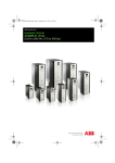
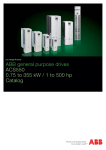
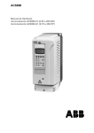
1
ABB Standard Drives ACS510-01 1.1 ~ 160 kW Technical Catalogue Two ways to select your drive Choice 1: Simply contact your local ABB drives sales office (see page 15) and let them know what you want. Use page 3 as a reference section for more information. Type code: 1 2 3 4 5 6 7 8 9 2 OR ACS510 Product series Rating and types Voltages Electromagnetic compatibility Construction Dimensions Assistant control panel Options Technical data Technical specification Control connections Services Contact and web infromation 3ABD00017601 Rev E EN 2010-09-01 Choice 2: Build up your own ordering code using the simple 6-step approach below. Each step is accompanied by a reference to a page that is filled with useful information. - 01 - 03A3 - 4 + B055 Contents ABB standard drives, ACS510 ABB standard drives.............................................................................4 Feature.........................................................................................4 Rating, types and voltages.................................................................5 Electromagnetic compatibility . ......................................................5 Constructions.........................................................................................6 Dimensions..............................................................................................6 Assistant control panel........................................................................7 Basic control panel..................................................................7 Control panel frame size.......................................................7 Options.....................................................................................................8 How to select options............................................................8 Available options.....................................................................8 Output chokes..........................................................................8 Panel mounting kit..................................................................9 Hole dimension for ACS-CP-cabinet kit...........................9 Plug-in options...................................................................... 10 Brake unit and choppers.................................................... 11 Technical data...................................................................................... 12 Cooling..................................................................................... 12 Fuse connections.................................................................. 12 Technical specification..................................................................... 13 Control connections.......................................................................... 14 Services.................................................................................................. 15 www.abb.com/motors&drives...................................................... 15 3ABD00017601 Rev E EN 2010-09-01 3 ABB standard drives ACS510 - 01 - 03A3 - 4 + ABB standard drives B055 ABB ACS510 drive promises ABB standard drives are simple to buy, install, configure and use, saving considerable time. They are widely available through ABB channel partners, hence the use of the term standard. The drives have common user and process interfaces with fieldbuses, common software tools for sizing, commissioning, maintenance and common spare parts. Applications Precise delivery Quick installation Rapid start-up Trouble-free use Highlights ABB standard drives can be used in a wide range of industries. Typical applications include pump, fan and constant torque use, such as conveyors. ABB standard drives are ideal in those situations where there is a need for simplicity to install, commission and use and where customizing or special product engineering is not required. Perfect match for industrial pumps and fans Advanced control panel providing intuitive operation Patent pending swinging choke for superior harmonic reduction Cycle soft start Multiple U/F curves Override mode Integral RFI filter for 1st and 2nd environment as standard CE approved What are its main features? Feature Advantage Benefit PFC application Up to 7 (1+ 6) pumps More pumps can be switched on and off Perfect match for SPFC Cycle soft start Each pump can be regulated in turn industrial fans and Mutiple U/F curve Freely defined 5 point U/F curve More wide and flexible application Override mode Emergency application in ventilator More safe and reliable application PID 2 built-up PID controllers Flexible tension control by trimming PID pumps Two groups of patameter setting for PID1 Economical Intuitive features Noise optimization: Considerable motor noise reduction Increases switching frequency when temperature is reduced Reduce inverter noise and improve energy efficiency Controlled cooling fan: Drive is cooled only when necessary Flux opimization Disable or Enable by user Reduce the energy consumption and noise Energy efficiency Connectivity Simple to install: Reduce installation time Side by side installation Reduce installation space Easy connection of cables Secure cable connections Easy connection to external fieldbus systems through multiple Enviromental friendly as standard Other EMC I/Os and plug-in options 1st and 2nd environment RFI filters as standard No need for additional external filtering Chokes Swinging chokes - matches the right inductance to the right load, thereby Reduce Total Harmonic Distortion (THD) suppressing and reducing harmonics emissions up to 25% Advanced control Two soft-keys, function of which changes according to the panel state pane Fieldbus 4 Easy commissioning Built-in help button Fast set-up Changed parameters menu Quick access to recent parameter changes Built-in Modbus using RS 485 Rapid fault diagnosis Reduce cost 3ABD00017601 Rev E EN 2010-09-01 Ratings, types and voltages ACS510 - 01 - 03A3 - 4 Type code This is the unique reference number (shown above and in column 4, right) that clearly identifies your drive by power rating and frame size. Once you have selected the type code, the frame size (column 5) can be used to determine the drives dimensions, shown on the next page. Voltages ACS510 -01 is available in the following voltage range: 4 = 380 - 480 V Normal use For the majority of pump, fan and conveyor applications, select “Normal use” figures. If in doubt contact your local ABB sales office or your drives distributor - see page 15. SN kVA PN kW + B055 3-phase supply voltage 380-480 V Wall mounted units Ratings Type code Frame size SN kVA 2.3 3 4 5 6 9 11 16 20 25 30 41 50 60 70 100 120 140 PN kW 1.1 1.5 2.2 3 4 5.5 7.5 11 15 18.5 22 30 37 45 55 75 90 110 I2N A 3.3 4.1 5.6 7.2 9.4 11.9 17 25 31 38 46 60 72 88 125 157 180 205 ACS510-01-03A3-4 ACS510-01-04A1-4 ACS510-01-05A6-4 ACS510-01-07A2-4 ACS510-01-09A4-4 ACS510-01-012A-4 ACS510-01-017A-4 ACS510-01-025A-4 ACS510-01-031A-4 ACS510-01-038A-4 ACS510-01-046A-4 ACS510-01-060A-4 ACS510-01-072A-4 ACS510-01-088A-4 ACS510-01-125A-4 ACS510-01-157A-4 ACS510-01-180A-4 ACS510-01-195A-4 R1 R1 R1 R1 R1 R1 R2 R2 R3 R3 R3 R4 R4 R4 R5 R6 R6 R6 170 132 245 ACS510-01-246A-4 R6 200 160 290 ACS510-01-290A-4 R6 = Typical motor apparent output power in 400 V at normal use = Typical motor power in 400 V at normal use Electromagnetic compatibility EMC according to EN61800-3 1st environment restricted distribution for frame sizes R3, R4 with 75 m motor cables and for frame sizes R1, R2, R5, R6 with 100 m motor cables as standard. 2nd environment unrestricted distribution for frame sizes R1 to R4 with 300 m motor cables and for frame sizes R5 to R8 with 100 m motor cables as standard. These cable lengths are for EMC purposes only. Operational cable lengths are available in the output choke selection table on page 11. For longer motor cable lengths, external EMC filters are available on request. EMC standards in general EN 61800-3/A11 (2000), product standard EN 61800-3 (2004), product standard EN 55011, product family standard for industrial, scientific and medical (ISM) equipment 1st environment, unrestricted distribution Category C1 Group 1 Class B 1st environment, restricted distribution Category C2 Group 1 Class A 2nd environment, unrestricted distribution Category C3 Group 2 Class A 2nd environment, restricted distribution Category C4 Not applicable 3ABD00017601 Rev E EN 2010-09-01 5 Dimensions ACS510 - 01 - 03A3 - 4 + B055 Wall mounted units Wall-mounted drives Frame size H2 H1 R1 R2 R3 R4 R5 R6 1) R6 1) H1 mm Dimensions and weights IP21 / UL type 1 IP54 / UL type 12 H2 W D Weight H W D Weight mm mm mm kg mm mm mm kg 369 469 583 689 739 880 986 330 430 490 596 602 700 700 125 125 203 203 265 300 302 212 222 231 262 286 400 400 6.5 9 16 24 34 69 73 449 549 611 742 776 924 1119 W H1 = Height with cable connection box H2 = Height without cable connection box W = Width D = Depth Construction ACS510 - 01 - 03A3 - 4 + B055 “01” within the type code (shown above) varies depending on the drive mounting arrangement and power rating. Choose the correct one for your needs from the table below: 01 6 For IP54 units Wall mounted, frame size R1-R6 1.1 to 160 kW IP21 Built-in EMC filter Coated board Standard software Built-in Modbus interface Cable connection box Brake chopper in frame sizes R1-R2 Assistant control panel 3ABD00017601 Rev E EN 2010-09-01 234 245 253 284 309 423 423 8.2 11.2 18.5 26.5 38.5 80 84 The demensions and weights apply to ACS510-01-246A-4 and ACS510-01-290A-4. D 213 213 257 257 369 410 410 If IP 54 is required, simply select “01” and then see page 8 to find the correct “Option” code. Assistant control panel The assistant control panel, which is delivered as standard, features a multilingual alphanumeric display, (EN, DA, DE, ES, FI, FR, IT, NL, PT, SE, US) or alternatively with code J416 (EN, DE, CZ, HU, PT, RU, TR) for easy drive programming. The control panel has various assistants and an inbuilt help function to guide the user. It includes a real time clock, which can be used during fault logging. The control panel can be used for copying parameters for back up or for downloading them to another drive. A large graphical display and soft keys make it extremely easy to navigate. Name Start-up Drive start Stop Drive stop Up Alter parametre/Increase reference Down Alter parametre/Decrease reference Local/ Remote Switch between Local (control panel)and Remote (I/O or other control source). Built-in help button Help Soft key1 Soft key2 Fuction of which changes according to the panel state Fuction of which changes according to the panel state Basic control panel Control panel frame size The basic control panel features a single line numeric display. The panel can be used to control the drive, set the parameter values or copy them from one drive to another. 3ABD00017601 Rev E EN 2010-09-01 7 Options ACS510 - 01 - 03A3 - 4 Panel mounting kit + B055 OPMP-01 kit and mounting hole dementions Two optional mounting kits for control panel: ■■ ACS-CP-EXT ■■ OPMP-01 To attach the control panel to the outside of a larger enclosure, two panel mounting kits are available. A simple and cost-effi cient installation is possible with the ACS/H-CP-EXT kit, while the OPMP-01 kit provides a more user-friendly solution, including a panel platform that enables the panel to be removed in the same way as a drive-mounted panel. The panel mounting kits include all hardware required, including 3 m extension cables and installation instructions. How to select options The options shown in the table are available within the ACS510 range. Most of them have an associated 4-figure option code, which is shown in the table. It is this code that replaces B055 in the type code above. External options require a separate order line and material or type code number. 1) 2) 3) 8 Ordering with a separate material code number. One slot available for relay or encoder. One slot available for fieldbus adapter. Modbus inbuilt as standard. 3ABD00017601 Rev E EN 2010-09-01 Available options Protection class B055 Control panel 0J400 J404 - 1) I/O options2) L511 Fieldbus3) K451 K452 K454 - 1) - 1) - 1) IP54 If no control panel is required Basic control panel ACS-CP-C Panel mounting kit ACS/H-CP-EXT ACS-CP-cabinet Relay output extension OREL-01 DeviceNet LonWorks Profibus-DP CANOpen ControlNet RDNA-01 RLON-01 RPBA-01 RCAN-01 RCNA-01 RETA-01 Ethernet Options Control interfaces ACS510 - 01 - 03A3 - 4 + B055 Output chokes Output chokes are used when motor cables above normal length are required.Cable can be roughly 1.5 times standard cable length, see below. Type code Frame size Nominal current I2N A UN = 380 - 480 V (380, 400, 415, 440, 460, 480 V) ACS510-01-03A3-4 R1 ACS510-01-04A1-4 R1 ACS510-01-05A6-4 R1 ACS510-01-07A2-4 R1 ACS510-01-09A4-4 R1 ACS510-01-012A-4 R1 ACS510-01-017A-4 R2 ACS510-01-025A-4 R2 ACS510-01-031A-4 R3 ACS510-01-038A-4 R3 ACS510-01-046A-4 R3 ACS510-01-060A-4 R4 ACS510-01-072A-4 R4 ACS510-01-088A-4 R4 ACS510-01-125A-4 R5 ACS510-01-157A-4 R6 ACS510-01-180A-4 R6 ACS510-01-195A-4 R6 ACS510-01-246A-4 R6 ACS510-01-290A-4 R6 Output choke type code 1) Choke thermal current I A Max. cable length without choke 2) m Max. cable length with choke 3) m 3.3 4.1 5.6 7.2 9.4 11.9 17 25 31 38 46 60 72 88 125 157 180 205 245 NOCH-0016-6X NOCH-0016-6X NOCH-0016-6X NOCH-0016-6X NOCH-0016-6X NOCH-0016-6X NOCH-0016-6X NOCH-0030-6X NOCH-0030-6X NOCH-0030-6X NOCH-0070-6X NOCH-0070-6X NOCH-0070-6X NOCH-0070-6X NOCH-0120-6X FOCH-0260-70 FOCH-0260-70 FOCH-0260-70 FOCH-0260-70 19 19 19 19 19 19 19 41 41 41 112 112 112 112 157 289 289 289 289 100 100 100 100 100 100 200 200 200 200 200 200 200 200 300 300 300 300 300 150 150 150 150 150 150 250 250 250 250 300 300 300 300 300 300 300 300 300 290 FOCH-0320-50 445 300 300 The last digit of the output choke type defines the degree of protection; X stands for 2 = IP22 or 5 = IP54, 0 = IP00 2) Cable lengths according to 4 kHz switching frequency 3) Maximum switching frequency to be used with du/dt filter is 4 kHz 1) Dimensions NOCH-0016-62/65 A mm 199 B mm 323 C mm 154 NOCH-0030-62/65 249 348 172 9 NOCH-0070-62/65 279 433 202 15.5 NOCH-0120-62/65 308 765 256 45 Type code Weight kg 6 Note An output choke does not improve the EMC performance of the drive. To fulfil local EMC requirements use sufficient RFI filtering. For more information refer to the ACS510 Technical reference. Please consult local ABB to get FOCH information. 3ABD00017601 Rev E EN 2010-09-01 9 Options ACS510 - 01 - 03A3 - 4 + B055 Relay output extension option module This plug-in option offers three additional relay outputs. They can be used, for example, in pump and fan control or many supervisory functions. All the relays can be programmed to on/off by using the assistant control panel’s clock. Alternatively, fieldbus can be used to control any external components in the system. Analog I/O Plug-in fieldbus module The plug-in fieldbus options bring connectivity to major automation systems. A single twisted pair avoids large amounts of conventional cabling, thereby reducing cost and increasing system reliability. ACS510 supports the following fieldbus options: DeviceNet LONWORKS PROFIBUS DP CANopen ControlNet Ethernet For type codes see page 8 10 3ABD00017601 Rev E EN 2010-09-01 Digital inputs Relay outputss Built-in Modbus using RS 485 Options Brake units and choppers W H Frame sizes R1 to R2 are delivered with integrated brake choppers as standard. Other units can use the compactsized brake units which include brake chopper and resistor. For more information please refer to the ACS-BRK Brake Units Installation and Start-up Guide. D Dimensions Width (W) mm 150 270 Height (H) mm 500 600 Depth (D) mm 347 450 Weight kg 7.5 20.5 Brake unit type code ACS-BRK-C ACS-BRK-D Brake choppers Rsel Ppeak Prated (cont.) [Ohm] [kW] [kW] 200 3.1 0.36 200 3.1 0.36 200 3.1 0.36 80 7.8 0.79 80 7.8 0.79 80 7.8 0.79 80 7.8 0.79 80 7.8 0.79 32 12 2 10.5 42 7 10.5 42 7 10.5 42 7 10.5 42 7 10.5 42 7 4 83 9 4 113 9 Type code Frame size Chopper R1 R1 R1 R1 R1 R1 R2 R2 R3 R3 R3 R4 R4 R4 R5 R6 ACS510-01-03A3-4 ACS510-01-04A1-4 ACS510-01-05A6-4 ACS510-01-07A2-4 ACS510-01-09A4-4 ACS510-01-012A-4 ACS510-01-017A-4 ACS510-01-025A-4 ACS510-01-031A-4 ACS510-01-038A-4 ACS510-01-046A-4 ACS510-01-060A-4 ACS510-01-072A-4 ACS510-01-088A-4 ACS510-01-125A-4 ACS510-01-157A-4 Internal Internal Internal Internal Internal Internal Internal Internal BRK-C BRK-D BRK-D BRK-D BRK-D BRK-D NBRA-656C NBRA-656C R6 ACS510-01-180A-4 NBRA-657C 4 135 R6 ACS510-01-195A-4 NBRA-657C 2.7 165 R6 ACS510-01-246A-4 NBRA-658C 2.7 198 R6 ACS510-01-290A-4 NBRA-658C 1.7 229 Rtype WxHxD CBR-V 210 DT 281 200R CBR-V 210 DT 281 200R CBR-V 210 DT 281 200R CBR-V 460 DT 281 80R CBR-V 460 DT 281 80R CBR-V 460 DT 281 80R CBR-V 460 DT 281 80R CBR-V 460 DT 281 80R Built-In Built-In Built-In Built-In Built-In Built-In SAFUR125F500 SAFUR125F500 130 x 345 x 120 130 x 345 x 120 130 x 345 x 120 130 x 595 x 120 130 x 595 x 120 130 x 595 x 120 130 x 595 x 120 130 x 595 x 120 150 x 500 x347 270 x 600 x 450 270 x 600 x 450 270 x 600 x 450 270 x 600 x 450 270 x 600 x 450 Consult ABB Consult ABB 9 SAFUR125F500 Consult ABB 13.5 SAFUR200F500 Consult ABB 13.5 SAFUR200F500 Consult ABB 21 2xSAFUR210F575 Consult ABB 3ABD00017601 Rev E EN 2010-09-01 11 Technical data Cooling Fuse connections ACS510 is fitted with cooling air fans. The cooling air must be free from corrosive materials and not above the maximum ambient temperature of 40oC (50oC with derating). For more specific environmental limits see page 5. Standard fuses can be used with ABB standard drives. For input fuse connections see tables below. Recommended input protection fuses for 380 - 480 V units Cooling air flow 380 - 480 V units Type code Frame size Heat dissipation Type code ACS510-01-03A3-4 ACS510-01-04A1-4 ACS510-01-05A6-4 ACS510-01-07A2-4 ACS510-01-09A4-4 ACS510-01-012A-4 ACS510-01-017A-4 ACS510-01-025A-4 ACS510-01-031A-4 ACS510-01-038A-4 ACS510-01-046A-4 ACS510-01-060A-4 ACS510-01-072A-4 ACS510-01-088A-4 ACS510-01-125A-4 ACS510-01-157A-4 ACS510-01-180A-4 ACS510-01-195A-4 ACS510-01-246A-4 R1 R1 R1 R1 R1 R1 R2 R2 R3 R3 R3 R4 R4 R4 R5 R6 R6 R6 R6 W 40 52 73 97 127 172 232 337 457 562 667 907 1120 1440 1940 2310 2810 3050 3850 ACS510-01-290A-4 R6 4550 IEC fuses Fuse type *) Air flow Frame size UL fuses Fuse type BTU/hr 137 178 249 331 434 587 792 1151 1561 1919 2278 3098 3825 4918 6625 7889 9597 10416 13148 m3/h 44 44 44 44 44 44 88 88 134 134 134 280 280 280 350 405 405 405 540 ft3/min 26 26 26 26 26 26 52 52 79 79 79 165 165 165 205 238 238 238 318 ACS510-01-03A3-4 ACS510-01-04A1-4 ACS510-01-05A6-4 ACS510-01-07A2-4 ACS510-01-09A4-4 ACS510-01-012A-4 ACS510-01-017A-4 ACS510-01-025A-4 ACS510-01-031A-4 ACS510-01-038A-4 ACS510-01-046A-4 ACS510-01-060A-4 ACS510-01-072A-4 ACS510-01-088A-4 ACS510-01-125A-4 ACS510-01-157A-4 ACS510-01-180A-4 ACS510-01-195A-4 ACS510-01-246A-4 R1 R1 R1 R1 R1 R1 R2 R2 R3 R3 R3 R4 R4 R4 R5 R6 R6 R6 R6 A 10 10 10 10 10 16 16 25 35 50 50 63 80 125 160 200 250 250 250 gG gG gG gG gG gG gG gG gG gG gG gG gG gG gG gG gG gG gG A 10 10 10 10 15 15 20 30 40 50 60 80 90 125 175 200 250 250 350 UL Class T UL Class T UL Class T UL Class T UL Class T UL Class T UL Class T UL Class T UL Class T UL Class T UL Class T UL Class T UL Class T UL Class T UL Class T UL Class T UL Class T UL Class T UL Class T 15539 540 318 ACS510-01-290A-4 R6 315 gG 315 UL Class T Free space requirements Enclosure type Wall mounted *) 12 According to IEC-60269 standard. 3ABD00017601 Rev E EN 2010-09-01 Space above mm 200 Space below mm 200 Space on left/right mm 0 Technical specification ACS510 - 01 - 03A3 - 4 + B055 Programmable control connections Mains connection Voltage and power range 3-phase, 380 to 480 V, +10/-15%, 1.1 - 160 kW Auto-identification of input line Frequency 48 to 63 Hz Power factor 0.98 Motor connection Two analog inputs Voltage signal Current signal Potentiometer reference value Maximum delay Resolution Accuracy 0 (2) to 10 V, Rin > 312 k¦¸single-ended 0 (4) to 20 mA, Rin = 100¦¸single-ended10 V ±2% max. 10 mA, R < 10 kΩ 12 to 32 ms 0.1% ±1% Voltage 3-phase, from 0 to USUPPLY Two analog outputs 0 (4) to 20 mA, load < 500¦¸ Frequency 0 to 500 Hz (0 to 50HZ for N688, 0 to 55HZ for N689) Accuracy ±3% Auxiliary voltage 24 V DC ±10%, max 250 mA Continuous loading capability Rated output current I2 Six digital inputs Input impedance Maximum delay Overload capacity At normal use 1.1 x I2N for 1 minute every 10 minutes . 12 V... 24 V DC with internal or external supply, PNP and NPN 2.4 kΩ 5 ms ± 1 ms (constant torque at a max ambient temperature of 400C) (at a max. ambient temperature of 400C) Switching frequency Standard Selectable Default 4 kHz 1 kHz, 4 kHz, 8 kHz, 12 kHz Acceleration time 0.1 to 1800 s Deceleration time 0.1 to 1800 s Environmental limits Ambient temperature -15 to 40oC 40 to 50oC No frost allowed Switch frequency 4 kHz, derating please contact supplier Altitude Output current Rated current available at 0 to 1000 m reduced by 1% per 100 m over 1000 m to 2000 m Relative humidity lower than 95% (without condensation) Protection class IP21 or IP54 Enclosure colour NCS 1502-Y, RAL 9002, PMS 420 C Contamination levels IEC 721-3-3 No conductive dust allowed Class 1C2 (chemical gases), Class 1S2 (solid particles) Class 2C2 (chemical gases), Class 2S2 (solid particles)) Class 3C2 (chemical gases), Class 3S2 (solid particles) Transportation Storage Operation Three relay outputs Maximum switching voltage Maximum switching current Maximum continuous current 250 V AC/30 V DC 6 A/30 V DC; 1500 V A/230 V AC 2 A rms Serial communication RS 485 Modbus protocol Protection limits Overvoltage trip limits Running V DC Start inhibit V DC 842 (corr. to 595 V input) 661 (corr. to 380 - 415 V input), Undervoltage trip Running V DC Start inhibit V DC 333 (corr.to 247 V input) 436 (corr.to 380 - 415 V input), EMC (according to EN61800-3) 1st environment restricted distribution for frame sizes R3, R4 with 75 m motor cables and for frame sizes R1, R2, R5, R6 with 100 m motor cables. 2nd environment unrestricted distribution with 300 m motor cables for frame sizes R1 to R4 and 100 m motor cables for frame sizes R5 to R6 as standard. For longer motor cable lengths, external EMC filters are available on request. 3ABD00017601 Rev E EN 2010-09-01 13 Control connections ACS510 - 01 - 03A3 - 4 + B055 These connections are shown as examples only. Please refer to the ACS510 User’s Manual, chapter Installations, for more detailed information. 0 - 20 mA Ground the cable screen on the sourcing end ramp pair sel. const. speed 1 fwd/ rev 10 11 12 13 14 15 16 17 18 start/ stop DI configuration NPN connected (sink) RS 485 Multidrop application SCR B A GND B A GND SCR 14 3ABD00017601 Rev E EN 2010-09-01 +24V GND DCOM DI1 DI2 DI3 DI4 DI5 DI6 19 20 21 RO1C RO1A RO1B 22 23 24 RO2C RO2A RO2B 25 26 27 RO3C RO3A RO3B Other Modbus device AI1: AI2: 1 2 3 4 5 6 7 8 9 R<10 kΩ 0-10 V 0(4)-20 mA + 24V const. speed 1 DI configuration PNP connected (source) with external power supply- ACS510 X3 28 SCR 29 B 30 A 31 AGND 32 SCR start/ stop fwd/ rev + 0V DIP switch RS 485 interface SCR AI1 AGND +10V AI2 AGND AO1 AO2 AGND 10 11 12 13 14 15 16 17 18 +24V GND DCOM DI1 DI2 DI3 DI4 DI5 DI6 19 20 21 RO1C RO1A RO1B 22 23 24 RO2C RO2A RO2B 25 26 27 RO3C RO3A RO3B Not termin. Signal termination is selected by DIP switch DIP switch analog inputs AI1: AI2: NO NO DIP switch analog inputs ACS510 X1 NO NO R<10 kΩ SCR AI1 AGND +10V AI2 AGND AO1 AO2 AGND NO 1 2 3 4 5 6 7 8 9 NO ACS510 X1 0-10 V 0-10 V Services SupportLine services Training services ABB has created a lifecycle management model for ABB drives products and systems to provide customers with maximum profit for purchased assets by maintaining high availability, eliminating unplanned repair costs and extending system lifetime. The lifecycle management model comprises a palette of dedicated services for the entire lifecycle of the ABB drive, ACS510. The services begin with drive dimensioning, professional commissioning and training, continue with spare part services, proactive scheduled maintenance programs and support services and end with smooth transition to new technology and recycling at the end of the product lifecycle. Installation and commissioning ABB offers dedicated training on ABB drives for your service and operating personnel. Upon successful completion of the training course your personnel will have acquired the skills to use ABB drives correctly and safely, and also to get the best results from their application. The training courses are broken down into modules that allow for customization of the contents depending on the objectives and skill levels of the participants. For more information on our training services, please contact your local ABB representative or visit the ABB University web pages at http://www.abb.com/ abbuniversity. ABB BeiJing 24x 365 hotline service ABB’s professional start-up service uses certified engineers to install and adjust ABB drives according to the application requirements as well as to instruct the user on how to operate the drive. The ABB BeiJing Service Hot Line provides fast, easy, reliable access to our power electronics support engineers. This service is available 24 hours per day, 365 days per year. Drives product lifecycle management Product lifecycle phases: Active (~5 to 10 years) ■ Product, spare parts and related lifecycle services have been released for sale. ■ Service products provide fast drive start-up and they support ease-of-use from day one. ■ Migration from limited and obsolete products is supported. Classic (~7 to 10 years) ■ Product is no longer manufactured, but drive modules are available for spare parts and extensions. ■ Full range of lifecycle services focused on drive reliability and performance is provided. ■ Enhancements are available as far as technology permits. Guaranteed product support Limited Obsolete (~3 to 5 years) ■ Repair services and parts are available as long as materials can be obtained. ■ ABB recommends migration to active products. ■ Recycling services are available (contingent on the market). ■ ABB cannot guarantee availability of product support for technical reasons or at a reasonable cost. ■ Many ABB products have been and will be supported for over 20 years. Limited product support ABB follows a four-phase model for managing the lifecycles of its drives for enhanced customer support and improved efficiency. Many ABB products have been and will be supported. 3ABD00017601 Rev E EN 2010-09-01 15 3ABD00017601 Rev E EN 2010-09-01 ABB Beijing Drive Systems Co.,Ltd. No.1, Block D, A-10 jiuxianqiao Beilu Chaoyang District Beijing, 100015 Tel : +86 10 58217788 Fax: +86 10 58217518/58217618 Hot-line: +86 400 810 8885 Web Site :http://www.abb.com/motors&drives