1
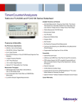
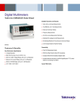
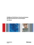
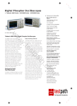
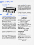
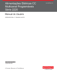
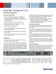
Microwave/Counter/Analyzer & Integrated Power Meter
MCA3000 Series Datasheet
Available Functions and Features
Automated Measurements: Frequency, Period, Ratio, Time Interval,
Time Interval Error, Pulse Width, Rise/Fall Time, Phase Angle, Duty
Cycle, Maximum Voltage, Minimum Voltage, Peak-to-Peak Voltage
Integrated Power Meter
Multi-parameter Display
Trend Plot Mode
Measurement Statistics Mode
Features & Benefits
Histogram Mode
Key Performance Specifications
Allan Deviation
27 GHz and 40 GHz Models
Microwave Analyzer Channel with CW or Burst
Two 300 MHz General-purpose Channels
Zero Dead-time Frequency/Period Measurements
Connectivity
100 ps Single-shot Time Resolution
USB Device and GPIB Ports on Rear Panel for Quick PC Connectivity
12 Digit/s Frequency Resolution, 14 Digit Display
GPIB Interface Supports Full SCPI-compatible Programmability and
offers an Emulation Mode for Plug-and-Play Replacement in Existing
ATE Systems
25 ms (Auto) or Zero (Manual) Acquisition Time
3 mV Voltage Resolution
Optional 1.5×10⁻⁸ Ultra High-stability Oven Time Base
–35 dBm to +10 dBm Power Range
Measurement Throughput
250k Sample/s Data Transfer Rate to Internal Memory
(Up to 750k samples stored)
5k Sample/s Data Transfer Rate over USB/GPIB Bus
(Block mode)
External Arming Input
10 MHz Reference Oscillator Output
Includes National Instrument’s LabVIEW SignalExpress™ TE Limited
Edition Software for Connecting Your Bench
Optional TimeView™ Software Available for Modulation Domain Analysis
3-year Warranty
Datasheet
Feature-rich Tools for Precision
Measurements
The MCA3000 Microwave Counter Series outperforms every microwave
counter on the market today in terms of resolution, speed, and acquisition
time. Including an integrated power meter, the MCA Series packs many
different functions into one feature-rich instrument.
With industry-leading frequency and time resolution, the MCA Series
comes standard with internal memory and a fast data transfer rate of
250k Samples/s to memory. In addition, the multi-parameter display
shows auxiliary measurements alongside your main measurement to
provide you with the results you need at a glance. With the industry’s
most comprehensive analysis modes, including measurement statistics,
histograms, and trend plots, you have the tools you need to quickly and
accurately analyze your signal.
Besides being an outstanding microwave counter, the MCA3000 Series also
serves as a general-purpose timer/counter with two additional 300 MHz
inputs.
Industry-leading Performance for Demanding
Designs
Fast high-resolution frequency or power measurements with a very short
acquisition time of 25 ms (Auto) or zero (Manual) is essential for validating
today’s complex designs. For calibration and metrology applications, the
MCA Series offers very high accuracy through a stable internal OCXO time
base, low systematic time interval A-B error, and high resolution.
Fast Throughput Reduces Test Time
The MCA Microwave Counter Series offers industry-best throughput,
saving you up to 90% on your testing time compared to other microwave
timer/counters on the market. Up to 250,000 measurement results per
second can be stored in the internal memory. Alternatively, you can transfer
up to 5,000 measurement results per second in Block mode through the
GPIB or USB interface.
Power Measurements
With an integrated power meter, the MCA Series provides measurement of
frequency and power with a single connection at any supported frequency
2
www.tektronix.com
Multi-parameter Display.
level. For the first time, variations in signal power can be seen, collected,
and analyzed in the same manner as frequency, both numerically and
graphically. With 0.01 dBm at 100 ms measuring time resolution and a wide
power range from –35 dBm to +10 dBm, you have the flexibility for a broad
range of power measurement applications.
Analyze Your Device with the Industry’s Only
Graphical Display
With the unique display of the MCA Series, you can measure multiple
parameters of the same signal from one test connection. To reveal signal
quality issues like drift, intermittent transients, and stability, you can view the
data as a real-time trend plot or a histogram with the MCA Series graphical
display mode, or you can use measurement statistics to track how signal
parameters are changing over time. A single-button Analyze mode gives
you fast insight into the behavior of your device right on the timer/counter’s
display.
Multi-parameter Display
With the multi-parameter display, you can read important auxiliary
measurement values (such as Vmax, Vmin, Vp-p, and more) displayed with your
main frequency, time, period, or phase measurements. With one glance,
you can see the information you need to quickly assess your device’s
performance.
With 3 input channels, you can measure the relationship between different
signals. For example, you can measure the phase relationship between
the input and output signals of your device. You can read other critical
parameters simultaneously, such as the test frequency of the signal and the
voltage ratio (in dB), in one glance with the multi-parameter display.
Microwave/Counter/Analyzer & Integrated Power Meter — MCA3000 Series
Trend Plot Analysis.
Tektronix TimeView™ Software.
Measurement Statistics.
Histogram Plot.
Measurement Trend Plots
Depending on your test case, your signal parameters may change from
instant to instant. With the Trend Plot Analysis mode, you can graphically
plot the trend of a measured value over time.
Measurement Statistics
With integrated statistics processing, you can calculate the average,
standard, and Allan deviation of a measurement, as well as track the
minimum and maximum measured values, all with the push of a button.
Histogram Plots
To graphically see the average and standard deviation of a set of
measurements, you can use the histogram function to see the distribution of
measurement results.
Optional Modulation Domain Analysis
With the optional Tektronix TimeView™ software (TVA3000), the MCA
Series products become high-performance modulation domain analyzers.
With high measurement speeds (up to 250k measurement/s) and memory
depth at 750k, fast frequency changes can be captured in real time and
then analyzed with TimeView. This comprehensive software tool allows for
remote instrument control, and the analysis and display of measurement
results in a choice of graphs. For example, results can be displayed as
raw data, statistical histogram, waveform graph (as if you were using an
oscilloscope), or as an FFT spectrum graph. TimeView further allows
analysis of modulation parameters like modulation depth or frequency
modulation index.
Designed to Make Your Work Easier
The MCA Microwave Counter Series are designed with the ease of use and
familiar operation you have come to expect from Tektronix.
Intuitive Operation
Menu-oriented settings reduce the risk of mistakes. With dedicated and
menu-driven front-panel buttons, you will have fast access to frequently
used functions and parameters, reducing setup time. For example, a
single-touch Analyze key toggles you between Statistics, Trend Plot, and
Histogram modes.
Autoset Function
Similar to Tektronix oscilloscopes, the front-panel Autoset button will
automatically set optimum trigger levels and hysteresis adapted to the
actual signal applied.
Easy PC Connectivity
Connect to your PC with the rear-panel GPIB or USB device ports. The
GPIB interface operates in SCPI/GPIB for plug-and-play replacement in
existing ATE systems or easy integration into larger test systems. If desired,
an emulation mode for existing timer/counters is available.
www.tektronix.com
3
Datasheet
Connect Your Bench for Intelligent Debug
Frequency Burst A, B, C
Easily capture, save, and analyze measurement results from your MCA
Microwave Counter Series with the special Tektronix Edition of National
Instruments LabVIEW SignalExpress™ software. Every MCA3027
and MCA3040 ships with a free copy of the Limited Edition version of
SignalExpress for basic instrument control, data logging, and analysis. The
optional Professional Edition offers over 200 built-in functions that provide
additional signal processing, advanced analysis, sweeping, limit testing,
and user-defined step capabilities.
Characteristic
SignalExpress supports the range of Tektronix bench instruments*1
enabling you to connect your entire test bench. You can then access the
feature-rich tools packed into each instrument from one intuitive software
interface. This allows you to automate complex measurements requiring
multiple instruments, log data for an extended period of time, time-correlate
data from multiple instruments, and easily capture and analyze your results,
all from your PC. Only Tektronix offers a connected test bench of intelligent
instruments to simplify and speed debug of your complex design.
Performance You Can Count On
In addition to industry-leading service and support, every MCA Series
Microwave/Counter/Analyzer comes backed with a three-year standard
warranty.
*1 For a complete listing of Tektronix instruments supported by NI LabVIEW Signal Express, visit
www.tektronix.com/signalexpress.
Characteristics
Range
Input A, B
Input C
Acquisition C
Minimum Burst Duration
Minimum Pulses in Burst
Input A, B
Input C
PRF Range
Start Delay
Aux Parameters
Description
0.001 Hz to 300 MHz
300 MHz to 27 GHz or 40 GHz
Manual
Down to 40 ns
3 (6 above 160 MHz)
3 × prescaler factor
0.5 Hz to 1 MHz
10 ns to 2 s, 10 ns resolution
PRF
Period A, B (Single or Average), C (Average)
Characteristic
Description
Mode
Range
Input A, B
Input C
Resolution
Acquisition C
Acquisition time
Aux Parameters
Input A, B
Input C
Single, Average
3.3 ns to 1000 s (single, average)
3.3 ns down to 37 ps (27 GHz) or 25 ps (40 GHz)
100 ps (single); 12 digit/s (average)
Auto or Manual (within ±40 MHz)
25 ms in Auto (typical)
Vmax, Vmin, Vp-p
Power C in dBm or W
Measuring Functions
Ratio A/B, B/A, C/A, C/B
All measurements are displayed with a large main parameter value and smaller
auxiliary parameter values (with less resolution). Some measurements are only
available as auxiliary parameters.
Characteristic
Description
Range
Input Frequency
Input A, B
Input C
Aux Parameters
(10–9) to 1011
Frequency A, B, C
Characteristic
Range
Input A, B
Input C
Resolution
Acquisition C
Acquisition time
Aux Parameters
Input A, B
Input C
Description
DC to 300 MHz
300 MHz to 27 GHz or 40 GHz
12 digits in 1 s measuring time
Auto or Manual
25 ms in Auto (typical)
Vmax, Vmin, Vp-p
Power C in dBm or W
0.1 Hz to 300 MHz
300 MHz to 27 GHz or 40 GHz
Freq 1, Freq 2
Time Interval A to B, B to A, A to A, B to B
Characteristic
Description
Range
Normal calculation: 0 ns to +106 s
Smart calculation: –106 s to +106 s
100 ps single
1.6 ns
Smart Time Interval to determine sign (A before B or A
after B)
Resolution
Min Pulse Width
Smart Calculation
Positive and Negative Pulse Width A, B
Characteristic
Description
Range
Min Pulse Width
Aux Parameters
2.3 ns to 106 s
2.3 ns
Vmax, Vmin, Vp-p
Rise and Fall Time A, B
4
www.tektronix.com
Characteristic
Description
Range
Trigger Levels
Min Pulse Width
Aux Parameters
1.5 ns to 106 s
10% and 90% of signal amplitude
1.6 ns
Slew rate, Vmax, Vmin
Microwave/Counter/Analyzer & Integrated Power Meter — MCA3000 Series
Positive and Negative Duty Factor A, B
Characteristic
Description
Range
Frequency Range
Aux Parameters
0.000001 to 0.999999
0.1 Hz to 300 MHz
Period, pulse width
Phase A Relative B, B Relative A
Characteristic
Description
Range
Resolution
–180° to +360°
Single cycle: 0.001° to 10 kHz, decreasing to 1°
>10 MHz. Resolution can be improved by averaging
(statistics)
Up to 160 MHz
Freq (A), Va/Vb (in dB)
Frequency Range
Aux Parameters
Vmax, Vmin, Vp-p A, B
Characteristic
Description
Range
–50 V to +50 V, –5 V to +5 V
Range is limited by the specification for max input
voltage without damage (see input A, B)
Frequency Range
DC, 1 Hz to 300 MHz
Mode
Vmax, Vmin, Vp-p
Resolution
3 mV
Uncertainty (5 V range, typical)
DC, 1 Hz to 1 kHz
1% + 15 mV
1 kHz to 20 MHz
3% + 15 mV
20 to 100 MHz
10% + 15 mV
100 to 300 MHz
30% + 15 mV
Aux Parameters
Vmin, Vmax, Vp-p
Time Stamping A, B, C
Raw time-stamp data together with pulse counts on inputs A, B, or C, accessible
through GPIB or USB only.
Characteristic
Description
Max Sample Speed
Max Frequency
Time-stamp Resolution
See GPIB specifications
160 MHz
100 ps
Power C
Characteristic
Range
Power
Frequency
Display Units
Resolution
Accuracy (Typical)
Acquisition
Acquisition Time
Aux Parameters
Description
–35 dBm to +10 dBm
300 MHz to 27 GHz or 40 GHz
dBm (default) or W
0.01 dBm at 100 ms measuring time
<1 dBm to 27 GHz
<4 dBm to 40 GHz (MCA3040 only)
Auto or Manual (within ±40 MHz)
20 to 30 ms in Auto (typical)
Frequency C
Input and Output Specifications
Inputs A and B
Characteristic
Description
Frequency Range
DC Coupled: DC to 300 MHz
AC Coupled: 10 Hz to 300 MHz
1 MΩ / 20 pF or 50 Ω (VSWR ≤ 2:1)
Positive or negative
500 ps
Impedance
Trigger Slope
Max Channel Timing
Difference
Sensitivity
Attenuation
Dynamic Range (X1)
Trigger Level
Resolution
Uncertainty (X1)
AUTO trigger level
15 mVRMS (DC-200 MHz)
25 mVRMS (200-300 MHz)
X1, X10
30 mVp-p to 10 Vp-p within ±5 V window
Readout on display
3 mV
±(15 mV + 1% of trigger level)
Trigger level is automatically set to 50% point of input
signal (10% and 90% for rise/fall time)
Auto Hysteresis
Time
Min hysteresis window (hysteresis compensation)
Frequency
One-third of input signal amplitude
Analog LP Filter
Nominal 100 kHz, RC type
Digital LP Filter
1 Hz to 50 MHz cutoff frequency
Max Voltage without Damage
1 MΩ
350 V (DC + AC peak) to 440 Hz, falling to 12 VRMS (X1)
at 1 MHz
12 VRMS
50 Ω
Connector
BNC
Input C – 27 GHz or 40 GHz (MCA3027, MCA3040)
Characteristic
Description
Frequency Range
0.3 to 27 GHz or 40 GHz
Operating Input Voltage Range
–33 to +13 dBm
0.3 to 18 GHz
–29 to +13 dBm
18 to 20 GHz
–27 to +13 dBm
20 to 27 GHz
–23 to +13 dBm
27 to 40 GHz
Impedance
50 Ω nominal, AC coupled
VSWR
0.3 to 27 GHz
< 2.0:1 (typ.)
27 to 40 GHz
< 2.5:1 (typ.)
FM Tolerance
Manual acq.
50 MHzp-p; Frequency C >3.5 GHz
30 MHzp-p; Frequency C <3.5 GHz
Auto acq.
20 MHzp-p; for any Frequency C and modulation
frequency >0.1 MHz
AM Tolerance
Any modulation index (minimum signal must be within
sensitivity range)
Automatic Amplitude
10 dB separation between 2 signals within 30 MHz,
Discrimination
20 dB otherwise
Max Voltage without
+27 dBm (27 and 40 GHz models)
Damage
Overload Indication
ON when Input C power > +10 dBm
Connector
2.92 mm spark plug female
www.tektronix.com
5
Datasheet
Rear Panel Inputs and Outputs
Other Functions
Characteristic
Description
Characteristic
Description
Reference Input
Reference Output
Arming Input
Impedance
Frequency range
1, 5, or 10 MHz; 0.1 to 5 VRMS sine; impedance ≥1 kΩ
10 MHz; >1 VRMS sine into 50 Ω
Arming of all measuring functions
Approx. 1 kΩ
DC to 80 MHz
Measuring Time
20 ns to 1000 s for frequency, burst, and period average.
Single cycle for other measuring functions
Internal, external, or automatic
Freezes the result, until a new measurement is initiated
through a restart
Graphical indication on front panel and/or SRQ through
GPIB
Lower limit, upper limit
Off, or alarm if value is above, below, inside, or outside
limits
Stop or Continue
Numeric + Graphic
20. Instrument setups can be saved/recalled from
internal nonvolatile memory. 10 can be user protected
Backlit LCD graphics screen for menu control, numerical
readout, and status information
14 digits in Numerical mode
320 × 97 pixels
Auxiliary Functions
Trigger Holdoff
Characteristic
Description
Time Delay Range
20 ns to 2 s, 10 ns resolution
External Start and Stop Arming
Arming can be used to synchronize the frequency and power measurements with
the start of a burst signal. Minimum burst length must exceed 100 µs.
Characteristic
Description
Modes
Start and Stop Arming
Input Channels
A, B, or E (Ext. arming input)
Max Rep. Rate for Arming Signal
160 MHz
Channel A, B
80 MHz
Channel E
Start-time Delay Range 20 ns to 2 s, 10 ns resolution
Statistics
Characteristic
Description
Functions
Maximum, Minimum, Mean, ΔMax-Min, Standard
Deviation, and Allan Deviation
Numeric, histograms, or trend plots
2 to 2 × 10⁹ samples
Off, or capture values above, below, inside, or outside
limits
Pacing Time Range: 4 µs to 500 s
Display
Sample Size
Limit Qualifier
Measurement Pacing
Time-base Reference
Display Hold
Limit Alarm
Limit Values
Settings
On Alarm
Display
Stored Instrument
Setups
Display
Number of digits
Resolution
GPIB Interface
Characteristic
Description
Compatibility
IEEE 488.2-1987, SCPI 199953131A Compatibility
mode
SH1, AH1, T6, L4, SR1, RL1, DC1, DT1, E2
Interface Functions
Max Measurement Rate
GPIB
5k readings/s (Block mode)
500 readings/s (individual GET triggered)
To internal memory
250k readings/s
750k readings
Internal Memory Size
USB Interface
Characteristic
Description
USB Version
2.0 full speed (11 Mb/s)
Mathematics
Characteristic
Description
Calibration
Functions
(K*X+L)/M, (K/X+L)/M, or X/M-1. X is current reading
and K, L, and M are constants; set using the keyboard or
as frozen reference value (X0)
Characteristic
Description
Mode
Closed case, menu controlled
Calibration Frequencies 0.1, 1, 5, 10, 1.544, and 2.048 MHz
General Specifications
Environmental Data
Characteristic
Description
Class
Operating Temp
Storage Temp
Humidity
MIL-PRF-28800F, Class 3
0 °C to +50 °C
–40 °C to +71 °C
5-95% (10-30 °C)
5-75% (30-40 °C)
5-45% (40-50 °C)
Operating: 2,000 m
Storage: 12,000 m
Directive 2006/95/EC, EN61010-1, UL61010-1,
CAN/CSA C22.2 No. 61010-1
EU Directive 2004/108/EC, EN61326-1, EN61326-2-1,
Class A
Altitude
Safety
EMC
6
www.tektronix.com
Microwave/Counter/Analyzer & Integrated Power Meter — MCA3000 Series
Ordering Information
Power Requirements
Characteristic
Description
Basic Version
90 to 265 VRMS, 45 to 440 Hz, <40 W
Models
Model
Time-base Options
Characteristic
Standard,
Medium
Stability
High Stability
(HS)
Ultra High
Stability (US)
Time-base Type
OCXO
OCXO
OCXO
Uncertainty Due to –
Aging
Per 24h
<5×10–10*1
<3×10–10*1
<5×10–9*1
Per month
<6×10⁻⁸
<1×10⁻⁸
<3×10⁻⁹
Per year
<2×10⁻⁷
<5×10⁻⁸
<1.5×10⁻⁸
Temperature variation (typ. values)
<5×10⁻⁸
<5×10⁻⁹
<2.5×10⁻⁹
0-50 °C
<2×10⁻⁸
<1×10⁻⁹
<4×10⁻¹⁰
20-26 °C
<1×10⁻¹⁰
<1×10–11
<5×10–12
Short-term
Stability: t = 1 s
Root Allan
<1×10⁻¹⁰
<1×10–11
<5×10–12
Variance: t = 10 s
<1×10⁻⁷
<1×10⁻⁸
<5×10⁻⁹
Power-on Stability
30 min
10 min
10 min
Deviation versus
final value after
24h ON time,
after a warm-up
time of:
Total Uncertainty, for Operating Temperature 20 °C to 26 °C, at 2σ (95%)
Confidence Interval
<2.4×10⁻⁷
<0.6×10⁻⁷
<1.8×10⁻⁸
1 year after
calibration
<4.6×10⁻⁷
<1.2×10⁻⁷
<3.5×10⁻⁸
2 years after
calibration
*1 After 1 month of continuous operation.
Description
MCA3027
Microwave/Counter 27 GHz / 100 ps
MCA3040
Microwave/Counter 40 GHz / 100 ps
MCA3000 Series Includes: Microwave/Counter, line cord, calibration certificate,
Quick Start User Manual, CD-ROM with user manual (English, French, German,
Spanish, Simplified Chinese, Traditional Chinese, Korean, Russian, Japanese),
Programmer's Guide, Technical Specifications, Trial version of TimeView™ Software,
and CD-ROM with National Instruments LabVIEW SignalExpress™ Tektronix
Edition, Limited Edition Software.
Note: Please specify power plug when ordering.
Instrument Options
Option
Description
HS
US
High-stability Oven Time Base
Ultra High-stability Oven Time Base
Power Plug Options
Option
Description
A0
A1
A2
A3
A5
A6
A10
A11
North America
Universal Euro
United Kingdom
Australia
Switzerland
Japan
China
India
Physical
Dimension
mm
in.
Height
Width
Depth
90
210
395
3.6
8.25
15.6
Weight
kg
lb.
Net
Shipping
2.7
3.5
5.8
7.5
www.tektronix.com
7
Datasheet
Contact Tektronix:
ASEAN / Australasia (65) 6356 3900
Austria 00800 2255 4835*
Balkans, Israel, South Africa and other ISE Countries +41 52 675 3777
Belgium 00800 2255 4835*
Service Options
Option
Description
C3
C5
D1
R5
SILV600
Calibration Service 3 Years
Calibration Service 5 Years
Calibration Data Report
Repair Service 5 Years
Standard Warranty Extended to 5 Years
Brazil +55 (11) 3759 7627
Canada 1 800 833 9200
Central East Europe and the Baltics +41 52 675 3777
Central Europe & Greece +41 52 675 3777
Denmark +45 80 88 1401
Finland +41 52 675 3777
France 00800 2255 4835*
Germany 00800 2255 4835*
Recommended Accessories and Software
Accessory
Description
RMU2U
HCTEK4321
ACD4000
174-4401-xx
012-0991-xx
012-1256-xx
012-0482-xx
SIGEXPTE
Rackmount Shelf Kit for 2 Units
Hard Carrying Case
Soft Carrying Case
USB Host to Device Cable, 3 ft.
GPIB Cable, Double Shielded
BNC Male to BNC Male, Cable Shielded, 9 ft., 50 Ω
BNC Male to BNC Male, Cable Shielded, 3 ft., 50 Ω
National Instruments SignalExpress™ Tektronix Edition
Interactive Measurement Software – Professional
Version
TimeView™ Modulation Domain Analysis Software
TVA3000
Hong Kong 400 820 5835
India 000 800 650 1835
Italy 00800 2255 4835*
Japan 81 (3) 6714 3010
Luxembourg +41 52 675 3777
Mexico, Central/South America & Caribbean 52 (55) 56 04 50 90
Middle East, Asia, and North Africa +41 52 675 3777
The Netherlands 00800 2255 4835*
Norway 800 16098
People’s Republic of China 400 820 5835
Poland +41 52 675 3777
Portugal 80 08 12370
Republic of Korea 001 800 8255 2835
Russia & CIS +7 (495) 7484900
South Africa +41 52 675 3777
Tektronix is registered to ISO 9001 and ISO 14001 by SRI Quality System Registrar.
Spain 00800 2255 4835*
Sweden 00800 2255 4835*
Switzerland 00800 2255 4835*
Product(s) complies with IEEE Standard 488.1-1987, RS-232-C, and with Tektronix
Standard Codes and Formats.
Taiwan 886 (2) 2722 9622
United Kingdom & Ireland 00800 2255 4835*
USA 1 800 833 9200
* European toll-free number. If not accessible, call: +41 52 675 3777
Updated 10 February 2011
For Further Information. Tektronix maintains a comprehensive, constantly expanding
collection of application notes, technical briefs and other resources to help engineers working
on the cutting edge of technology. Please visit www.tektronix.com
Copyright © Tektronix, Inc. All rights reserved. Tektronix products are covered by U.S. and foreign patents,
issued and pending. Information in this publication supersedes that in all previously published material.
Specification and price change privileges reserved. TEKTRONIX and TEK are registered trademarks of
Tektronix, Inc. All other trade names referenced are the service marks, trademarks, or registered trademarks
of their respective companies.
25 Jul 2012
www.tektronix.com
3CW-25557-3