1
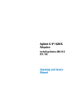
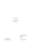
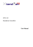
126
ELECTRONIC COUNTERS
CW Microwave Frequency Counters
HP5350B f 5351B f 5352B
10 Hz to 46 GHz without an external mixer
Exceptional sensitivity to -40 dBm
1 GHz/s tracking speed
60 ms acquisition time
100 measurements/s (HP-IB) in automatic mode
Three years of hardware support with Option W30
Low Acquisition Time: High Throughput
With acquisition time reduced to 60 ms in automatic, fast-acquisition
tracking mode (20 ms in manual mode), these high-speed counters can
significantly improve your measurement throughput
In bench-top applications, this high-speed throughput gives you
fast measurement response. The LCD will update measurements rapidly
to shorten evaluation time. For applications that require fast response to
source tuning, these counters are ideal solutions.
In systems environments, fast measurement throughput contributes to overall system efficiency. Delivering more than 100 measurements/s over HP-IB in automatic mode, these counters save money by
reducing test time.
1 GHz/s Tracking: Measuring Fast-Moving Signals
Fast acquisition offers fast tracking speed. With acquisition time below
60 ms, these counters can track source drift to 1 GHz/s effortlessly. For
example, when measuring the response of a voltage-controlled oscillator
(VCO) to voltage-source tuning, these counters track the changing frequency rapidly to measure transfer characteristics.
Instrument Drivers
HP 5350B, 5351B, 5352B Microwave Counters
The HP 5350B/5351B/5352B are automatic CW microwave frequency
counters that measure to 20,26.5, and 40 GHz (46 GHz with Option 005),
respectively. With resolution as fine as 1 Hz, these counters provide fast
and precise frequency measurements.
By integrating all microwave components onto a single hybrid GaAs
circuit, these counters offer high performance at low prices. Wide frequency coverage, exceptional sensitivity, fast tracking speed, high-measurement throughput, and wide FM tolerance are a few of the
high-performance features of these counters.
With a built-in microprocessor, the HP 5350B/5351B/5352B have
math capabilities such as measurement scaling and offset. These functions are useful for indirect measurements. Automatic amplitude discrimination automatically measures the frequency of the highest-amplitude signal in a multi-signal environment. Other convenience features
include diagnostic routines that perform tests on the counter for general
information and troubleshooting.
With high measurement throughput, the HP 5350B/5351B/5352B
are ideal components for test systems. Their English-like commands simplify systems integration by reducing programming time and effort. In
automatic test systems, the programmable alphanumeric liquid-crystal
display (LCD) can serve as a message center; if operational security is a
concern, keyboard and display lockout can be activated. In noise-sensitive environments, you can put these counters in SLEEP mode to reduce
kickback noise to as low as -70 dBm.
Direct Inputs to 46 GHz: Low-Cost Versatile Solutions
The HP 5350B/5351B/5352B can meet expanding measurement needs.
The HP 5350B/5351B measure frequency from 10 Hz to 20 GHz and 26.5
GHz, respectively. The HP 5352B, which extends input capability to 40
GHz (46 GHz with Option 005), measures in the millimeter-wave range
directly—without expensive mixers.
Exceptional Sensitivity: Direct Measurement of
Low-Level Signals
Because these counters have input sensitivity to -40 dBm (-30 dBm for
HP 5352B), accurately measuring your low-energy signals becomes a
simple task. For example, you no longer need expensive microwave
amplifiers to make low-level measurements. Also, you no longer have to
worry about signal attenuation by the probe when you make frequency
measurements at different nodes within your circuit. These conveniences simplify measurements in applications such as receiver front
end testing.
HP 5350B/5351B/5352B Specifications
Input 1
Frequency Range: HP 5350B: 500 MHz to 20 GHz
HP 53516: 500 MHz to 26.5 GHz
HP 53526: 500 MHz to 40 GHz
Option 005: 500 MHz to 46 GHz
Sensitivity: See Graph 1, Sensitivity
Maximum Input: +7 dBm
Damage Level: +25 dBm; HP 5350B/5351B Option 006: +39 dBm (500 MHz
to 6 GHz), +36 dBm (6 GHz to 18 GHz), +34.8 d8m (18 GHz to 26.5 GHz)
SWR (typical): 500 MHz to 10 GHz: 2:1; Option 002/006, 2.5:1
10 GHz to 26.5 GHz: 3:1; Option 002/006, 3.5:1
26.5 GHz to 46 GHz: 3.5:1
Coupling: DC to 50 Q termination, ac to instrument
Connector: Precision type-N (female) (HP 53506)
APC-3.5 (male) with collar (HP 53518/HP 5352B)
APC-2.4 (male) with collar (Option 005)
Accuracy: ±1 LSD ±Timebase Error x Frequency. High-stability timebase
(Option 010) has timebase uncertainties that are 1/1 Oof the values for the
oven timebase (Option 001). LSD = least significant digit.
Residual Stability: Counter and source using common 10 MHz timebase
or counter using external higher-stability timebase: .3 LSD rms typical for
resolution 1 Hz to 1 kHz at 25° C; HP 5352B: .7 LSD typical 26.5 to 40 GHz.
Resolution: Selectable, 1 Hz to 1 MHz
FM Tolerance: See Graph 2, FM Rate Tolerance
Maximum Deviation: Auto: 20 MHz p-p (HP 53506/516),
12 MHz p-p (HP 53526),
9 MHz p-p (Option 005)
Manual: 60 MHz p-p (HP 5350/51 B),
55 MHzp-p(HP5352B),
55 MHz p-p (Option 005)
Maximum FM Rate: 10 MHz
Tracking Speed
Fast-acquisition Track: 1 GHz/s
Normal FM Rate: 1 MHz/s
Low FM Rate: 80 kHz/s
AM Tolerance: Any modulation index, provided the minimum signal level
is not less than the sensitivity specification.
Modes of Operation
Automatic: Counter automatically acquires and displays highestlevel signal within sensitivity range
Manual: Center frequency must be entered to within ± 20 MHz or
input frequency; ±3 MHz worst case below1GHz
Automatic Amplitude Discrimination: Measures largest signal present,
providing that signal is 6 dB (typical) above any signal within 500 MHz;
>20 dB (typical) above any signal within 500 MHz to 20 (46) GHz
Acquisition Time
Automatic Mode: Fast-acquisition track: <60 ms
Normal FM rate:<125ms
LowFM rate: <1.25s
Manual Mode: <20 ms
ELECTRONIC COUNTERS
Aging Rate
Short Term
Temperature 0° to 50° C
Line 10% change
TCXO
Option 001
Option 010
1 x10⁻⁷/month
5x10⁻¹⁰/day
Ix10- 10 day
9
1x10- /s
1x10-
6
1x10-
7
Warmupto
<5 10- 9 @25°C
10
2.5x10- /s
2.5x10- 10 /s
7x10-
9
7xl0- 9
1x10-
10
1x10¹⁰
10min.
10min.
Timebase (10MHz)
Input 2
Frequency Range: 10 Hz to 525 MHz
50ohm:10 MHz to 525 MHz
1Mohm: 10 Hz to 80 MHz
Sensitivity: Full operating environment:
50 ohm: 10 MHz to 525 MHz, 25 mV rms: 15 mV typical @ 25° C
1 Mohm: 10 Hz to 80 MHz, 25 mV rms: 15 mV typical @ 25° C
Gate Time = 1/resolution: 1 ms min.
Maximum Input: 50 ohm: +10 dBm; 1 Mohm: 1V rms
Damage Level: 50 ohm or 1 Mohm dc to 5 kHz: 250 V (dc + ac peak);
>5 kHz: 5.5 V rms (+ 28 dBm) + 1.25 x 10⁶ V rms/freq.
Coupling: ac
Connector: Replaceable fuse, type BNC (female)
Accuracy:
±1LSD± (
Graph 1. Sensitivity
1.4 x Trigger Error1 T.
r
r
—--_.
± Timebase Error )xFreq.
Gate Time
Gate time = 1/resolution = 1 ms minimum
Impedance: 1 Mohm nominal shunted by <70 pF or 50 ohm nominal
Resolution: Selectable, 1 Hz to 1 MHz
High Resolution: 1 MQ mode: 0.001 Hz for <100 kHz input;
0.01 Hzfor<1 MHz input; 0.1 Hz for <10 MHz input;
1 Hzfor>10 MHz input: 1-secondgate
Timebase Output: 10 MHz and 1 MHz, 2.4V square wave ac coupled into
1 kohm: 1.5 V peak-to-peak into 50 H; rear-panel BNC connectors
External Timebase: 1,2,5, or 10 MHz, 0.7 V min. to 8 V max. peak-to-peak
sine wave or square wave into > 1 kohm shunted by <30 pF, via rear-panel
BNC connector
General
Graph 2. FM Rate Tolerance
Display: Segmented 24-character alphanumeric LCD (backlighted)
Built-in Features: Self-check, diagnostics, display and keyboard
lockout, overload indicator, HP-IB teach-learn mode
Data Output: Over HP-IB bus; varies with frequency and resolution
Auto Mode: >100 readings/s, 10 kHz resolution, no math
functions, "DUMP" mode
Manual Mode: >120 readings/s, 10 kHz resolution, no math
functions, "DUMP" mode
Math Functions: Scale, offset, smooth (exponential averaging)
Sample Rate: Variable from less than 50 ms between measurements
to HOLD, which holds the display indefinitely or until trigger occurs.
Display Rate: 5/s, variable over HP-IB
Sleep Mode: Input 1 emissions reduced to < -70 dBm typical when
sleep mode or Input 2 is selected
IF Output: Rear-panel BNC provides 30-110 MHz downconverted
microwave signal at > -20 dBm into 50 ohm ac-coupled.
HP-IB Interface Functions: SH1, AH1,T5, L4, SR1, RL1, PPO, DC1,
DT1,CO, E1
Operation Temperature: 0° to 50° C
Power Requirements: 100 VA max.
Line Select: 100 V (90 to 105 Vac rms; 47.5 to 440 Hz)
115/120V (104/126 Vac rms; 47.5 to 440 Hz)
220V (198 to 231 Vac rms; 47.5 to 66 Hz)
230/240 V (207 to 252 Vac rms; 47.5 to 66 Hz)
Accessories Furnished: power cord, manual
Size: 425 mm Wx 133 mm H x 358 mm D (16.75 in x 5.25 in x 14 in)
Weight: 11 kg (24 Ib)
'Trigger error = —
—^—
:—
Input slew rate in V/S attngger point
Ordering Information
HP 5350B 20 GHz Microwave Frequency Counter
HP 5351B 26.5 GHz Microwave Frequency Counter
HP 5352B 40 GHz Microwave Frequency Counter
Options for HP 5350B/5351B/5352B:
Opt 001 Oven Timebase
Opt 002 Rear-Panel Inputs (HP 5350B/51B only)
Opt 005 Frequency Extension to 46 GHz (HP 5352B only)
Opt 006 Microwave Level Limiter (HP 5350B/51B only)
Opt 010 High-Stability Oven Timebase
Opt 908 Rack-mount Kit for Use with Front
Handles removed
Opt 910 Additional Operating and Service Manual
Opt 913 Rack-mount Kit for Use with Supplied
Front Handles
Opt 1A3 Bellcore CLEI Barcode Sticker
Opt W30 Extended Repair Service (see page 592)
Opt W32 Calibration Service (see page 592)
Additional Equipment Available:
Transit Case (HP 9211-2643)
Waveguide (3 inch straight) Adapter WR28-APC3.5
(HP 05356-20217)
Waveguide (3 inch straight) to Coaxial Adapter
WR42-APC3.5 (HP 05356-20216)
Adapter: In series APC-3.5 male-to-male (HP 1250-1748)
Adapter: In series APC-3.5 female-to-female (HP 1250-1749)
rms
Where e\ = effective rms noise of counter's input channel (100 /;V typical)
en = rms noise of the input signal for a 500 MHz bandwidth
To have a Hewlett-Packard representative help you place an order or to get more information see inside back cover
127