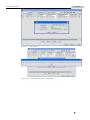
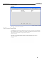
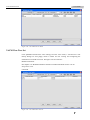
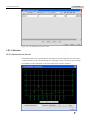
1
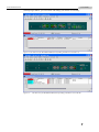
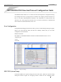
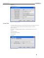
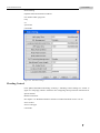
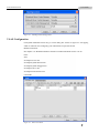
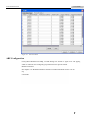
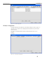
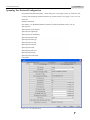
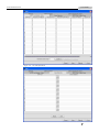
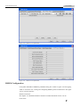
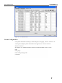
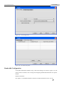
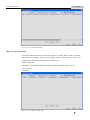
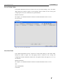
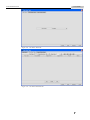
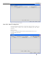
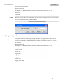
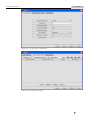
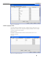
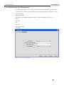
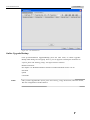
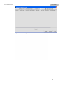
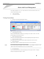
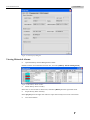
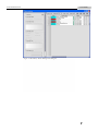
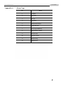
www.raisecom.com ISCOM2826 EMS User Manual RC-A083-V30-050829-EN Legal Notices Raisecom Technology Co., Ltd makes no warranty of any kind with regard to this manual, including, but not limited to, the implied warranties of merchantability and fitness for a particular purpose. Raisecom Technology Co., Ltd shall not be held liable for errors contained herein or direct, indirect, special, incidental or consequential damages in connection with the furnishing, performance, or use of this material. Warranty A copy of the specific warranty terms applicable to your Raisecom product and replacement parts can be obtained from Service Office. Restricted Rights Legend All rights are reserved. No part of this document may be photocopied, reproduced, or translated to another language without the prior written consent of Raisecom Technology Co., Ltd. The information contained in this document is subject to change without notice. Copyright Notices Copyright ©2006 Raisecom. All rights reserved. No part of this publication may be excerpted, reproduced, translated or utilized in any form or by any means, electronic or mechanical, including photocopying and microfilm, without permission in Writing from Raisecom Technology Co., Ltd. Trademark Notices is the trademark of Raisecom Technology Co., Ltd. Java™ is a U.S. trademark of Sun Microsystems, Inc. Microsoft® is a U.S. registered trademark of Microsoft Corporation. Windows NT® is a U.S. registered trademark of Microsoft Corporation. Windows® 2000 is a U.S. registered trademark of Microsoft Corporation. Windows® XP is a U.S. registered trademark of Microsoft Corporation. Windows® and MS Windows® are U.S. registered trademarks of Microsoft Corporation. Contact Information Technical Assistance Center The Raisecom TAC is available to all customers who need technical assistance with a Raisecom product, technology, or, solution. You can communicate with us through the following methods: Add: 1120, Haitai Tower, 229 Fourth North Loop Middle Road, Haidian District, Beijing 100083 Tel: +86-10-82883305 (International Department) Fax: +86-10-82885200, +86-10-82884411 World Wide Web You can access the most current Raisecom product information on the World Wide Web at the following URL: http://www.raisecom.com Feedback Comments and questions about how the NView iEMS system software works are welcomed. Please review the FAQ in the related manual, and if your question is not covered, send email by using the following web page: http://www.raisecom.com/en/xcontactus/contactus.htm. If you have comments on the NView iEMS specification, instead of the web page above, please send comments to: [email protected] We hope to hear from you! CONTENTS Overview ------------------------------------------------------------------------------------------------------------------------------------1 Compliance----------------------------------------------------------------------------------------------------------------------------------- 1 Function Characteristics ------------------------------------------------------------------------------------------------------------------- 1 ISCOM2826 EMS Function/Protocol Configuration Guide -------------------------------------------------------------------------3 Port Configuration -------------------------------------------------------------------------------------------------------------------------- 3 RFC1213 System Group ------------------------------------------------------------------------------------------------------------------- 3 System Time --------------------------------------------------------------------------------------------------------------------------------- 4 Switch Information ------------------------------------------------------------------------------------------------------------------------- 5 Switch Configuration ----------------------------------------------------------------------------------------------------------------------- 5 Flooding Control ---------------------------------------------------------------------------------------------------------------------------- 6 VLAN Configuration ----------------------------------------------------------------------------------------------------------------------- 7 ARP Configuration ------------------------------------------------------------------------------------------------------------------------- 8 IP Subnet Configuration ------------------------------------------------------------------------------------------------------------------- 9 Spanning Tree Protocol Configuration ------------------------------------------------------------------------------------------------- 10 DHCP Configuration ---------------------------------------------------------------------------------------------------------------------- 13 RMON Configuration --------------------------------------------------------------------------------------------------------------------- 15 Trunk Configuration ----------------------------------------------------------------------------------------------------------------------- 17 Bandwidth Configuration ----------------------------------------------------------------------------------------------------------------- 18 Access Control List ------------------------------------------------------------------------------------------------------------------------ 19 IP Access Control List ------------------------------------------------------------------------------------------------------------- 19 MAC Access Control List--------------------------------------------------------------------------------------------------------- 20 User ACL Rule Table -------------------------------------------------------------------------------------------------------------- 21 Filter Rule Table -------------------------------------------------------------------------------------------------------------------- 21 Static MAC Address Configuration----------------------------------------------------------------------------------------------------- 23 Port Mirroring Configuration ------------------------------------------------------------------------------------------------------------ 24 IGMP SNOOPING Configuration ------------------------------------------------------------------------------------------------------ 24 MVR Configuration ----------------------------------------------------------------------------------------------------------------------- 25 IGMP Filter Configuration --------------------------------------------------------------------------------------------------------------- 27 QoS Configuration ------------------------------------------------------------------------------------------------------------------------- 29 QoS Configuration ----------------------------------------------------------------------------------------------------------------- 29 QoS Traffic Class------------------------------------------------------------------------------------------------------------------- 30 QoS Mapping ----------------------------------------------------------------------------------------------------------------------- 34 QoS Queue -------------------------------------------------------------------------------------------------------------------------- 36 SNTP Client Configuration -------------------------------------------------------------------------------------------------------------- 38 SysLog Configuration --------------------------------------------------------------------------------------------------------------------- 39 SNMP Community Table ----------------------------------------------------------------------------------------------------------------- 41 User Authentication And Management------------------------------------------------------------------------------------------------- 42 Cluster Management Protocol ----------------------------------------------------------------------------------------------------------- 43 Neighbor Discovery Protocol ------------------------------------------------------------------------------------------------------------ 44 Topology Discovery Protocol ------------------------------------------------------------------------------------------------------------ 46 SNMP Engine ID--------------------------------------------------------------------------------------------------------------------------- 48 USM Statistical Information ------------------------------------------------------------------------------------------------------------- 48 USM Table ---------------------------------------------------------------------------------------------------------------------------------- 49 VACM Security To Group Table -------------------------------------------------------------------------------------------------------- 51 VACM Access Control Table ------------------------------------------------------------------------------------------------------------ 52 VACM View Tree Set --------------------------------------------------------------------------------------------------------------------- 53 SNMP Target Address Table ------------------------------------------------------------------------------------------------------------- 54 SNMP Target Parameters Table --------------------------------------------------------------------------------------------------------- 54 CPU Utilization ---------------------------------------------------------------------------------------------------------------------------- 55 CPU Utilization In One Second -------------------------------------------------------------------------------------------------- 55 CPU Utilization In One Minute -------------------------------------------------------------------------------------------------- 56 Operation Notification -------------------------------------------------------------------------------------------------------------------- 56 Rebooting The Device -------------------------------------------------------------------------------------------------------------------- 56 Saving Current Configuration ----------------------------------------------------------------------------------------------------------- 57 Deleting Current Configuration --------------------------------------------------------------------------------------------------------- 57 Schedule List -------------------------------------------------------------------------------------------------------------------------------- 58 Online Upgrade/Backup ------------------------------------------------------------------------------------------------------------------ 59 Alarm And Event Management -------------------------------------------------------------------------------------------------------- 61 Viewing Current Alarm ------------------------------------------------------------------------------------------------------------------- 61 Viewing Historical Alarms --------------------------------------------------------------------------------------------------------------- 62 Appendix A Alarm Type ----------------------------------------------------------------------------------------------------------- 65 Appendix B Expansion Card Type--------------------------------------------------------------------------------------------------- 66 www.raisecom.com User Manual Overview This chapter describes compliance and basic functions of ISCOM2826 EMS, and consists of the following sections: Compliance Function characteristics Compliance Support for the following MIB standards: RFC1213 RFC1271 RFC1493 RFC1724 RFC1757 RFC1850 RFC1907 RFC2233 RFC2571 RFC2572 RFC2573N RFC2573T RFC2574 RFC2575 RFC2618 RFC2620 RFC2665 RFC2674P RFC2674Q Function Characteristics ISCOM2826 EMS (Element Management System) provides management of ISCOM2826 Switch through Simple Network Management Protocol (SNMP). The device view generated by the EMS is identical with appearance of the real device, so it could truly reflect current status of the Switch. Through prior installation of NView iEMS (or NView NNM) network management platform, ISCOM2826 EMS, together with configuration of relevant parameters like SNMP information 1 www.raisecom.com User Manual and Trap target address, you can monitor and manage your Switch conveniently. Figure 1-1 The main view for ISCOM2826 EMS (Corresponding to hardware version Rev.A) Figure 1-2 The main view for ISCOM2826 EMS (Corresponding to hardware version Rev.B) 2 www.raisecom.com User Manual ISCOM2826 EMS Function/Protocol Configuration Guide ISCOM2826 EMS enables user to launch relevant function/protocol configuration dialog box through main menu or popup menu as available. This chapter provides instruction on how to use these function/protocol interfaces. For information on each protocol and function’s role, value range and restriction rule, see relevant commands in “RAISECOM Series Switch Command Notebook Version 3.0”. Port Configuration Click [Port\Port Settings] from the main menu, you’ll see a Port Settings dialog box popup. Select a row from the Port table, and click the <Modify> button, then you can make configuration for the selection. Related commands: See chapter 3 of “RAISECOM Series Switch Command Notebook Version 3.0” for “interface port” “pvid” command. Figure 2-1 The port settings RFC1213 System Group Click [Device\RFC1213 System Group] from the main menu, a RFC1213 System Group dialog box similar to figure 2-2 will popup, which is useful for user configuring basic 3 www.raisecom.com User Manual information. Related commands: Figure 2-2 C1213 System Group System Time Click [Main Menu\Device\System Time] to launch the System Time dialog box. From it, you can view and configure system time for the Switch. See figure 2-3 and 2-4. Related commands: See chapter 3 of “RAISECOM Series Switch Command Notebook Version 3.0” for clock set clock summer-time clock summer-time recurring clock timezone commands. Figure 2-3 The system time 4 www.raisecom.com User Manual Figure 2-4 The summer time Switch Information Click [Main Menu\Device\Switch Info], a Switch Info dialog box presenting the basic information on the Switch will popup. Figure 2-5 The Switch information Switch Configuration Click [Main Menu\Device\Device Settings], a Device Setting dialog box will popup for user configuring the global information for the Switch. Related commands: See chapter 3 of “RAISECOM Series Switch Command Notebook Version 3.0” for arp aging-time 5 www.raisecom.com User Manual dlf-forwarding loopback-detection destination-address mac-address-table aging-time relay svl system mtu commands. Figure 2-6 The device settings Flooding Control Click [Main Menu\Device\Flooding Control], a Flooding Control dialog box similar to figure 2-7 will popup, which is useful for user configuring storm prevention information for specific Switch. Related commands: See chapter 3 of “RAISECOM Series Switch Command Notebook Version 3.0” for storm-control storm-control pps commands. 6 www.raisecom.com User Manual Figure 2-7 Flooding Control Configuration VLAN Configuration Click [Main Menu\Device\VLAN], a VLAN dialog box similar to figure 2-8 will popup, which is useful for user configuring vlan information for specific Switch. Related commands: See chapter 3 of “RAISECOM Series Switch Command Notebook Version 3.0” for name state switchport access vlan switchport hybrid allowed vlan switchport hybrid untagged vlan switchport native vlan switchport trunk allowed vlan commands. Figure 2-8 Static VLAN Table 7 www.raisecom.com User Manual Figure 2-9 The VLAN Table ARP Configuration Click [Main Menu\Device\ARP], an ARP dialog box similar to figure 2-10 will popup, which is useful for user configuring arp information for specific Switch. Related command: See chapter 3 of “RAISECOM Series Switch Command Notebook Version 3.0” for arp commands. 8 www.raisecom.com User Manual Figure 2-10 The ARP Configuration IP Subnet Configuration Click [Main Menu\Device\IP Addresses], an IP Addresses dialog box similar to figure 2-11 will popup, which is useful for user configuring IP subnet information for specific Switch. Related command: See chapter 3 of “RAISECOM Series Switch Command Notebook Version 3.0” for ip address commands. Figure 2-11 The IP Subnet Configuration 9 www.raisecom.com User Manual Spanning Tree Protocol Configuration Click [Main Menu\Device\STP], a STP dialog box will popup, which is useful for user viewing and configuring STP information for specific Switch. See figure 2-12 to 2-17 for reference. Related commands: See chapter 3 of “RAISECOM Series Switch Command Notebook Version 3.0” for spanning-tree spanning-tree clear statistics spanning-tree edged-port spanning-tree forward-delay spanning-tree hello-time spanning-tree link-type spanning-tree max-age spanning-tree mcheck spanning-tree mode spanning-tree path-cost spanning-tree priority spanning-tree transit-limit commands. Figure 2-12 The STP information 10 www.raisecom.com User Manual Figure 2-13 The STP information Figure 2-14 The STP information 11 www.raisecom.com User Manual Figure 2-15 The STP information 12 www.raisecom.com User Manual Figure 2-16 The STP information Figure 2-17 The STP information DHCP Configuration Click [Main Menu\Device\DHCP], a DHCP Server dialog box will popup, which is useful for user viewing and configuring DHCP Server information. See figure 2-18 to 2-21 for reference. Related commands: See chapter 3 of “RAISECOM Series Switch Command Notebook Version 3.0” for dhcp-server active dhcp-server default-lease dhcp-server enable dhcp-server ip-pool dhcp-server max-lease dhcp-server min-lease dhcp-server relay-ip commands. 13 www.raisecom.com User Manual Figure 2-18 DHCP Server Information Figure 2-19 DHCP Server Information 14 www.raisecom.com User Manual Figure 2-20 DHCP Server Information Figure 2-21 DHCP Server Information RMON Configuration Click [Main Menu\Device\RMON], a RMON dialog box similar to figure 2-22 will popup, which is useful for user viewing and configuring RMON protocol information. See figure 2-22 to 2-24 for reference. Related commands: See chapter 3 of “RAISECOM Series Switch Command Notebook Version 3.0” for rmon alarm 15 www.raisecom.com User Manual rmon event rmon history rmon statistic commands. Figure 2-22 The Event Table Figure 2-23 The Alarm Table 16 www.raisecom.com User Manual Figure 2-24 The Statistics Table Trunk Configuration Click [Main Menu\Device\Trunk], a Trunk dialog box will popup, which is useful for user viewing and configuring Trunk information. See figure 2-25 to 2-26 for reference. Related commands: See chapter 3 of “RAISECOM Series Switch Command Notebook Version 3.0” for trunk trunk group trunk loading-sharing mode commands. 17 www.raisecom.com User Manual Figure 2-25 Trunk Configuration Figure 2-26 The Trunk Group Table Bandwidth Configuration Click [Main Menu\Device\Rate Limit], a Rate Limit dialog box similar to figure 2-27 will popup, which is useful for user viewing and configuring bandwidth information for specific Switch. Related commands: See chapter 3 of “RAISECOM Series Switch Command Notebook Version 3.0” for 18 www.raisecom.com User Manual rate-limit port-list commands. Figure 2-27 The Rate Limit dialog box Access Control List IP Access Control List Click [Main Menu\Device\Access Control List\IP ACL Rule Table], an IP ACL Rule Table dialog box similar to figure 2-28 will popup, which is useful for user viewing and configuring the IP ACL information for specific Switch. Related commands: See chapter 3 of “RAISECOM Series Switch Command Notebook Version 3.0” for ip-access-list commands. 19 www.raisecom.com User Manual Figure 2-28 The IP ACL Rule Table MAC Access Control List Click [Main Menu\Device\Access Control List \MAC ACL Rule Table], a MAC ACL Rule Table dialog box similar to figure 2-29 will popup, which is useful for user viewing and configuring the MAC ACL information for specific Switch. Related commands: See chapter 3 of “RAISECOM Series Switch Command Notebook Version 3.0” for mac-access-list commands. Figure 2-29 The MAC ACL Rule Table 20 www.raisecom.com User Manual User ACL Rule Table Click [Main Menu\Device\Access Control List \User ACL Rule Table], a User ACL Rule Table dialog box similar to figure 2-30 will popup, which is useful for user viewing and configuring the User ACL information for specific Switch. Related commands: See chapter 3 of “RAISECOM Series Switch Command Notebook Version 3.0” for user-access-list commands. Figure 2-30 The User ACL Rule Table Filter Rule Table Click [Main Menu\Device\Access Control List \Filter Rule Table], a Filter Rule Table dialog box similar to figure 2-31 will popup, which is useful for user viewing and configuring the filter information within ACL for specific Switch. See figure 2-31 to 2-33 for reference. Related commands: See chapter 3 of “RAISECOM Series Switch Command Notebook Version 3.0” for filter filter enable|disable commands. 21 www.raisecom.com User Manual Figure 2-31 The Filter Action Tab Figure 2-32 The Filter Rule Table Tab 22 www.raisecom.com User Manual Figure 2-33 The Layer-3 Filter Table Tab Static MAC Address Configuration Click [Main Menu\Device\Static MAC], a Static MAC dialog box similar to figure 2-34 will popup, which is useful for user viewing and configuring static MAC address information. Related commands: See chapter 3 of “RAISECOM Series Switch Command Notebook Version 3.0” for mac-address-table static unicast commands. 23 www.raisecom.com User Manual Figure 2-34 The Static MAC Address configuration Port Mirroring Configuration Click [Main Menu\Device\Port Mirroring], a port mirroring configuration dialog box similar to figure 2-35 will popup, which is useful for user viewing and configuring port mirroring information for specific Switch. Related commands: See chapter 3 of “RAISECOM Series Switch Command Notebook Version 3.0” for mirror mirror monitor-port mirror source-port-list commands. Figure 2-35 The Port Mirroring configuration IGMP SNOOPING Configuration Click [Main Menu\Device\IGMP Snooping], an IGMP Snooping dialog box similar to figure 2-36 will popup, which is useful for user viewing and configuring IGMP Snooping information for specific Switch. Related commands: See chapter 3 of “RAISECOM Series Switch Command Notebook Version 3.0” for ip igmp snooping ip igmp snooping immediate-leave ip igmp snooping mrouter ip igmp snooping vlan ip igmp snooping vlan vlanlist immediate-leave ip igmp snooping timeout commands. 24 www.raisecom.com User Manual Figure 2-36 The IGMP SNOOPING configuration Figure 2-37 The Lay-2 Multicast Table MVR Configuration Click [Main Menu\Device\MVR Configuration], an MVR Configuration dialog box will popup, which is useful for user viewing and configuring MVR information for specific Switch. See figure 2-38 to 2-41 for reference. Related commands: See chapter 3 of “RAISECOM Series Switch Command Notebook Version 3.0” for mvr disable 25 www.raisecom.com User Manual mvr enable mvr group mvr mode mvr timeout mvr vlan commands. Figure 2-38 The MVR Configuration Figure 2-39 The MVR Multicast Group Table 26 www.raisecom.com User Manual Figure 2-40 The MVR IF Configuration Table Figure 2-41 The MVR IF Members Table IGMP Filter Configuration Click [Main Menu\Device\IGMP Filter Configuration], an IGMP Filter Configuration dialog box will popup, which is useful for user viewing and configuring IGMP Filter information for specific Switch. See figure 2-42 to 2-44 for reference. Related commands: See chapter 3 of “RAISECOM Series Switch Command Notebook Version 3.0” for ip igmp filter 27 www.raisecom.com User Manual ip igmp profile commands. Figure 2-42 The IGMP Filter configuration Figure 2-43 The IGMP Profile Table 28 www.raisecom.com User Manual Figure 2-44 The IGMP Filter IF Table QoS Configuration QoS Configuration Click [Main Menu\Device\QoS\QoS Configuration], an QoS Configuration dialog box will popup, which is useful for user viewing and configuring information regarding global QoS and QoS port for specific Switch. See figure 2-45 and 2-46 for reference. Related commands: See chapter 3 of “RAISECOM Series Switch Command Notebook Version 3.0” for mls qos mls qos default-cos mls qos default-dscp mls qos dscp-mutation commands. 29 www.raisecom.com User Manual Figure 2-45 The global QoS configuration Figure 2-46 The QoS port configuration QoS Traffic Class Click [Main Menu\Device\QoS\QoS Traffic Class], a QoS Traffic Class dialog box will popup, which is useful for user viewing and configuring information regarding QoS port, 30 www.raisecom.com User Manual Policy Map, Match Statement, Policer and Action. See figure 2-47 and 2-52 for reference. Related commands: See chapter 3 of “RAISECOM Series Switch Command Notebook Version 3.0” for class-map description(class-map) description(policy-map) match mls qos {aggregate-policer |class-policer | single-policer } police policy-map commands. Figure 2-47 The QoS Service Policy Table 31 www.raisecom.com User Manual Figure 2-48 The QoS Policy Map information Figure 2-49 The QoS Class Map information 32 www.raisecom.com User Manual Figure 2-50 The QoS Match Statement information Figure 2-51 The QoS Policer information 33 www.raisecom.com User Manual Figure 2-52 The QoS Action information QoS Mapping Click [Main Menu\Device\QoS\QoS Mapping], a QoS Mapping dialog box will popup, which is useful for user viewing and configuring information regarding: DSCP Mutation, Mapping from CoS to DSCP, Mapping from ToS to DSCP, and Mapping from DSCP to CoS . See figure 2-53 and 2-56 for reference. Related commands: See chapter 3 of “RAISECOM Series Switch Command Notebook Version 3.0” for mls qos map cos-dscp mls qos map dscp-cos mls qos map dscp-mutation mls qos map ip-prec-dscp commands. 34 www.raisecom.com User Manual Figure 2-53 DSCP Mutation Configuration Figure 2-54 Mapping from CoS to DSCP 35 www.raisecom.com User Manual Figure 2-55 Mapping from ToS to DSCP Figure 2-56 Mapping from DSCP to CoS QoS Queue Click [Main Menu\Device\QoS\QoS Queue], a QoS Queue dialog box will popup, which is 36 www.raisecom.com User Manual useful for user viewing and configuring information regarding QoS queue. See figure 2-57 and 2-59 for reference. Related commands: See chapter 3 of “RAISECOM Series Switch Command Notebook Version 3.0” for queue bounded-delay queue cos-map queue strict-priority queue wrr-weight commands. Figure 2-57 Configure the QoS Queue 37 www.raisecom.com User Manual Figure 2-58 The QoS Queue Information Figure 2-59 The CoS to Egress table SNTP Client Configuration Click [Main Menu\Device\SNTP Client], a SNTP Client dialog box similar to figure 2-60 will popup, which is useful for user viewing and configuring SNTP (Simple Network Time 38 www.raisecom.com User Manual Protocol) Client information. Related commands: See chapter 3 of “RAISECOM Series Switch Command Notebook Version 3.0” for sntp server commands. NOTE: After you have set address of SNTP Client, click the <Save> button. The Switch will synchronize the time immediately from the configured address. Figure 2-60 The SNTP Client Configuration SysLog Configuration Click [Main Menu\Device\Syslog], a Syslog dialog box will popup, which is useful for user viewing and configuring SYSLOG information for specific Switch. See figure 2-61 to 2-63 for reference. Related commands: See chapter 3 of “RAISECOM Series Switch Command Notebook Version 3.0” for debug logging console logging file logging host logging monitor logging on logging rate logging time-stamp commands. 39 www.raisecom.com User Manual Figure 2-61 The SysLog Server Information Figure 2-62 The SysLog Server Table 40 www.raisecom.com User Manual Figure 2-63 The Debug Table SNMP Community Table Click [Main Menu\Device\SNMP Community], a SNMP Community Table dialog box will popup, which is useful for user viewing and configuring information related to SNMP Community. See figure 2-64 for reference. Related commands: See chapter 3 of “RAISECOM Series Switch Command Notebook Version 3.0” for snmp-server community commands. Figure 2-64 The SNMP Community Table 41 www.raisecom.com User Manual User Authentication And Management Click [Main Menu\Device\User Config], a user configuration dialog box will popup, which is useful for user accessing and configuring the account information. See figure 2-65 and 2-66 for reference. Related commands: See chapter 3 of “RAISECOM Series Switch Command Notebook Version 3.0” for radius radius-key user user login user name privilege commands. Figure 2-65 The User Configuration 42 www.raisecom.com User Manual Figure 2-66 The User Information Cluster Management Protocol Click [Cluster\RCMP] from the main menu, a RCMP dialog box will popup, which is useful for user viewing and configuring information related to cluster management protocol. See figure 2-67 and 2-68 for reference. Related commands: See chapter 3 of “RAISECOM Series Switch Command Notebook Version 3.0” for cluster cluster-autoactive cluster-autoactive commander-mac commands. 43 www.raisecom.com User Manual Figure 2-67 The RCMP Set Figure 2-68 The RCMP Member Table Neighbor Discovery Protocol Click [Cluster\RNDP] from the main menu, a RNDP dialog box will popup, which is useful for user viewing and configuring information related to RNDP (Raisecom Neighbor Discovery Protocol). See figure 2-69 and 2-71 for reference. Related commands: 44 www.raisecom.com User Manual See chapter 3 of “RAISECOM Series Switch Command Notebook Version 3.0” for rndp commands. Figure 2-69 Figure 2-70 The RNDP Protocol The RNDP Interface Table 45 www.raisecom.com User Manual Figure 2-71 The RNDP Discovery Table Topology Discovery Protocol Click [Cluster\RTDP] from the main menu, a RTDP dialog box will popup, which is useful for user viewing and configuring information related to RTDP (Raisecom Topology Discovery Protocol). See figure 2-72 and 2-74 for reference. Related commands: See chapter 3 of “RAISECOM Series Switch Command Notebook Version 3.0” for rtdp rtdp max-hop commands. 46 www.raisecom.com User Manual Figure 2-72 The RTDP Protocol Figure 2-73 The RTDP Device Discovery Table 47 www.raisecom.com User Manual Figure 2-74 The RTDP Relationship Table SNMP Engine ID Click [SNMPv3\SNMP Engine ID] from the main menu, a SNMP Engine ID dialog box will popup, which is useful for user viewing the information on SNMP Engine ID. See figure 2-75 for reference. Figure 2-75 The SNMP Engine ID USM Statistical Information Click [SNMPv3\USM Statistics] from the main menu, a USM Statistics dialog box will popup, which is useful for user viewing the results on USM statistic. See figure 2-76 for reference. 48 www.raisecom.com User Manual Figure 2-76 The USM Statistics USM Table Click [SNMPv3\USM User Table] from the main menu, a USM User Table dialog box will popup, which is useful for user viewing and configuring the information on USM user. Related commands: See chapter 3 of “RAISECOM Series Switch Command Notebook Version 3.0” for snmp-server user commands. Note: Add: Input appropriate information in the User Name and User Clone From fields, where the “User Clone From” information refers to the user of “Active” state existing in USM User Table. You can input these information by clicking the [Select] button. If “User Clone From” points to a user whose “Authentication Protocol” setting is configured as “No Authentication”, then the add operation finishes successfully, and state of the newly added user is “active”; otherwise the state of this user is configured as “NotReady”. To put this user’s state in “active”, you have to change his/her Authentication Key or alter “Authentication Protocol” to “No Authentication”. See figure 2-77 and 2-78. Modify: You can modify Authentication Key or “Authentication Protocol” for a user, where “Authentication Protocol” can only be changed to “No Authentication”. When this modification made for a user with “NotReady” state successes, the user’s state will change to “active”. 49 www.raisecom.com User Manual Figure 2-77 Add USM user Figure 2-78 The Prompt message when creating USM user 50 www.raisecom.com User Manual Figure 2-79 Modify User Information Figure 2-80 The prompt message for successful modification VACM Security To Group Table Click [SNMPv3\VACM Security To Group Table] from the main menu, a VACM Security To Group Table dialog box will popup, which is useful for user viewing and configuring the information regarding mapping relationship from user to access group. See figure 2-81 for reference. Related commands: Related commands: See chapter 3 of “RAISECOM Series Switch Command Notebook Version 3.0” for 51 www.raisecom.com User Manual snmp-server group commands. Figure 2-81 VACM Security To Group Table VACM Access Control Table Click [SNMPv3\VACM Access Table] from the main menu, a VACM Access Table dialog box will popup, which is useful for user viewing and configuring the information within VACM Access Control Table. See figure 2-82 for reference. Related commands: See chapter 3 of “RAISECOM Series Switch Command Notebook Version 3.0” for snmp-server access command. 52 www.raisecom.com User Manual Figure 2-82 The VACM Access Table VACM View Tree Set Click [SNMPv3\VACM View Tree Family] from the main menu, a VACM View Tree Family dialog box will popup, which is useful for user viewing and configuring the information on VACM View Tree. See figure 2-83 for reference. Related commands: See chapter 3 of “RAISECOM Series Switch Command Notebook Version 3.0” for snmp-server view command. Figure 2-83 The VACM View Tree Set 53 www.raisecom.com User Manual SNMP Target Address Table Click [SNMPv3\SNMP Target Address Table] from the main menu, a SNMP Target Address Table dialog box will popup, which is useful for user viewing and configuring the information on address of SNMP target. See figure 2-84 for reference. Related commands: See chapter 3 of “RAISECOM Series Switch Command Notebook Version 3.0” for snmp-server host commands. Figure 2-84 The SNMP Target Address Table SNMP Target Parameters Table Click [SNMPv3\SNMP Target Parameters Table] from the main menu, a SNMP Target Parameters Table dialog box will popup, which is useful for user viewing and configuring the parameters of SNMP target. See figure 2-85 for reference. 54 www.raisecom.com User Manual Figure 2-85 The SNMP Target Parameters Table CPU Utilization CPU Utilization In One Second Click [Performance\CPU Utilization\CPU Utilization In One Second] from the main menu, a CPU Utilization In One Second dialog box will popup, which is useful for user viewing the condition of CPU utilization in one second. See figure 2-86 for reference. 55 www.raisecom.com User Manual Figure 2-86 CPU Utilization In One Second CPU Utilization In One Minute Click [Performance\CPU Utilization\CPU Utilization In One Minute] from the main menu, a CPU Utilization In One Minute dialog box will popup, which is useful for user viewing the utilization condition of CPU in one minute. See figure 2-87 for reference. Figure 2-87 CPU Utilization In One Minute Operation Notification Click [Command\Operating Notification] from the main menu, to set whether to send notification when save or erase the configuration. See figure 2-88 for reference. Figure 2-88 The Operating Notification Rebooting The Device Click [Command\Reboot] from the main menu, to trigger the command to reboot the Switch. See figure 2-89 for reference. Related commands: 56 www.raisecom.com User Manual See chapter 3 of “RAISECOM Series Switch Command Notebook Version 3.0” for reboot commands. Figure 2-89 The confirm dialog box for rebooting device Saving Current Configuration Click [Command\Write] from the main menu, to save current configuration. See figure 2-90 for reference. Related commands: See chapter 3 of “RAISECOM Series Switch Command Notebook Version 3.0” for write commands. Figure 2-90 The Confirm dialog box for saving configuration Deleting Current Configuration Click [Command\Erase] from the main menu, to delete current configuration. See figure 2-91 for reference. Related commands: See chapter 3 of “RAISECOM Series Switch Command Notebook Version 3.0” for erase commands. Figure 2-91 The Confirm dialog box for deleting configuration 57 www.raisecom.com User Manual Schedule List Click [Command\Schedule List] from the main menu, a Schedule List dialog box will popup. From it, you can view the information regarding Schedule list. See figure 2-92 and 2-93 for reference. Related commands: See chapter 3 of “RAISECOM Series Switch Command Notebook Version 3.0” for show schedule-list commands. Figure 2-92 The Schedule List 58 www.raisecom.com User Manual Figure 2-93 The Schedule List Online Upgrade/Backup Click [Command\Online Upgrade/Backup] from the main menu, an Online Upgrade/ Backup Table dialog box will popup. From it, you can upgrade or backup the documents of “System_boot” and “Startup_config”. See figure 2-94 for reference. Related commands: See chapter 3 of “RAISECOM Series Switch Command Notebook Version 3.0” for download upload commands. NOTE: After you have upgraded the “System_boot” and “Startup_config” documents, reboot the Switch, then the configuration will take effective. 59 www.raisecom.com User Manual Figure 2-94 The Online Upgrade/Backup Table 60 www.raisecom.com User Manual Alarm And Event Management This chapter introduces how to view and maintain the current and historical alarm, and consists of the following sections: View Current Alarm View Historical Alarm Viewing Current Alarm ¾ Open the Current Alarms Management window Double click the NView Platform Function Tree, and select [Current Alarms Management]. Figure 3-1 The Current Alarms window ¾ Acknowledge alarm record(s) Select a record with state of “Newcome” presenting in the “Status” column, and select [Acknowledge] from the right click menu. ¾ Delete current alarm record(s) Select one or more records in the Alarm List, and select [Delete] from the right click menu. ¾ Export current alarm record(s) Select [Export] from the right click menu to export record(s) into a Text or Excel file. ¾ Filter current alarms Input filtration conditions - IP address range and severity level, then click [Filter]. NOTE: The IP Address Range field supports asterisk wildcard “*”. For example, “192.168.1.*”, the address range of asterisk wildcard here can be set as “Start IP Address”. ¾ View Alarm Details Click a record in the Alarm List, and select [Property] from the right click menu. A Property dialog box will popup as the figure 5-2 shows. 61 www.raisecom.com User Manual Figure 3-2 The Property dialog box Viewing Historical Alarms ¾ Open the History Alarms Management window Double click the Nview Platform function tree, and select [History Alarms Management]. Figure 3-3 The History Alarms window ¾ Delete history alarm record(s) Select one or more records in Alarm List, and select [Delete] from the right click menu. ¾ Export history alarm record(s) Select [Export] from the right click menu to export the record(s) into a Text or Excel file. ¾ View alarm details 62 www.raisecom.com User Manual Figure 3-4 The Property dialog box ¾ Query history alarms Select [Query] from the right click menu, the Query Condition panel will appear. It enables query on history alarms by condition(s) like device node, time range, alarm type and alarm level. 63 www.raisecom.com User Manual Figure 3-5 The History Alarms Management dialog box 64 www.raisecom.com Appendix A User Manual Alarm Type No. Alarm 1 Cold Start 2 Warm Start 3 Link Up 4 Link Down 5 Authentication Failure 6 Config Operation 7 Online Upgrade/Backup 8 RTDP Topology Change 9 STP New Root 10 Topology Change 11 RMON Falling 12 RMON Rising 65 www.raisecom.com Appendix B User Manual Expansion Card Type Illustration Model SC200-FE-S1 Description Single-Optical Interface Hardware Version Rev.B 100M Expansion Module SC200-GE-X Single-Optical Rev.B Interface 1000M Expansion Module SC200-GE-T Single-Electronic Rev.B Interface 1000M Expansion Module 66 Add: 812 Haitai Tower, 229 North Fourth Loop Middle Road, Haidian District, Beijing, 100083 T:(8610)-82883305 F: 8610)-82883305 Http://www.raisecom.com [email protected]