1
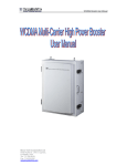
Mobile Signal Booster User Manual User Manual Preface We appreciate that you selecting our signal amplifier. The detailed User Manual is attached to this machine so that you can get familiar to operate it as soon as possible, from which you will get the information of product introduction, operation instructions, system settings and safety precautions, etc. -2- User Manual Contents 1. Purpose 2. Technical features 3. Application 4. Technical specifications 5. System configuration 6. Operation instructions 7. 6.1. Descriptions of the overall dimension of the equipment 6.2. Instructions on installation 6.3. Debugging and commissioning 6.4. System maintenance Descriptions on maintenance 7.1. Faults and failures 7.2. Troubleshooting -3- User Manual Safety Warning Users must follow the below principles: 1 Repeater should follow system requirement of communication equipment, assure good groundings and lightning protection. 2 The power supply voltage of repeater should meet the standards of security requirement; any repeater-operator can operate only after cutting power in advance. Only the professional can operate electrified. 3 Do not dismantle machine, maintain or displace accessories by yourself, because in this way, the equipment may be damaged or even get an electric shock. 4 Do not open the repeater; touch the module of repeater, even not to open the cover of module to touch the electronic component, the components will be damaged due to electrostatic 5 Please keep away from heating-equipment, because the repeater will dissipate heat when working. And do not cover repeater with anything that influences heat-dissipation. 1. Purpose -4- User Manual As the domestic mobile communication industry develops rapidly, the amount of mobile communications users increases so steadily that the cell planning gets smaller and smaller while the base station positions get lower and lower. On the other hand, as city construction develops, more and more high-rise buildings are set up constantly, based on the shadow effect of the radio propagation, the mobile communications may get a signal blind spot behind or between the buildings. Moreover, in order to avoid interference from adjacent districts, the main lobe of the antenna radiation orientation of the cell mobile communication base station in construction has a bigger down-tilt obliquity, thus the signals usually can not be received effectively in the high and medium parts of the high rise buildings. Furthermore, due to the shield effect to electro-magnetic waves caused by buildings, the mobile communication signals cannot be received in tunnels, subways, underground stores, entertainment complex, parking fields, hotels, office buildings and other large-size and closed buildings. Signal amplifier is an effective device that makes up the insufficient base station coverage in the mobile network, enlarges the coverage area of the base station and fills in the blind spots, which adopts double-ended duplex design and external power supply with advantages of convenient mounting and high reliability. The bandwidth of the signal amplifier may cover GSM, CDMA, DCS,PCS, WCDMA with compatibility between digital -5- User Manual system and analogue system. 2. Technical features High system gains Full duplex and double-end design, external power supply, and convenient installation ALC technology with auto-steady function adopted. Provide power indication and uplink and downlink indications. With the amplified linear power, the intermodulation and spuriousness are suppressed effectively. The reliability conforms to GB6993-86 standards. The electromagnetic compatibility conforms to ETS300 609-4 standards -6- User Manual 3. Application. This product is suitable for operation of mobile phones in a weak signal area! -7- User Manual 4. Technical specifications Model TE-9102A Frequency range Model TE-9102B 890-915MHz Downlink 935-960MHz TE-9102A-C Frequency range Model TE-9102B-C TE-9102C-C Uplink 824-849MHz Downlink 869-894MHz TE-9102A-I Frequency range TE-9102C Uplink TE-9102B-I TE-9102C-I Uplink 806-824MHz Downlink 851-869MHz Gain Uplink Gp≥55 Gp≥65 Gp≥45 (dB) Downlink Gp≥60 Gp≥70 Gp≥50 MGC≥30dB Gain adjustable(only B/B-C/B-i ) Output power ≥20dBm ≥20dBm ≤5dB Pass band ripple I/O impedance 50Ω/N Connector ≤-8dB I/O return loss ≤-8dB Noise figure ≤-40dBc Intermodulation attenuation(Po=13dBm) ≤0.5μs Transmission Ambient Power supply ≥23dBm -10℃~50℃ AC110~240V±10% 45~55Hz Reliability To the GB6993-86 standard Electromagnetic To the ETS300 694-4 standard Function a) Power supply LED enote b) Export power LED enote RF Connector N-Female Size 184mm×107mm×33mm Size(TE-9102B/B-C/B-i) 190mm×107mm×33mm Weight < 1.2 Kg -8- User Manual Model TE-9050 Frequency range TE-9060 Uplink 890-915MHz Downlink Model TE-8050 Frequency range TE-9070 935-960MHz TE-8060 Uplink 824-849MHz Downlink 869-894MHz TE-8070 Gain Uplink Gp≥45 Gp≥55 Gp≥65 (dB) Gp≥50 Gp≥60 Gp≥70 ≥17dBm ≥17dBm ≥20dBm Downlink Output power ≤5dB Pass band ripple (BW-60dB)≤42MHz , (BW-70dB)≤45MHz Guard band rejection I/O impedance 50Ω/N Connector ≤-8dB I/O return loss Noise figure ≤-8dB Intermodulation attenuation(Po=13dBm) ≤-40dBc Transmission ≤0.5μs Ambient Power supply -10℃~50℃ AC110~240V±10% 45~55Hz Reliability To the GB6993-86 standard Electromagnetic To the ETS300 694-4 standard Function a) Power supply LED denote b) Export power LED denote RF Connector N-Female Size 135mm×85mm×28mm Size(TE-90/8070) 150mm×85mm×28mm Weight < 0.8 Kg / (TE-90/8070 <1.2 Kg) -9- User Manual Specification Frequency range Specification Frequency range Specification Frequency range TE-1860 TE-1850 Uplink 1710-1785MHz Downlink 1805-1880MHz TE-1960 TE-1950 Uplink 1850-1910MHz Downlink 1930-1990 MHz TE-3G60 TE-3G50 Uplink 1920-1980MHz Downlink 2110-2170 MHz Gain Uplink Gp≥55 Gp≥45 (dB) Downlink Gp≥60 Gp≥50 ≥17dBm ≥17dBm Output power ≤10dB Pass band ripple I/O impedance 50Ω/N Connector I/O return loss ≤-8dB Noise figure ≤-8dB Intermodulation attenuation (Po=13dBm) ≤-40dBc Transmission ≤0.5μs Ambient Power supply -10℃~50℃ AC110~240V±10% 45~55Hz Reliability To the GB6993-86 standard Electromagnetic To the ETS300 694-4 standard Function a) Power supply LED denote b) Export power LED denote RF Connector N-Female Size 150mm×85mm×28mm Weight < 0.8 Kg - 10 - User Manual Model TE-9102A-D Frequency range Model TE-9102C-D Uplink 1710-1785MHz Downlink 1805-1880MHz TE-9102A-P Frequency range TE-9102C-P Uplink 1850-1910MHz Downlink 1930-1990 MHz Gain Uplink Gp≥55 Gp≥45 (dB) Downlink Gp≥60 Gp≥50 MGC≥30dB Gain adjustable Output power ≥20dBm ≥20dBm ≤10dB Pass band ripple I/O impedance 50Ω/N Connector I/O return loss ≤-8dB Noise figure ≤-8dB ≤-40dBc Intermodulation attenuation (Po=13dBm) ≤0.5μs Transmission Ambient Power supply -10℃~50℃ AC110~240V±10% 45~55Hz Reliability To the GB6993-86 standard Electromagnetic To the ETS300 694-4 standard Function a) Power supply LED denote b) Export power LED denote RF Connector N-Female Size 220mm×107mm×33mm Weight < 1.2 Kg - 11 - User Manual Model TE-9018A Frequency range Gain Uplink (dB) Downlink TE-9018B Uplink 890-915MHz/ 1710-1785MHz Downlink 935-960MHz / 1805-1880MHz GSM Gp≥55 GSM Gp≥65 GSM Gp≥45 DCS Gp≥50 DCS Gp≥55 DCS Gp≥45 GSM Gp≥60 GSM Gp≥70 GSM Gp≥50 DCS Gp≥55 DCS Gp≥60 DCS Gp≥50 MGC≥30dB Gain adjustable Output power TE-9018C ≥20dBm ≥20dBm ≥20dBm ≤10dB Pass band ripple I/O impedance 50Ω/N Connector I/O return loss ≤-8dB Noise figure ≤-8dB Intermodulation ≤-40dBc attenuation (Po=13dBm) ≤0.5μs Transmission Ambient Power supply Reliability Electromagnetic Function -10℃~50℃ AC110~240V±10% 45~55Hz To the GB6993-86 standard To the ETS300 694-4 standard a) Power supply LED denote b) Export power LED denote RF Connector Size N-Female 196mm×136mm×38mm Weight < 2Kg - 12 - User Manual Model TE-8019A Frequency range Gain Uplink (dB) Downlink TE-8019B Uplink 824-849MHz/ 1850-1910MHz Downlink 869-894MHz / 1930-1990MHz CDMA Gp≥55 CDMA Gp≥65 CDMA Gp≥45 PCS Gp≥50 PCS Gp≥55 PCS Gp≥45 CDMA Gp≥60; CDMA Gp≥70 CDMA Gp≥50 PCS Gp≥55 PCS Gp≥60 PCS Gp≥50 MGC≥30dB Gain adjustable Output power ≥20dBm ≥20dBm ≥20dBm ≤10dB Pass band ripple I/O impedance TE-8019C 50Ω/N Connector I/O return loss ≤-8dB Noise figure ≤-8dB Intermodulation ≤-40dBc attenuation (Po=13dBm) ≤0.5μs Transmission Ambient Power supply -10℃~50℃ AC110~240V±10% 45~55Hz Reliability To the GB6993-86 standard Electromagnetic To the ETS300 694-4 standard Function a) Power supply LED denote b) Export power LED denote RF Connector Size N-Female 196mm×136mm×38mm Weight < 2Kg Installation Type Wall Installation - 13 - User Manual Model TE-903G-A Frequency range Gain (dB) TE-903G-B TE-903G-C Uplink 890-915MHz/ 1920-1980MHz Downlink 935-960MHz / 2110-2170MHz Uplink GSM Gp≥55 3G Gp≥50 GSM Gp≥65 3G Gp≥55 GSM Gp≥45 3G Gp≥45 Downlink GSM Gp≥60 3G Gp≥55 GSM Gp≥70 3G Gp≥60 GSM Gp≥50 3G Gp≥50 MGC≥30dB Gain adjustable Output power ≥20dBm ≥20dBm ≤10dB Pass band ripple I/O impedance 50Ω/N Connector I/O return loss ≤-8dB Noise figure ≤-8dB Intermodulation attenuation (Po=13dBm) ≤-40dBc ≤0.5μs Transmission Ambient Power supply Reliability Electromagnetic Function ≥20dBm -10℃~50℃ AC110~240V±10% 45~55Hz To the GB6993-86 standard To the ETS300 694-4 standard a) Power supply LED denote b) Export power LED denote RF Connector N-Female Size 196mm×136mm×38mm Weight < 2Kg - 14 - User Manual 5. System structure A simple signal amplifier system is composed of a host signal amplifier, reverse antenna and in-door covering system. Reverse antenna aims at the reverse base station that requires for expanding the coverage, the BTS Port of the host signal amplifier is connected with reverse antenna and User’s Port is connected with in-door covering system. As shown in the following diagram, firstly, the indoor signals introduced by the signal amplifier are divided into two-way signals by splitters, then each signal is distributed two antennas through a coupler with the power distribution ratio equal to circuit exhaust ratio so as to ensure both of the antennas to obtain equal power (splitter and coupler may can be configured flexibility). It shall be attached importance that at least 15dB of the isolation shall be bigger than the plus between reverse antenna and covering system for meeting the requirements of C/I≥15dB of the GSM/CDMA/DCS/PCS/WCDMA system. Signal amplifier BTS splitter 220V Coupler Coupler - 15 - User Manual System structure diagram 6. Operation instructions 6.1. Descriptions of the overall dimension of the equipment The whole-set shape is shown as follows: ① RF Port BTS Port (Uplink input, Downlink output)connected with reverse antenna facing to the base station. ② RF Port User’s Port (Uplink input, Downlink output)connected with indoor covering system ③ Uplink power indicator light ④ Downlink power indicator light ⑤ Power indicator light ⑥ Power interface - 16 - User Manual ⑦ Adjustable gain Attenuation(dB) 1 2 3 4 5 Uplink 1 2 4 8 16 Downlink 1 2 4 8 16 6.2 Instructions on installation a) Firstly, select an appropriate position to mount. The signal amplifier is better to be mounted close to walls. At the position selected, punch a hole in the wall as shown in the diagram and aim the bolt at the hole. Then fasten and fix with expansion bolts. b) Connect the BTS Port (①in the diagram) with out door reverse antenna through radio frequency cable. In general, the reverse antenna is mounted at a higher position. Yagi antenna and panel antenna may be used. The main lobe of the antenna radiation is oriented towards the base station and the reverse antenna and base station antenna should be visible as possible. c) Connect User’s Port (②in the diagram ) with the ports of indoor covering system or indoor relay antenna. In general, the indoor covering system is composed of several splitters, couplers, expansion amplifiers and antennas and applied as per specific - 17 - User Manual engineering design for the purpose of satisfying the signal covering demands in large area or complicated terrain indoor space. In the case of small area indoor space, the requirements for covering can be satisfied by using single relay antenna with the option of hanging antenna or ceiling antenna. d) Finally, connect the power interface shown as⑥in the diagram to 5V3A power adapter and power on the adapter with 220v AC. The signal amplifier installation is thus completed. e) Omni antenna (Indoor ceiling omni antenna or whip antenna), suitable to installed in the center and radiate all directions; It is better to use a directional panel antenna or Yagi when the coverage shape is long and narrow (corridors, long row of houses in two sides, tunnels or elevators or rural open space) 6.3. Debugging and commissioning 1. Power on with 220V AC at the premise of no fault being found in inspection. The glowing indicator light shown as⑤in the above diagram is means the power supply works normally. 2. If the reverse antenna is mounted correctly, the Downlink power indicator light should be on. In this case, the covering area of the equipment shall be larger than that in the technical specifications. - 18 - User Manual 3. If the required covering area is too large and the Downlink power indicator light is off after powering on, it means that the input power is not sufficient and the position of the reverse antenna should be adjusted to receive more strong downlink signals. 4. When the debug is completed, select more than 20 points in the covering area to test the signal level and talking effect of the mobile phone. It should be ensured that the signal bar shall be fully filled with strong signal in 90% of the covering area, and less than 5% of the covering area can have two signal bars. Meanwhile talking clearly and no interruption occurs. 5. Switch off and then power on, check whether it is normal. Then test with mobile phone, the working state shall remain same as the original. Keep it running for one to two hours around for further test. 6. Recheck the whole system and clean up the working site. 7. Record the work and fill in the Engineering Records Form in details and make the archives as well. Notice: 1. The signal amplifier must be put into operation as per the above mentioned steps strictly. 2. Ensure safety of the equipment and personnel. Be sure that there is no connection fault before powering on. - 19 - User Manual 3. Well Record the process and any fault shall be reported. 6.4 System maintenance The strict power supply protection and power protection measures in the design of the signal amplifier assure high reliability of the equipment. When it is put into operation, rarely is manual maintenance required. But for assuring the high reliability of the communication in the covered area, it is recommended to check them half a year regularly, which shall include: 1. Check the reverse antenna system: find out if the antenna orientation or position is changed, or if the bolt is unfastened or loosened. 2. Check the indoor covering system: find out if the lines are removed or if the fixed devices are loose and if power is well connected. Remove the potential hazards as early as possible, if any. 3. Check transmitting power: find out if the panel indicator lights of the signal amplifier are working normally. The power indicator light should be on and the Uplink and Downlink power indicator lights should be on as well. 4. Timely remove the malfunction if any. Record the maintaining process and fill in related forms. - 20 - User Manual 7. Descriptions on maintenance 7.1. Faults 1. When 220V AC is connected, the power indicator light is not on. 2. The power supply is normal, but the Uplink and Downlink power indicator lights are not on even with the signals received. 7.2. Troubleshooting 1. When the 220V AC is powered, the power indicator light is not on. Firstly, check if the AC socket is in good conditions and then check if the 220V power is in the normal state with a multimeter at the voltage of AC 750V. 2. If the power supply is confirmed to be normal and the signal is applicable, the Uplink and Downlink power indicator lights are not on, check if cables are correctly connected, and if the position and orientation of the antenna are appropriate. 3. The above-mentioned check methods are mainly applied for jobsite maintenance. In general, only a multimeter is used instead of large size instruments. Please contact the manufacturer if the malfunction still cannot be removed after implementing the above-mentioned methods of 1 and 2. HP8713C network analyzer may be used for testing in the process of maintaining in the labs or production plants. Different malfunctions shall adopt different methods. - 21 - User Manual Service is forever This User Manual concerns the signal amplifier product series of us. Some omissions are inevitable due to insufficient preparing time. For any question, please contact us for correction. We are ready for reply and serve you wholeheartedly. We sincerely hope that this User’s Manual will bring you convenience, the changes of the standards, technical requirements or varieties of product dimensions involved in this User Manual may result in revision without notification to you as technology develops and time goes by. - 22 -