1
10
<<Contents>> <<Index>>
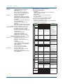
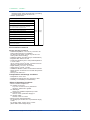
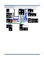
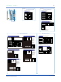
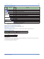
nTerminal Arrangement
Terminal Arrangement for UT75A Single Loop Control (for the terminal arrangements of other control
modes, see the user manual.)
code:
Control output OUT (Suffix
Type1=-0 or -5)
Relay contact output
NC
101
NO
102
COM
103
Factory default: PV input
type is undefined.
PV as standard)
TC input
RTD input
(Equipped
External contact output (relay)
Alarm-2 output
( PV low limit)
Common
Alarm-1 output
(PV high limit)
106
AL1
Common
- 203
101
-112
501
-512
401
-412
101
501
401
301
-312
201
-212
301
201
302
202
503
303
203
109
104
504
24 V AC/DC power supply
N
- 110
L
+ 111
112
112
CAUTION
Do not use a 100-240 V AC power
supply for the 24 V AC/DC model;
otherwise, the instrument will
malfunction.
+ 207
E1-terminal area
502
0-20 mA DC,
4-20 mA DC,
Voltage pulse (12 V)
508
COM
509
14.5-18.0 V DC
(Max. 21 mA DC)
+ 207
- 208
Can be used for retransmission output or 15 V DC loop power supply when
current/voltage pulse output is not used for control output.
Current output range can be changed.
In Position proportional type, can be used for retransmission output or 15 V
DC loop power supply.
304
204
505
305
205
506
306
206
107
507
407
307
207
108
508
408
308
208
109
509
409
309
209
Factory default: No function
210
STOP when DI2=ON
RUN when DI2=OFF
210 DI2
AUTO when DI1=ON
MAN when DI1=OFF
211 DI1
211
212 COM
212
510
110
410
310
111
511
411
311
211
112
512
412
312
212
E3-terminal area
Contact input
DI (Equipped as standard)
External contact input
No-voltage
contact
Common
E2-terminal area
UT
209 DI3
Transistor contact
209
210
UT +5V
DI3
DI2
DI1
+5V
+5V
COM
Contact rating: 12 V DC, 10 mA or more
Function can be assigned to the terminals with no function.
(Suffix code: Type 1=-5)
Cooling-side control output
Position proportional control output VALV
LOW
(reverse)
- 208
105
(Suffix code: Type1=-1)
507
+ 207
Default: 4-20 mA DC
(24 V AC/DC power supply: Optional suffix code /DC)
HIGH
(direct)
0-20 mA DC,
4-20 mA DC
- 208
106
Allowable range:
100-240 V AC (+10%/-15%)
(free voltage)
50/60 Hz shared
Relay contact output
- 206
Control output OUT (Suffix code: Type1=-0, -1 or -5)
103
111
14.5-18.0 V DC
(Max. 21 mA DC)
Current/voltage pulse output Retransmission output 15 V DC loop power supply
102
Power supply
L
+ 202
107
110
- 206
Load resistance 600 Ω or less
Default: 4-20 mA DC
108
Relay contact rating: 240 V AC, 1 A
30 V DC, 1 A (resistance load)
100-240 V AC power supply
- 203
+ 204
E4-terminal area
105
AL2
B 203
Default: Undefined
UT
104
Common
RET (Equipped as standard)
Current (mA) input Voltage (mV, V) input
Contact output ALM as standard)
AL3
4-20 mA DC or
0-20 mA DC
b 202
- 203
Alarm-3 output
(PV high limit)
Retransmission output
Retransmission output 15 V DC loop power supply Can be used for 15 V DC loop
power supply when not used for
Default: PV
retransmission output.
retransmission
+ 205
+ 205
A 201
+ 202
Contact rating: 250 V AC, 3 A
30 V DC, 3 A (resistance load)
N
(Equipped
PV input
Relay contact output
Feedback input
100%
510
511
0%
512
Contact rating: 250 V AC, 3A Resistance: 100 Ω to 2.5 kΩ
30 V DC, 3 A
(resistance load)
Feedback input
Current (mA)
input
+ 510
511
NC
507
NO
508
COM
509
OUT2
Can be used for retransmission output or 15 V
DC loop power supply when current/voltage
pulse output is not used for control output.
Current output range can be changed.
Contact rating: 250 V AC, 3 A
30 V DC, 3 A (resistance load)
OUT2
Current/voltage pulse output Retransmission output 15 V DC loop power supply
Default: Undefined
+ 511
0-20 mA DC,
4-20 mA DC,
Voltage pulse (12V)
- 512
- 512
0-20 mA DC,
4-20 mA DC
+ 511
- 512
14.5-18.0 V DC
(Max. 21 mA DC)
+ 511
- 512
Default: 4-20 mA DC
When feedback input is current
All Rights Reserved. Copyright © 2013, Yokogawa Electric Corporation
GS 05P01B41-01EN
Jun. 28, 2013-00