1
12
<<Contents>> <<Index>>
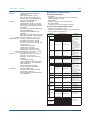
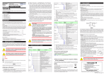
nExternal Dimensions and Panel Cutout Dimensions
65
Bracket
20
Unit: mm
Terminal cover
94.6
105.2
96
96
91.6
11
Bracket
1 to 10 mm (panel thickness)
• Side-by-side close mounting
[(N-1)×96+92] +0.8
0
• General mounting
92 +0.8
0
117 min.
145
min.
(53)
92+0.8
0
92+0.8
0
(25)
“N” stands for the number of controllers to be
installed.
However, the measured value applies if N≥5.
Normal tolerance:
±(value of JIS B 0401-1998 tolerance class IT18)/2
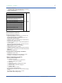
nConstruction, Mounting, and Wiring
•Dust-proof and drip-proof: IP66 (Front panel) (Except for side-by-side close mounting)/NEMA4 *
*:
Hose down test only
•Material: Polycarbonate resin (Flame retardancy: UL94 V-0)
•Case color: White (Light gray) or Black (Light Charcoal gray)
•Weight: 0.5 kg or less
•External dimensions (mm): 96 (width) x 96 (height) x 65 (depth from the panel surface)
•Mounting: Direct panel mounting; mounting bracket, one each for upper and lower mounting
•Panel cutout dimensions (mm): 92+0.8/0 (width) x 92+0.8/0 (height)
•Mounting position: Up to 30 degrees above the horizontal. No downward titling allowed.
•Wiring: M3 screw terminal with square washer (signal wiring and power)
All Rights Reserved. Copyright © 2013, Yokogawa Electric Corporation
GS 05P01B41-01EN
Jun. 28, 2013-00