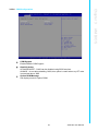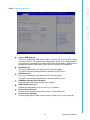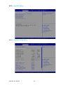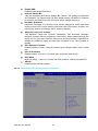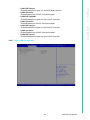
1
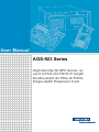
User Manual AGS-923 Series High Density 2U GPU Server, w/ up to 4 PCIe x16 FH/10.5" length Double-depth &1 PCIe x8 FH/HL Single-depth Expansion Card Copyright The documentation and the software included with this product are copyrighted 2014 by Advantech Co., Ltd. All rights are reserved. Advantech Co., Ltd. reserves the right to make improvements in the products described in this manual at any time without notice. No part of this manual may be reproduced, copied, translated or transmitted in any form or by any means without the prior written permission of Advantech Co., Ltd. Information provided in this manual is intended to be accurate and reliable. However, Advantech Co., Ltd. assumes no responsibility for its use, nor for any infringements of the rights of third parties, which may result from its use. Acknowledgements Intel and Pentium are trademarks of Intel Corporation. Microsoft Windows and MS-DOS are registered trademarks of Microsoft Corp. All other product names or trademarks are properties of their respective owners. Product Warranty (2 Years) Advantech warrants to you, the original purchaser, that each of its products will be free from defects in materials and workmanship for two years from the date of purchase. This warranty does not apply to any products which have been repaired or altered by persons other than repair personnel authorized by Advantech, or which have been subject to misuse, abuse, accident or improper installation. Advantech assumes no liability under the terms of this warranty as a consequence of such events. Because of Advantech’s high quality-control standards and rigorous testing, most of our customers never need to use our repair service. If an Advantech product is defective, it will be repaired or replaced at no charge during the warranty period. For outof-warranty repairs, you will be billed according to the cost of replacement materials, service time and freight. Please consult your dealer for more details. If you think you have a defective product, follow these steps: 1. Collect all the information about the problem encountered. (For example, CPU speed, Advantech products used, other hardware and software used, etc.) Note anything abnormal and list any onscreen messages you get when the problem occurs. 2. Call your dealer and describe the problem. Please have your manual, product, and any helpful information readily available. 3. If your product is diagnosed as defective, obtain an RMA (return merchandize authorization) number from your dealer. This allows us to process your return more quickly. 4. Carefully pack the defective product, a fully-completed Repair and Replacement Order Card and a photocopy proof of purchase date (such as your sales receipt) in a shippable container. A product returned without proof of the purchase date is not eligible for warranty service. 5. Write the RMA number visibly on the outside of the package and ship it prepaid to your dealer. AGS-923 User Manual Part No. 2001S92300 Edition 1 Printed in Taiwan July 2015 ii A Message to the Customer Advantech Customer Services Each and every Advantech product is built to the most exacting specifications to ensure reliable performance in the harsh and demanding conditions typical of industrial environments. Whether your new Advantech equipment is destined for the laboratory or the factory floor, you can be assured that your product will provide the reliability and ease of operation for which the name Advantech has come to be known. Your satisfaction is our primary concern. Here is a guide to Advantech’s customer services. To ensure you get the full benefit of our services, please follow the instructions below carefully. Technical Support We want you to get the maximum performance from your products. So if you run into technical difficulties, we are here to help. For the most frequently asked questions, you can easily find answers in your product documentation. These answers are normally a lot more detailed than the ones we can give over the phone. So please consult this manual first. If you still cannot find the answer, gather all the information or questions that apply to your problem, and with the product close at hand, call your dealer. Our dealers are well trained and ready to give you the support you need to get the most from your Advantech products. In fact, most problems reported are minor and are easily solved over the phone. In addition, free technical support is available from Advantech engineers every business day. We are always ready to give advice on application requirements or specific information on the installation and operation of any of our products. Declaration of Conformity FCC Class A Note: This equipment has been tested and found to comply with the limits for a Class A digital device, pursuant to part 15 of the FCC Rules. These limits are designed to provide reasonable protection against harmful interference when the equipment is operated in a commercial environment. This equipment generates, uses, and can radiate radio frequency energy and, if not installed and used in accordance with the instruction manual, may cause harmful interference to radio communications. Operation of this equipment in a residential area is likely to cause harmful interference in which case the user will be required to correct the interference at his own expense. iii AGS-923 User Manual Safety Information Retain and follow all product safety and operating instructions provided with your equipment. In the event of a conflict between the instructions in this guide and the instructions in equipment documentation, follow the guidelines in the equipment documentation. Observe all warnings on the product and in the operating instructions. To reduce the risk of bodily injury, electric shock, fire and damage to the equipment, observe all precautions included in this guide. You must become familiar with the safety information in this guide before you install, operate, or service Advantech products. Machine Room Environment Make sure that the area in which you install the system is properly ventilated and climate-controlled. Ensure that the voltage and frequency of your power source match the voltage and frequency inscribed on the electrical rating label of the equipment. Do not install the system in or near a plenum, air duct, radiator, or heat register. Never use the product in a wet location. Equipment Chassis Do not block or cover the openings to the system. Never push objects of any kind through openings in the equipment. Dangerous voltages might be present. Conductive foreign objects can produce a short circuit and cause fire, electric shock, or damage to your equipment. Lift equipment using both hands and with your knees bent. Rack Mount Instructions The following or similar rack-mount instructions are included with the installation instructions: Elevated Operating Ambient - If installed in a closed or multi-unit rack assembly, the operating ambient temperature of the rack environment may be greater than room ambient. Therefore, consideration should be given to installing the equipment in an environment compatible with the maximum ambient temperature (Tma) specified by the manufacturer. Reduced Air Flow - Installation of the equipment in a rack should be such that the amount of air flow required for safe operation of the equipment is not compromised. Mechanical Loading - Mounting of the equipment in the rack should be such that a hazardous condition is not achieved due to uneven mechanical loading. Circuit Overloading - Consideration should be given to the connection of the equipment to the supply circuit and the effect that overloading of the circuits might have on overcurrent protection and supply wiring. Appropriate consideration of equipment nameplate ratings should be used when addressing this concern. Reliable Earthing - Reliable earthing of rackmounted equipment should be maintained. Particular attention should be given to supply connections other than direct connections to the branch circuit (e.g. use of power strips)." AGS-923 User Manual iv Make sure only one component is extended at a time. A rack might become unstable if more than one component is extended. Equipment Batteries* The system battery contains lithium manganese dioxide. If the battery pack is not handled properly, there is risk of fire and burns. Do not disassemble, crush, puncture, short external contacts, or dispose of the battery in fire or water. Do not expose the battery to temperatures higher than 60°C (140°F). The system battery is not replaceable. If the battery is replaced by an incorrect type, there is danger of explosion. Replace the battery only with a spare designated for your product. Do not attempt to recharge the battery. Dispose of used batteries according to the instructions of the manufacturer. Do not dispose of batteries with the general household waste. To forward them to recycling or proper disposal, use the public collection system or return them to Adavantech, your authorized Advantech partner, or their agents. Equipment Modifications Do not make mechanical modifications to the system. Advantech is not responsible for the regulatory compliance of Advantech equipment that has been modified. Equipment Repairs and Servicing The installation of internal options and routine maintenance and service of this product should be performed by individuals who are knowledgeable about the procedures, precautions, and hazards associated with equipment containing hazardous energy levels. Do not exceed the level of repair specified in the procedures in the product documentation. Improper repairs can create a safety hazard. Allow the product to cool before removing covers and touching internal components. Remove all watches, rings, or loose jewelry when working before removing covers and touching internal components. Do not use conductive tools that could bridge live parts. Use gloves when you remove or replace system components; they can become hot to the touch. – If the product sustains damage requiring service, disconnect the product from the AC electrical outlet and refer servicing to an authorized service provider. Examples of damage requiring service include: – The power cord, extension cord, or plug has been damaged. – Liquid has been spilled on the product or an object has fallen into the product. – The product has been exposed to rain or water. – The product has been dropped or damaged. – The product does not operate normally when you follow the operating instructions. v AGS-923 User Manual Note! Danger of explosion if battery is incorrectly replaced. Replace only with the same or equivalent type recommended by the manufacture. Discard used batteries according to the manufacture's instructions. Danger d'explosion si la batterie est remplacée de façon incorrecte. Remplacez-la uniquement avec le même type ou équivalent recommandé par la fabrication. Jetez les piles usagées selon les instructions du fabricant. Battery Information Batteries, battery packs, and accumulators should not be disposed of as unsorted household waste. Please use the public collection system to return, recycle, or treat them in compliance with the local regulations. AGS-923 User Manual vi Peripheral Compatibility Category Advantech PN Vendor System AGS-923I-R14A1E Advantech IPMI sku(quad lan ports) 96MPXE-1.9-15M20T Intel XEON 1.9G 15M 2011P 6CORE E52609V3 96MPXE-2.2-30M20T Intel XEON 2.2G 30M 2011P 12CORE E52658V3 96MPXE-2.4-15M20T Intel XEON 2.4G 15M 2011P 6CORE E52620V3 96MPXE-2.5-30M20T Intel XEON 2.6G 20M 2011P 8CORE E52640V3 96MPXE-2.5-30M20T Intel XEON 2.5G 30M 2011P 12CORE E52680V3 TBD Intel Xeon E5-2698 v3/2.3GHz/16cores 135W TBD Intel Xeon E5-2695 v3/2.3GHz/14cores 120W TBD Intel Xeon E5-2690 v3/2.6GHz/12cores 135W TBD Intel Xeon E5-2683 v3/2.0GHz/14cores 120W TBD Intel Xeon E5-2680 v3/2.5GHz/12cores 120W TBD Intel Xeon E5-2670 v3/2.3GHz/12cores 120W TBD Intel Xeon E5-2667 v3/3.2GHz/8cores 135W TBD Intel Xeon E5-2660 v3/2.6GHz/10cores 105W TBD Intel Xeon E5-2658A v3/2.2GHz/12cores 105W TBD Intel Xeon E5-2658 v3/2.2GHz/12cores 105W TBD Intel Xeon E5-2650L v3/1.8GHz/12cores 65W CPU Memory *SATA HDD CPU heatsink Riser Card Power supply Part Description TBD Intel Xeon E5-2650 v3/2.3GHz/10cores 105W TBD Intel Xeon E5-2648L v3/1.8GHz/12cores 75W TBD Intel Xeon E5-2643 v3/3.4GHz/6cores 135W TBD Intel Xeon E5-2640 v3/2.6GHz/8cores 90W TBD Intel Xeon E5-2637 v3/3.5GHz/4cores 135W TBD Intel Xeon E5-2630L v3/1.8GHz/8cores 55W TBD Intel Xeon E5-2630 v3/2.4GHz/8cores 85W AQD-D4U4GR21-SG Advantech 4G R-DDR4-2133 1.2V 512X8 SAM AQD-D4U4GR21-HG Advantech 4G R-DDR4-2133 1.2V 512X8 HYX AQD-D4U8GR21-SG Advantech 8G R-DDR4-2133 1.2V 512X8 SAM AQD-D4U8GR21-HZ Advantech 8G R-DDR4-2133 1.2V 512X8 HYX AQD-D4U16R21-HZ Advantech 16G R-DDR4-2133 1.2V 512X8 HYX 96ND500G-ST-SG7K2 SEAGATE 500G 2.5" ST 7KRPM 64M 0.6"H(G) 96ND1T-ST-SG7KE SEAGATE 1T 2.5" SATA 7KRPM 64M 0.6"H(G) 96ND2TB-ST-SG7KE SEAGATE Ent 2.5" 2TB 7KRPM SATA 128MB 512E 1960063011N001 CoolJagLGA-2011 CPU cooler for 2U 9696910R20E Advantech AGS-920 UM x8 riser 9696920R00E Advantech AGS-920 UL x16 riser 9696920R10E Advantech AGS-920 LL x16 riser 9696920R30E Advantech AGS-920 LR x16 riser 1757004662-01 Advantech FSP1400W power module vii AGS-923 User Manual SATA DOM RAID Card RAID Card cable SAS HDD Note! SQF-SDMM2-16G-9CB Advantech 16G MLC SATA DOM SATA3 interface SQF-SDMM2-32G-9CB Advantech 32G MLC SATA DOM SATA3 interface SQF-SDMM264GS7CB 64G MLC SATA DOM SATA2 interface Advantech SQF-SDMS2-32GS7CB Advantech 32G SLC SATA DOM SATA2 interface 96RC-SAS-4P-PE-LS LSI 9240-4i SAS/SATA RAID card 96RC-SAS-4P-PE-LS2 LSI 9260-4i SAS/SATA RAID card 96CB-SAS-SATA-4P1 - CABLE MINI SAS TO 4-PORT SATA 1M Without SGPIO function 96ND300G-SSSG10KE SEAGATE SG Enterprise 2.5" 300GB 10KRPM SAS 64MB 96ND600G-SSSG10KE SEAGATE SG Enterprise 2.5" 600GB 10KRPM SAS 64MB 96ND900G-SSSG10KE SEAGATE SG Enterprise 2.5" 900GB 10KRPM SAS 64MB AGS-923 system MUST use the SSD or enterprise level SATA HDD or SAS HDD. Initial Inspection Before power up the system, please make sure that the following materials have been shipped: 1 x AGS-923 system 1 x AGS-923 Startup Manual 1 x Driver CD (User Manual is included) 2 x CPU heatsink 1 x Slide rail kit 2 x Mounting ears with handle 1 x Warranty card 8 x power cable for expansion cards (pre-assembled in the system) 1 x CPU air duct (pre-assembled in the system) If any of these items are missing or damaged, contact distributor or sales representative immediately. We have carefully inspected the AGS-923 mechanically and electrically before shipment. It should be free of marks and scratches and in perfect working order upon receipt. When unpacking the AGS-923, check it for signs of shipping damage. (For example, damaged box, scratches, dents, etc.) If it is damaged or it fails to meet the specifications, notify our service department or local sales representative immediately. Also notify the carrier. Retain the shipping carton and packing material for inspection by the carrier. After inspection, we will make arrangements to repair or replace the unit. Order Information Part number Expansion slot Lan port IPMI AGS-923I-R14A1E 4*PCIe x16 + 1*PCIe x8 4 Yes AGS-923 User Manual viii Contents Chapter Chapter 1 Overview...............................................1 1.1 1.2 1.3 1.4 1.5 1.6 1.7 Introduction ............................................................................................... 2 Features .................................................................................................... 2 System Specifications ............................................................................... 3 System Layout, LED, Jumpers and Connectors ....................................... 5 1.4.1 LED Definitions ............................................................................. 6 1.4.2 Jumpers ........................................................................................ 7 1.4.3 Connectors.................................................................................... 8 Block Diagram........................................................................................... 9 System Memory ........................................................................................ 9 Memory Installation Procedures.............................................................. 10 2 Setting up ...........................................11 2.1 Before you Begin..................................................................................... 12 2.1.1 Work Area ................................................................................... 12 2.1.2 Tools ........................................................................................... 12 2.1.3 Precautions ................................................................................. 12 Installing Motherboard Components ....................................................... 13 2.2.1 Removing the Chassis Cover ..................................................... 13 2.2.2 Installing the CPU and Heatsink ................................................. 14 2.2.3 Installing the Memory.................................................................. 18 2.2.4 Installing Hard Drives.................................................................. 19 2.2.5 Installing PCIe x16 Expansion Cards.......................................... 21 2.2.6 Installing PCIe x8 Expansion Card ............................................. 25 Rack Mounting ........................................................................................ 28 2.3.1 Installing the Server in a Rack .................................................... 28 2.2 2.3 Chapter Chapter Chapter 3 AMI BIOS ............................................33 3.1 3.2 Introduction ............................................................................................. 34 BIOS Setup ............................................................................................. 35 3.2.1 Main Menu .................................................................................. 35 3.2.2 Advanced BIOS Features Setup................................................. 36 3.2.3 Intel RC Setup............................................................................. 48 3.2.4 Server Management ................................................................... 68 3.2.5 Security ....................................................................................... 72 3.2.6 Boot............................................................................................. 73 3.2.7 Save & Exit ................................................................................. 74 4 Chipset Software Installation Utility 75 4.1 4.2 4.3 Before You Begin .................................................................................... 76 Introduction ............................................................................................. 76 4.2.1 Main Menu .................................................................................. 76 Windows OS Driver Setup ...................................................................... 77 5 VGA Setup ..........................................79 5.1 5.2 Introduction ............................................................................................. 80 Windows Series Driver Setup ................................................................. 80 ix AGS-923 User Manual Chapter 6 LAN Configuration / .......................... 81 Chapter 6 SATA RAID & AHCI / ......................... 81 Chapter 6 USB 3.0 Setup ................................... 81 6.1 6.2 6.3 LAN Configuration................................................................................... 82 6.1.1 Introduction ................................................................................. 82 6.1.2 Features...................................................................................... 82 6.1.3 Installation................................................................................... 82 6.1.4 Windows Series Driver Setup (LAN)........................................... 83 AHCI & SATA RAID ................................................................................ 84 USB3.0.................................................................................................... 85 Appendix A Programming the Watchdog Timer . 87 A.1 A.2 Watchdog Timer Overview...................................................................... 88 Programming the Watchdog Timer ......................................................... 88 AGS-923 User Manual x Chapter 1 Overview 1 1.1 Introduction The AGS-923 is a high performance Intel Xeon E5-2600 v3 series system for servergrade IPC applications that require high computing power & multi-expansion slots in 2U system. This system supports Intel Xeon E5-2600 v3 series processor and DDR4 1600/1866/2133 MHz memory up to 256 GB. AGS-923 provides 4 x PCIe x16 slot (x16 link)* + 1 x PCIe x8 slot (x8 link)*. In addition, the AGS-923 has four Gigabit Ethernet LAN ports via four dedicated PCIex1 gen2 bus, which offer bandwidth up to 500 MB/s, eliminating network bottlenecks. The fourth RJ-45 LAN connector which is also support IPMI* function, it allows remote control. High reliability and outstanding performance makes AGS-923 the ideal platform for industrial server applications. By using the Intel C612 chipset, the AGS-923 offers a variety of features such as 8 onboard SATA III interfaces(4 from SATA III and 4 from slave SATA III on-board); it supports IRST (Intel Rapid Storage Technology) and provides RAID 0, 1, 10 and 5 (Windows only*); and it has 4 USB 2.0 and 2 USB 3.0 (2 USB 2.0 in front side, 2 USB 3.0 in rear side, 2 USB 2.0 are internal Type-A connectors). These powerful I/O capabilities ensure even more reliable data storage capabilities and high-speed I/O peripheral connectivity. 1.2 Features General Intel E5-2600 v3 processor support: AGS-923 supports two Intel E5-2600 v3 series Six ~ eighteen core processors. High performance I/O capability: Four Gigabit LAN, 4* PCIe x16 slot (x16 link) + 1* PCIe x8 slot (x8 link), 8 SATA connectors and 4 USB 2.0 and 2 USB 3.0 ports. Proprietary form factor with industrial features: AGS-923 provides industrial features like long product lifecycle, reliable operation, watchdog timer, etc. IPMI 2.0 support: AGS-923 equipped with ASPEED 2400 BMC chip supports IPMI 2.0 (Intelligent Platform Management Interface 2.0) via fourth sharing LAN port. KVM over IP: AGS-923 KVM over IP function allows remote control of system through your own computer. Note! 1. 2. 3. 4. AGS-923 User Manual Each PCIe x16 slot could install a full-height / 10.5" length / doubledepth expansion card. Each PCIe x8 slot could install a full-height / half-length / single depth expansion card. IPMI module will be only included in AGS-923I sku. Please refer to the release note of each Linux OS for Intel's C612 chipset SATA RAID function support. 2 Processor Dual Intel LGA2011 Xeon processor sockets Supports Intel Xeon E5-2600 v3 series processor Supports the processor TDP up to 145 W. Memory Capacity Intel Xeon processor supports DDR4 memory bus Total 8 288-pin memory slots provided Supports total capacity up to 256 GB 4 channels per processor, 1 memory slot per channel Memory Type Supports DDR4 1600/1866/2133 MHz ECC Registered / ECC Unbuffered / Non-ECC Unbuffered Modules. Memory Sizes Each memory slot supports 4 GB, 8 GB, 16 GB and 32 GB memory modules Memory Voltage 1.2 V Error Detection Corrects single-bit errors Detects double-bit errors (using ECC memory) CPU Chapter 1 1.3 System Specifications System Memory Chipsets Intel C612 PCH provide 8xPCIe x1 Gen2 lanes Network Controllers 4 x Intel I210 Gigabit Ethernet Controller connected to C612 through PCIe Gen2 Lane. Above network Supports 10BASE-T, 100BASE-TX, and 1000BASE-T, with RJ-45 output VGA ASPEED AST 2400 controller with 64 MB VGA memory provides basic 2D VGA function. Super I/O Nuvoton NCT6776F chip provides motherboard, RS-232, parallel port and hardware monitor functions. BMC Sharing with the fourth RJ45 port. Input / Output Storage LAN 4 x RJ-45 LAN ports (10/100/1000 Base-T LAN). USB VGA 1 x D-Sub port Serial Port / Header 2 x internal header (2 x 5 pin, 2.5 mm pitch) for UART port. Total 8 x 2.5" HDD bays, 8 ports provide 6 Gb/s bandwidth. RAID 0, 1, 5, 10 support (Windows only). 2 x USB 3.0 ports at rear window. 2 x USB 2.0 ports at front window. 2 x internal Type-A USB 2.0 port. Power Supply Power 80 PLUS Platinum 1+1 redundant power supply 900 W @ 100 ~ 120 V 1400 W @ 200 ~ 240 V Power Connector Expansion Card power 8 x 6 pin 12V power connector for 6 pin / 8 pin expansion card. Expansion Slots 3 AGS-923 User Manual Overview On-board Devices PCI-express 4 x PCI-E x16 slot (Gen3 x16 link) – PCIEX16_SLOT2 (from CPU 0) – PCIEX16_SLOT3 (from CPU 0) – PCIEX16_SLOT6 (from CPU 1) – PCIEX16_SLOT5 (from CPU 1) 1 x PCI-E x8 slot (Gen3 x8 link) – PCIEX8_SLOT1 (from CPU0) System BIOS BIOS type 64 Mb SPI Flash EEPROM with AMI BIOS PC Health Monitoring Voltage Monitors for CPU Cores, +3.3 V, +5 V, +12 V, +5 V Standby, VBAT Fan Temperature Monitoring for CPU0 & CPU1 (PECI) Monitoring for System (HWM) Other Features (Case Open) 4 * 80 x 38 + 1 * 80x20 + 1 * 80 x 38 (optional) high speed fan All fans with tachometer status monitoring Fan speed control for all fan connectors Chassis intrusion detection Chassis Intrusion header Operating Environment / Compliance RoHS RoHS Compliant 6/6 Pb Free Environmental Spec. AGS-923 User Manual Operating Temperature: 0 to 40° C Non-operating Temperature: -20 to 60° C Operating Relative Humidity: 10% to 85% (non-condensing) Non-operating Relative Humidity: 10% to 95% (non-condensing) 4 Connectors on the AGS-923 are linked to external devices such as hard disk drives. In addition, AGS-923 has a jumper that are used to clean CMOS for BIOS. The tables below list the functions of each jumper and connector. Later sections in this chapter give instructions for setting jumpers. Chapter 2 gives instructions for connecting external devices to AGS-923. JME1 SATA1 ~ SATA8 E5-2600 v3 CPU socket 2*12V output power connector f or expansion card 8038 System f an PCIEX16_SLOT2 1+1 1400W Redundant power module PCIEX8_SLOT1 VGA1 LAN1 ~ LAN4 8*2.5” HDD Bay USB0_1 COM1 & COM2 PCIEX16_SLOT3 PCIEX16_SLOT5 LPC connector BMC Module (AGS-923I only) 8020 3*8038 6*12V output PCIEX16_SLOT6 System intrusion 4*USB2.0 port System f an power connector System f an switch JCMOS1 f or expansion card LAN1~4 LED FP USB1_2 8*2.5” SATA HDD bay Power LED HDD status LED Power button Location switch & LED Error LED Reset button Power module LED 1+1 1400W Redundant power module HDD activity LED Location button & LED Error LED LAN1 LAN2 LAN3 VGA1 5 LAN4 USB0_1 AGS-923 User Manual Overview DDR4 DIMM slot Chapter 1 1.4 System Layout, LED, Jumpers and Connectors BP_P1 BP_P2 SMBUS1 SATA SGPIO1 & 2 TCN1 5V LED1 & 5VSB LED1 & BMC LED1 TCN2 CPU1 CPU0 FP USB3 USB4 SGPIO1 CN1 SATA3 SMBUS1 SATA2 SATA1 SATA4 FP USB1_2 1.4.1 LED Definitions Front l/O LED LED Power LED LAN1 ~ LAN4 LED Error LED Location LED State Color Description On Green System is turned on Blinking Green System is under S1 or S4 state Off Off Power off Blinking Green LAN active On Green LAN linked Off Off LAN unlinked On Red Fan fail; Over-voltage Off Off No failure On Blue System identified Off Off System unidentified HDD LED HDD status Status LED Color: Amber Activity LED Color: Green No driver present or power disconnected Off - No activity - On Access activity - Blinking Driver present HDD fail On (only work under the RAID mode) Identify (locate the HDD) 4 Hz Blinking (only work under the RAID mode) SATA/SAS RAID building 1 Hz Blinking (only work under the RAID mode) AGS-923 User Manual 6 LED State 5V LED1 5VSB LED1 Color Description On Green System power on Off Off On Green System power on, in sleep mode or in soft-off mode Off Off Power off No AC power input Chapter 1 On-Board LED BMC LED1 Blinking Green BMC Controller is working normally (AGS-923I sku only) LED Left LED LAN1 ~ LAN4 LED Right LED Description Off Green 10 Mbps linked Off Blinking Green 10 Mbps Active Amber Green 100 Mbps linked Amber Blinking Green 100 Mbps Active Green Green 1000 Mbps linked Green Blinking Green 1000 Mbps Active Off Off No Link Rear I/O LED(2) Error LED Location LED On Red Off Off No failure On Blue System identified Off Off System unidentified Blinking Red Power module LED Fan fail; Over voltage No AC power to this module Blinking Blue AC present standby output on On Red Power supply failure On Blue Power supply DC output ON and OK Off Off No AC power to power module 1.4.2 Jumpers Label Function Default JCMOS1 CMOS clear 1-2 JME1 ME update 1-2 1 1 Keep CMOS data / Disable ME update 7 Clear CMOS data / Enable ME update AGS-923 User Manual Overview Rear I/O LED (1) 1.4.3 Connectors CPU0 Intel LGA2011 CPU0 socket CPU1 Intel LGA2011 CPU1 socket SYS FAN1 ~ SYS FAN9 System fan connector (4-pin) DIMMA0 Channel A DIMM0 of CPU0 DIMMB0 Channel B DIMM0 of CPU0 DIMMC0 Channel C DIMM0 of CPU0 DIMMD0 Channel D DIMM0 of CPU0 DIMME0 Channel E DIMM0 of CPU1 DIMMF0 Channel F DIMM0 of CPU1 DIMMG0 Channel G DIMM0 of CPU1 DIMMH0 Channel H DIMM0 of CPU1 TCN1 ~ TCN2 Expansion card thermal sensor cable connector (2-pin) GPU 6P P1 ~ GPU 6P P8 12V power output connector for expansion card (6-pin) BMC1 ~ BMC2 IPMI module connector SATA1 Serial ATA1 hard drive connector (SATAIII) SATA2 Serial ATA2 hard drive connector (SATAIII) SATA3 Serial ATA3 hard drive connector (SATAIII) SATA4 Serial ATA4 hard drive connector (SATAIII) sSATA1 Serial ATA5 hard drive connector (SATAIII) sSATA2 Serial ATA6 hard drive connector (SATAIII) sSATA3 Serial ATA1 hard drive connector (SATAIII) sSATA4 Serial ATA2 hard drive connector (SATAIII) FP SLOT1 The slot for front panel board. PCIEX8 SLOT1 PCIe x8 slot (gen3 x8 link) from CPU0 PCIEX16 SLOT2 PCIe x16 slot (gen3 x16 link) from CPU0 PCIEX16 SLOT3 PCIe x16 slot (gen3 x16 link) from CPU0 PCIEX16 SLOT5 PCIe x16 slot (gen3 x16 link) from CPU1 PCIEX16 SLOT6 PCIe x16 slot (gen3 x16 link) from CPU1 LPC1 LPC port for debug & TPM module COM1 ~ COM2 Serial port : RS-232 SATA SGPIO 1/2 Supports Serial_Link interface for onboard SATA connections SMBUS1 For HDD status monitoring BP P1 ~ P2 5V power output connector for HDD back plane FP USB 1_2 USB port 3, 4 FP USB 3 USB port 5 (internal type-A, horizontal) FP USB 4 USB port 6 (internal type-A, vertical) AGS-923 User Manual 8 Chapter 1 1.5 Block Diagram Overview 1.6 System Memory AGS-923 has eight 288-pin memory slots for DDR4 1600/1866/2133 MHz memory modules with maximum capacity of 256 GB (Maximum 32 GB for each DIMM). AGS-923 supports registered DIMMs ONLY. 9 AGS-923 User Manual 1.7 Memory Installation Procedures Single processor installed (CPU0) DIMM A0 DIMM B0 DIMM C0 DIMM D0 Dual processor installed (CPU0 & CPU1) 1 2 3 4 2 3 4 5 6 7 Quantity of 8 memory module installed V V V V V V V V V V V V V V V V V V V V V V V V V V V V V DIMM E0 V DIMM F0 DIMM G0 DIMM H0 AGS-923 User Manual V V V V V V V V V V V V V V V 10 Chapter 2 Setting up 2 2.1 Before you Begin This chapter explains how to install the CPUs, CPU heatsinks, memory modules, and hard drives. Instructions on inserting add on cards are also given. 2.1.1 Work Area Make sure you have a stable, clean working environment. Dust and dirt can get into components and cause malfunctions. Use containers to keep small components separated. Putting all small components in separate containers prevents them from becoming lost. Adequate lighting and proper tools can prevent you from accidentally damaging the internal components. 2.1.2 Tools The following procedures require only a few tools, including the following: A cross head (Phillips) screwdriver A grounding strap or an anti-static pad Most of the electrical and mechanical connections can be disconnected with your hands. It is recommended that you do not use pliers to remove connectors as it may damage the soft metal or plastic parts of the connectors. 2.1.3 Precautions Components and electronic circuit boards can be damaged by discharges of static electricity. Working on a system that is connected to a power supply can be extremely dangerous. Follow the guidelines below to avoid damage to AGS-923 or injury to yourself. Ground yourself properly before removing the top cover of the system. Unplug the power from the power supply and then touch a safely grounded object to release static charge (i.e. power supply case). If available, wear a grounded wrist strap. Alternatively, discharge any static electricity by touching the bare metal chassis of the unit case, or the bare metal body of any other grounded appliance. Avoid touching motherboard components, IC chips, connectors, memory modules, and leads. The motherboard is pre-installed in the system. When removing the motherboard, always place it on a grounded anti-static surface until you are ready to reinstall it. Hold electronic circuit boards by the edges only. Do not touch the components on the board unless it is necessary to do so. Do not flex or stress circuit boards. Leave all components inside the static-proof packaging that they ship with until they are ready for installation. After replacing optional devices, make sure all screws, springs, or other small parts are in place and are not left loose inside the case. Metallic parts or metal flakes can cause electrical shorts. AGS-923 User Manual 12 This section describes how to install components on to the mainboard, including CPU memory modules and add on cards. 2.2.1 Removing the Chassis Cover Follow these instructions to remove AGS-923 chassis cover. 1. Unscrew the top cover as follows. Chapter 2 2.2 Installing Motherboard Components Setting up 2. Slide the rear top cover out. 13 AGS-923 User Manual 2.2.2 Installing the CPU and Heatsink Follow the steps below to install CPUs and CPU heatsinks. 1. Locate the CPU sockets - you must install into the CPU0 socket first. 2. Pull the lever slightly away from the socket and then push it to a fully open position. AGS-923 User Manual 14 Push the CPU socket cover to a fully open position. 4. Place the CPU into the socket and make sure that the gold arrow is located in the right direction. Chapter 2 3. Setting up 15 AGS-923 User Manual 5. Take off the protection cap. 6. Close the CPU socket cover and press the lever down to secure the CPU. AGS-923 User Manual 16 8. Repeat the procedures earlier to install the second processor and heatsink. Setting up Position the heatsink on top of the CPU and secure it with 4 screws. Chapter 2 7. 17 AGS-923 User Manual 2.2.3 Installing the Memory Follow these instructions to install the memory modules onto the motherboard. 1. Locate the memory slots on the motherboard. 2. Press the memory slot locking levers in the direction of the arrows as shown in the following illustration. 3. Align the memory module with the slot. When inserted properly, the memory slot locking levers lock automatically onto the indentations at the ends of the module. Follow the recommended memory population table to install the other memory modules. AGS-923 User Manual 18 Chapter 2 Setting up 2.2.4 Installing Hard Drives The AGS-923 supports eight 2.5” hard drives. Follow these instructions to install a hard drive. 1. Press the locking lever latch and pull the locking lever open. 2. Slide the HDD tray out. 19 AGS-923 User Manual 3. Place a hard drive into the drive tray, then use the screws to secure the HDD. 4. Re-insert the HDD tray into the chassis and press the locking lever to secure the tray. AGS-923 User Manual 20 (We use PCIe x16 double-depth GPU card as sample) The AGS-923 supports four PCIe x16 expansion slots. Please follow these instructions to install the expansion cards. 1. Unscrew the riser card cage and carefully place your fingers on the card cage holding positions. Chapter 2 2.2.5 Installing PCIe x16 Expansion Cards Setting up 2. Take the card cage out from the chassis. 21 AGS-923 User Manual 3. Release the expansion card holder. 4. Unscrew the IO bracket from the card cage. 5. Install the expansion card into the card cage. AGS-923 User Manual 22 7. Move the card holder toward to the expansion card. Setting up Screw the expansion card IO bracket onto the card cage. Chapter 2 6. 23 AGS-923 User Manual 8. Screw the card holder onto the expansion card. 9. Connect the expansion card power cable to the expansion card power connector. 10. Put the card cage back into the chassis, and make sure the cage has no mechanical conflict with the chassis. AGS-923 User Manual 24 (We use PCIe x8 mini SAS to SATA RAID card as sample) The AGS-923 supports one PCIe x8 expansion slot. Please follow these instructions to install the expansion cards. 1. Unscrew the riser card bracket and release the PCIe x8 riser card. Chapter 2 2.2.6 Installing PCIe x8 Expansion Card Setting up 2. Screw the expansion card onto the riser card bracket. 25 AGS-923 User Manual 3. Install the expansion card onto the riser card. 4. Install the mini SAS to SATA cable into the expansion card, then make the cable pass through the plastic clip. 5. Install the expansion card into the chassis and secure it. AGS-923 User Manual 26 7. Install the SATA & SGPIO connector* into HDD back plane. Setting up Remove the SATA / SATA SGPIO cable from the motherboard and HDD back plane. Chapter 2 6. 27 AGS-923 User Manual Please see SATA / SAS SGPIO pin header definition as below picture. 2.3 Rack Mounting After installing the necessary components, the AGS-923 can be mounted in a rack using the supplied rack mounting kit. We strongly recommend that the minimum depth of cabinets is 1000mm. Rack mounting kit Sliding Rails x 2 Convert bracket x 4 Screws Kit x 3 2.3.1 Installing the Server in a Rack Before mounting the AGS-923 in a rack, ensure that all internal components have been installed and that the unit has been fully tested. Both side of chassis ear must be assembled before you assemble the slide rail kit. AGS-923 User Manual 28 Screws list M5 x16 M4 x9 Remove the chassis (inner) member. Pull the slide open. Then press the trigger down as shown on the drawing, and pull the chassis (inner) member out. 2. Mount the chassis (inner) member to the chassis. Each side of chassis uses 4 of screws or standoffs for slide attachment. 29 AGS-923 User Manual Setting up 1. Chapter 2 Follow these instructions to mount the AGS-923 into an industry standard 32” rack. 3. Attach the cabinet (outer) member to the rail. Insert the stag into the upper and lower square holes on EIA rail from the back of rail. Push the safety lock forward to secure the bracket. It is important to check if the safety lock is in unlocked position before mounting the brackets. 4. Mount the chassis into the cabinet. Insert the chassis (inner) member into the cabinet member as shown on the drawing. It is important to check if the ball retainer is in fully open position before install the chassis. It might cause catastrophic damage to the chassis if ball retainer is not in fully open position while mounting the chassis. While you are pushing chassis back to the cabinet, you need to release the slide from locking position by pressing the trigger down. AGS-923 User Manual 30 Instructions de montage en rack - Le rack en suivant ou similaire monter instructions sont incluses avec les instructions d'installation: Température de fonctionnement élevée - il est installé dans une unité fermée ou plusieurs Ensemble formant bâti, la température ambiante de fonctionnement de l'environnement de l'armoire peut être supérieure à la chambre ambiante. Par conséquent, il devrait être donnée à l'installation de l'équipement dans un environnement compatible avec la température ambiante maximale (Tma) spécifiée par le fabricant. Débit d'air réduit - Installation de l'équipement dans un rack doit être tel que la quantité de flux d'air nécessaire au bon fonctionnement de l'appareil ne soit pas compromise. Chargement mécanique - Le montage de l'équipement dans le rack doit être telle qu'une situation dangereuse ne soit générée à inégale chargement mécanique. Surcharge du circuit - Il faut tenir compte à la connexion de l'équipement au circuit d'alimentation et l'effet que la surcharge des circuits pourrait avoir sur la protection contre les surintensités et le câblage d'alimentation. Considération appropriée de l'équipement plaque signalétique évaluations doivent être utilisés pour répondre à cette préoccupation. Fiabilité de la mise - Fiable mise à la terre de l'équipement monté en rack doit être maintenue. Une attention particulière devrait être accordée à fournir connexions autres que les connexions directes sur le circuit de branche (par exemple l'utilisation de multiprises). 31 AGS-923 User Manual Setting up Rack Mount Instructions - The following or similar rack-mount instructions are included with the installation instructions: Elevated Operating Ambient - If installed in a closed or multi-unit rack assembly, the operating ambient temperature of the rack environment may be greater than room ambient. Therefore, consideration should be given to installing the equipment in an environment compatible with the maximum ambient temperature (Tma) specified by the manufacturer. Reduced Air Flow - Installation of the equipment in a rack should be such that the amount of air flow required for safe operation of the equipment is not compromised. Mechanical Loading - Mounting of the equipment in the rack should be such that a hazardous condition is not achieved due to uneven mechanical loading. Circuit Overloading - Consideration should be given to the connection of the equipment to the supply circuit and the effect that overloading of the circuits might have on overcurrent protection and supply wiring. Appropriate consideration of equipment nameplate ratings should be used when addressing this concern. Reliable Earthing - Reliable earthing of rackmounted equipment should be maintained. Particular attention should be given to supply connections other than direct connections to the branch circuit (e.g. use of power strips). Chapter 2 Note! AGS-923 User Manual 32 Chapter 3 AMI BIOS 3 3.1 Introduction With the AMI BIOS Setup program, you can modify BIOS settings and control the special features of your system. The Setup program uses a number of menus for making changes and turning the special features on or off. This chapter describes the basic navigation of the AGS-923 setup screens. AMI's BIOS ROM has a built-in Setup program that allows users to modify the basic system configuration. This type of information is stored in battery-backed up CMOS so it retains the Setup information when the power is turned off. Note! The BIOS setup screens shown in this chapter are for reference only, they may not exactly match what you see on your display devices. AGS-923 User Manual 34 3.2.1 Main Menu Press <Del> during bootup to enter AMI BIOS CMOS Setup Utility; the Main Menu will appear on the screen. Use arrow keys to select among the items and press <Enter> to accept or enter the sub-menu. Chapter 3 3.2 BIOS Setup AMI BIOS The Main BIOS setup screen has two main frames. The left frame displays all the options that can be configured. Grayed-out options cannot be configured; options in blue can be. The right frame displays the key legend. Above the key legend is an area reserved for a text message. When an option is selected in the left frame, it is highlighted in white. Often a text message will accompany it. System Time / System Date Use this option to change the system time and date. Highlight System Time or System Date using the <Arrow> keys. Enter new values through the keyboard. Press the <Tab> key or the <Arrow> keys to move between fields. The date must be entered in MM/DD/YY format. The time must be entered in HH:MM:SS format. 35 AGS-923 User Manual 3.2.2 Advanced BIOS Features Setup Select the Advanced tab from the AGS-923 setup screen to enter the Advanced BIOS setup screen. You can select any of the items in the left frame of the screen, such as CPU configuration, to go to the sub menu for that item. You can display an Advanced BIOS Setup option by highlighting it using the <Arrow> keys. All Advanced BIOS Setup options are described in this section. The Advanced BIOS Setup screens are shown below. The sub menus are described on the following pages. AGS-923 User Manual 36 Chapter 3 3.2.2.1 ACPI Settings AMI BIOS Enable Hibernation "Enable or disable" Hibernation. Lock Legacy Resources "Enable" or "Disable" Lock Legacy Resources. 37 AGS-923 User Manual 3.2.2.2 NCT6776 Super IO Configuration Serial Port 1 Configuration AGS-923 User Manual 38 Chapter 3 – Serial Port “Enable” or “Disable” Serial Port 1. – Change Settings To select an optimal setting for serial port 1. Serial Port 2 Configuration AMI BIOS – Serial Port “Enable” or “Disable” Serial Port 2. – Change Settings To select an optimal setting for serial port 2. 39 AGS-923 User Manual 3.2.2.3 H/W Monitor AGS-923 User Manual 40 Chapter 3 AMI BIOS Case Open Warning Enable/Disable the Chassis Intrusion monitoring function. When enabled and the case is opened, the warning message will show in POST screen. Watchdog Timer Enable and Disable the watchdog timer function. CPU Warning Temperature Set the CPU warning temperature threshold. When the system reaches the warning temperature, the speaker will beep. ACPI Shutdown Temperature Set the ACPI shutdown temperature threshold. When the system reaches the shutdown temperature, it will be automatically shut down by ACPI OS to protect the system from overheat damage. Fan Configuration When set to manual mode, fan duty setting can be changed; the range is from 10%~100%, default setting is 100%. 41 AGS-923 User Manual 3.2.2.4 Serial Port Console Redirection Console Redirection To “Enable or disable” console redirection feature. Console Redirection Settings AGS-923 User Manual 42 Chapter 3 AMI BIOS Terminal Type Select a terminal type to be used for console redirection. Options available: VT100/VT100+/ANSI /VT-UTF8. Bits Per Second Select the baud rate for console redirection. Options available: 9600/19200/57600/115200. Parity A parity bit can be sent with the data bits to detect some transmission errors. Even: parity bit is 0 if the number of 1's in the data bits is even. Odd: parity bit is 0 if number of 1's the data bits is odd. Mark: parity bit is always 1. Space: Parity bit is always 0. Mark and Space Parity do not allow for error detection. Options available: None/Even/Odd/Mark/Space. Stop Bits Stop bits indicate the end of a serial data packet. (A start bit indicates the beginning). The standard setting is 1 stop bit. Communication with slow devices may require more than 1 stop bit. Options available: 1/2. Flow Control Flow control can prevent data loss from buffer overflow. When sending data, if the receiving buffers are full, a 'stop' signal can be sent to stop the data flow. Once the buffers are empty, a 'start' signal can be sent to re-start the flow. Hardware flow control uses two wires to send start/stop signals. Options available: None/Hardware RTS/CTS. 43 AGS-923 User Manual Recorder Mode When this mode enabled, only text will be send. This is to capture Terminal data. Options available: Enabled/Disabled. Legacy OS Redirection Resolution On Legacy OS, the number of Rows and Columns supported redirection. Options available: 80x24/80X25. Putty Keypad Select function key and keypad on putty. Redirection After BIOS Post 3.2.2.5 PCI Subsystem Settings Above 4G Decoding Enables or disables 64-bit capability. Devices to be decoded in above 4G address space (Only if system supports 64-bit PCI decoding). AGS-923 User Manual 44 Chapter 3 3.2.2.6 CSM Configuration AMI BIOS CSM Support Enable/Disable CSM Support GateA20 Active UPON REQUEST - GA20 can be disabled using BIOS services. ALWAYS - do not allow disabling GA20; this option is useful when any RT code is executed above 1MB. Option ROM Message Set display mode for Option ROM. 45 AGS-923 User Manual 3.2.2.7 Trusted Computing Security Device Support Enables or disables BIOS support for security device. Purchase Advantech LPC TPM module to enable TPM function. P/N: PCATPM00A1E. AGS-923 User Manual 46 Chapter 3 3.2.2.8 USB Configuration AMI BIOS Legacy USB Support This is for supporting USB device under a legacy OS such as DOS. When choosing "AUTO", the system will automatically detect if any USB device is plugged into the computer and enable USB legacy mode when a USB device is plugged and disable USB legacy mode when no USB device is attached. XHCI Hand-off This is a workaround for OS without XHCI hand-off support. The XHCI ownership change should be claimed by XHCI driver. EHCI Hand-off This is a workaround for OS without EHCI hand-off support. The EHCI ownership change should be claimed by EHCI driver. USB Mass Storage Driver Support Enable/Disable USB mass storage driver support. USB Transfer Time-out Selects the USB transfer time-out value. [1,5,10,20sec] Device Reset Time-out Selects the USB device reset time-out value. [10,20,30,40 sec] Device Power-up Delay This item appears only when Device power-up delay item is set to [manual]. 47 AGS-923 User Manual 3.2.3 Intel RC Setup 3.2.3.1 Processor Configuration AGS-923 User Manual 48 Chapter 3 AMI BIOS Hyper-threading Enables Hyper Threading (Software Method to Enable/Disable Logical Processor threads). VMX Enables the Vanderpool Technology, takes effect after reboot. 49 AGS-923 User Manual Enable SMX Enables Safer Mode Extensions. Execute Disable Bit This item specifies the Execute Disable Bit Feature. The settings are Enabled and Disabled. The Optimal and Fail-Safe default setting is Enabled. If Disabled is selected, the BIOS forces the XD feature flag to always return to 0. Hardware Prefetcher Hardware Prefetcher is a technique that fetches instructions and/or data from memory into the CPU cache memory well before the CPU needs it, so that it can improve the load-to-use latency. Set to enable or disable. Adjacent Cache Line Prefetch The Adjacent Cache-Line Prefetch mechanism, like automatic hardware prefetch, operates without programmer intervention. When enabled through the BIOS, two 64- byte cache lines are fetched into a 128-byte sector, regardless of whether the additional cache line has been requested or not. Set to enable or disable. DCU Streamer Prefetch Enable prefetch of next L1 data line based upon multiple loads in same cache line. DCU IP Prefetcher Enable prefetch of next L1 line based upon sequential load history. DCU Mode MSR 31h Bit[0] - A write of 1 selects the DCU mode as 16KB 4-way with ECC. AES-NI Enable/disable AES-NI support. 3.2.3.2 Advanced Power Management Configuration AGS-923 User Manual 50 Chapter 3 Power technology default is “Energy Efficient”. Config TDP Option to disable/enable config TDP. AMI BIOS EIST (P-states) When enabled, OS sets CPU frequency according load. When disabled, CPU frequency is set at max non-turbo. Turbo Mode Turbo mode allows a CPU logical processor to execute a higher frequency when enough power is available not exceed CPU defined limits. P-state Coordination HW_ALL (hardware) coordination is recommended over SW_ALL and SW_ANY (software coordination). 51 AGS-923 User Manual Package C State limit There are four items for option, "C0/C1 state", "C2 state", "C6 (non Retention) state", "C6(Retention) state”. CPU C3 report Enable/Disable CPU C3(ACPI C2) report to OS. Recommended to be disabled. CPU C6 report Enable/Disable CPU C6(ACPI C2) report to OS. Recommended to be enabled. AGS-923 User Manual 52 Chapter 3 AMI BIOS ACPIT-States Enable/Disable CPU throttling by OS. Throttling reduces power consumption. 3.2.3.3 QPI Configuration 53 AGS-923 User Manual – QPI status – Link Speed Mode Select the QPI link speed as either the POR speed (Fast) or default speed (Slow). – Link Frequency Select Allows for selecting the QPI Link frequency. – Link L0p Enable Enable/Disable QPI Link0p. – Link L1 Enable Enable/Disable QPI L1. – COD Enable Enable/Disable Cluster on Die. – Early snoop Enable/Disable/Auto the early snoop item. AGS-923 User Manual 54 Chapter 3 3.2.3.4 Memory Configuration AMI BIOS Data Scrambling Enable/Disable data scrambling. Numa Enable/Disable Non-uniform Memory Access (NUMA). Memory Topology 55 AGS-923 User Manual 3.2.3.5 IIO Configuration AGS-923 User Manual 56 CPU0 PCIe configuration – IOU2 (PCIe Slot1_UM) Functions visible based on this setting: x4x4 x8 Chapter 3 AMI BIOS – IOU0 (PCIe slot2_LR) Functions visible based on this setting: x4x4x4x4 x4x4x8 x8x4x4 x8x8 x16 Auto – IOU1 (PCIe slot3_UL) Functions visible based on this setting: x4x4x4x4 x4x4x8 x8x4x4 x8x8 x16 Auto 57 AGS-923 User Manual – Link Speed Select target link speed as Gen1, Gen2, Gen3. – Link Speed Select target link speed as Gen1, Gen2, Gen3. AGS-923 User Manual 58 Chapter 3 – Link Speed Select target link speed as Gen1, Gen2, Gen3. – Non-transparent Bridge PCIe Port D Configures port as TB/NTB-NTB/NTB-RP (DON'T SELECT NTB-RP for legacy IIO on A0 Si!). AMI BIOS CPU1 PCIe configuration – IOU1 (PCIe Slot6_LL) Functions visible based on this setting: x4x4x4x4 x4x4x8 x8x4x4 x8x8 x16 Auto 59 AGS-923 User Manual – Link Speed Select target link speed as Gen1, Gen2, Gen3. – Non-transparent Bridge PCIe Port D Configures port as TB/NTB-NTB/NTB-RP (DON'T SELECT NTB-RP for legacy IIO on A0 Si!). PCI-E ASPM support (Global) This option enables/disables the ASPM support for all downstream devices. VGA priority Decides priority between onboard and 1st offboard video device found. AGS-923 User Manual 60 Chapter 3 3.2.3.6 PCH Configuration AMI BIOS SMBus Device Enable/Disable SMBus Device. Restore AC Power Loss Specify what state to go to when power is re-applied after a power failure (G3 state). PCH Compatibility RID Enable/Disable PCH Compatibility Revision ID (CRID) Functionality. PCI-E ASPM Support (Global) This option enables/disables the ASPM support for all downstream devices. xHCI Mode Mode of operation of xHCI controller. 61 AGS-923 User Manual – sSATA Controller Enables/Disables sSATA controller. – Configure sSATA as Configured as IDE/RAID/AHCI mode. – Support Aggressive Link Power Mana Enables/Disables SALP, and this item will appear when "AHCI" or "RAID" is selected. AGS-923 User Manual 62 Chapter 3 AMI BIOS – sSATA Device Type Identify the SATA port is connected to Solid State Drive or Hard Disk Drive. – Set to "AHCI Mode" to have the SATA hard disk drives use the AHCI (Advanced Host Controller Interface). The AHCI allows the onboard storage driver to enable advanced Serial ATA features that increase storage performance on random workloads by allowing the drive to internally optimize the order of commands. 63 AGS-923 User Manual – Set to "RAID Mode" to create a RAID configuration from the SATA hard disk drives. – SATA Controller Enables/Disables sSATA controller. – Configure SATA as Configured as IDE/RAID/AHCI mode. AGS-923 User Manual 64 Chapter 3 – Support Aggressive Link Power Mana Enables/Disables SALP, and this item will appear when "AHCI" or "RAID" is selected. AMI BIOS – SATA Device Type Identify the SATA port is connected to Solid State Drive or Hard Disk Drive. 65 AGS-923 User Manual – Set to "AHCI Mode" to have the SATA hard disk drives use the AHCI (Advanced Host Controller Interface). The AHCI allows the onboard storage driver to enable advanced Serial ATA features that increase storage performance on random workloads by allowing the drive to internally optimize the order of commands. – Set to "RAID Mode" to create a RAID configuration from the SATA hard disk drives. AGS-923 User Manual 66 67 AGS-923 User Manual AMI BIOS 3.2.3.7 Server ME Configuration Chapter 3 – LAN1 PXE Oprom Enable/Disable Boot option for Intel 82579LM controller. – LAN2 Controller Enable/Disable Intel I210AT Controller support. – LAN2 PXE OpROM Enable/Disable Boot option for Intel I210AT controller. – LAN3 Controller Enable/Disable Intel I210AT Controller support. – LAN3 PXE Oprom Enable/Disable Boot option for Intel I210AT controller. – LAN4 Controller Enable/Disable Intel I210AT Controller support. – LAN4 PXE Oprom Enable/Disable Boot option for Intel I210AT controller. 3.2.4 Server Management BMC Support Enable/Disable interfaces to communicate with BMC Wait for BMC If enabled, motherboard will wait 30 ~ 60 seconds until BMC module boots up completely. After that, the normal BIOS post screen will be displayed. If disabled, motherboard will not wait for BMC module's response. Wait for BMC counter Wait for BMC counter for initialize host to BMC interfaces. The MB beeps every 5 seconds to check it. System Event Log AGS-923 User Manual 68 Chapter 3 AMI BIOS – SEL Components Enable/Disable all features of system event logging during boot. – Erase SEL Choose options for erasing SEL. – When SEL is Full Choose options for reactions to a full SEL. – Log EFI Status Codes Disable the logging of EFI status codes or log only error code or only progress code or both. 69 AGS-923 User Manual BMC Self Test Log – Erase Log Erase log options. – When Log is Full Select the action to be taken when log is full. AGS-923 User Manual 70 BMC Network Configuration Chapter 3 AMI BIOS – Configuration Address Source Select to configure LAN channel parameters statically or dynamically (by BMC). Unspecified option will not modify any BMC network parameters during BIOS phase. 71 AGS-923 User Manual 3.2.5 Security AGS-923 User Manual 72 Chapter 3 3.2.6 Boot AMI BIOS Setup Prompt Timeout Number of seconds to wait for setup activation key. 16 (0x10) means indefinite waiting. Bootup NumLock State Select the keyboard NumLock state. Quiet Boot Enable/Disable quiet boot option. Boot Option Sets the system boot priorities. 73 AGS-923 User Manual 3.2.7 Save & Exit Save Changes and Exit Exit system setup after saving the changes. Discard Changes and Exit Exit system setup without saving any changes. Save Changes and Reset Reset the system after saving changes. Discard Changes and Reset Reset system setup without saving any changes. Save Changes Save changes done so far to any of the setup options. Discard Changes Discard changes done so far to any of the setup options. Restore Defaults Restore/Load default values for all the setup options. Save as User Defaults Save the changes done so far as user defaults. Restore User Defaults Restore the user defaults to all the setup options. AGS-923 User Manual 74 Chapter 4 Chipset Software Installation Utility 4 4.1 Before You Begin To facilitate the installation of the enhanced display drivers and utility software, read the instructions in this chapter carefully. The drivers for the AGS-923 are located on the software installation CD. Before beginning, it is important to note that most display drivers need to have the relevant software application already installed on the system prior to installing the enhanced display drivers. In addition, many of the installation procedures assume that you are familiar with both the relevant software applications and operating system commands. Review the relevant operating system commands and the pertinent sections of your application software’s user manual before performing the installation. 4.2 Introduction 4.2.1 Main Menu The Intel Chipset Software Installation (CSI) utility installs the Windows INF files that outline to the operating system how the chipset components will be configured. This is needed for the proper functioning of the following features: Core PCI PnP services Serial ATA interface support USB 1.1/2.0 support Identification of Intel chipset components in the Device Manager Note! The files on the software installation CD are compressed. Do not attempt to install the drivers by copying the files manually. You must use the supplied SETUP program to install the drivers. Note! The chipset driver is used for the following versions of Windows, and it has to be installed before installing all the other drivers: Windows Server 2012 R2 Standard x64 Windows Server 2008 Enterprise Edition R2(SP1) x64 Windows 8.1 Professional x86 & x64 Windows 7(Ultimate SP1) x86 & x64 AGS-923 User Manual 76 1. Insert the driver CD into your system's CD-ROM drive. When the folder is displayed, move the mouse cursor over the folder "01_Intel INF". Find the executable in this folder, click to install the driver. Chapter 4 4.3 Windows OS Driver Setup Chipset Software Installation Utility 77 AGS-923 User Manual 2. Click setup to execute program. AGS-923 User Manual 78 Chapter 5 VGA Setup 5 5.1 Introduction Install the ASPEED VGA driver to enable this function, which includes the following features: 32-bit 2D graphics engine on board for normal use. 64 MB RAM for this chip, the highest resolution is 1920x1200. 5.2 Windows Series Driver Setup Insert the driver CD into your system's CD-ROM drive. When the folder is displayed, navigate to the "02_Graphic chip" folder and click the executable file to complete the installation of the drivers for OS that you need. Note! 1. 2. AGS-923 User Manual If AGS-923 carries an additional graphics card for VGA output, please set this additional graphic card as "major output" under the "Display properties" of OS. Please use the driver file from "Windows WDDM" folder as first choice. 80 Chapter 6 6 6 6 LAN Configuration / SATA RAID & AHCI / USB 3.0 Setup 6.1 LAN Configuration 6.1.1 Introduction The AGS-923 has four Gigabit Ethernet LAN connections via dedicated PCI Express x1 lanes: GbE LAN1 ~ LAN4 Intel I210AT. They offer bandwidth of up to 500 MB/sec, eliminating the bottleneck of network data flow and incorporating Gigabit Ethernet at 1000 Mbps. 6.1.2 Features 10/100/1000Base-T Ethernet controller 10/100/1000Base-T triple-speed MAC Full duplex at 10, 100, or 1000 Mbps and half duplex at 10 or 100 Mbps Wake-on-LAN (WOL) support PCIe x1 host interface 6.1.3 Installation The integrated Intel gigabit Ethernet controller supports all major network operating systems. However, the installation procedure varies with different operating systems. In the following sections, refer to the one that provides the driver setup procedure for the operating system you are using. AGS-923 User Manual 82 1. Insert the driver CD into your system's CD-ROM drive. Select folder "03_Lan chip" then click the proper Lan driver for the OS. Chapter 6 6.1.4 Windows Series Driver Setup (LAN) USB 3.0 Setup 83 AGS-923 User Manual 6.2 AHCI & SATA RAID Intel C612 PCH chip offers SATA RAID with RAID 0, 1, 10, 5 under Windows operating system. AGS-923 User Manual 84 Intel C612 PCH chip offers USB3.0 controller for super-speed device access. Chapter 6 6.3 USB3.0 USB 3.0 Setup 85 AGS-923 User Manual AGS-923 User Manual 86 Appendix A A Programming the Watchdog Timer The ASMB-923’s watchdog timer can be used to monitor system software operation and take corrective action if the software fails to function within the programmed period. This section describes the operation of the watchdog timer and how to program it. A.1 Watchdog Timer Overview The watchdog timer is built in to the hardware monitor NCT7904D. It provides the following functions for user programming: Can be enabled and disabled by user program Timer can be set from 1 to 255 seconds or 1 to 255 minutes Generates an interrupt or resets signal if the software fails to reset the timer before time-out A.2 Programming the Watchdog Timer The Watch Dog timer programming steps as below: 1. Set Bank0 CR[E1h] Bit0 to 1 to enable Soft Watch Dog. 2. Set Bank0 CR[E3h] Timeout timer for Soft Watch Dog. 3. Set Bank0 CR[E0h] to 55h to enable Soft Watch Dog Timer. Set to AAh will disable Soft Watch Dog Timer. 4. The Soft Watch Dog will start count down. 5. When the timer that we set to CR[E3h] is timeout , WDTRST# will issue low pulse signal. 6. The Bank0 CR[E2h] is Watch Dog Status Register for reading. AGS-923 User Manual 88 Appendix A Programming the Watchdog Timer AGS-923 User Manual 89 www.advantech.com Please verify specifications before quoting. This guide is intended for reference purposes only. All product specifications are subject to change without notice. No part of this publication may be reproduced in any form or by any means, electronic, photocopying, recording or otherwise, without prior written permission of the publisher. All brand and product names are trademarks or registered trademarks of their respective companies. © Advantech Co., Ltd. 2014