1
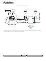
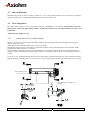
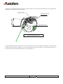
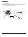
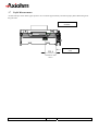
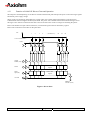
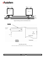
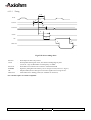
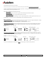
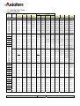
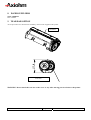
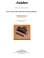
THERMAL PRINTER COMPONENTS ELECTRON PRINTER MECHANISM SERIES USER MANUAL ELECTRON Reference 31 08 307 Issue Z February 2005 AXIOHM 1 rue d'Arcueil - BP 820 92542 MONTROUGE Cedex Tel : (33) 1 58 07 17 17, Fax : (33) 1 58 07 17 18 www.axiohm.com EVOLUTIONS Date 02/2005 Issue Z Modifications Creation ELECTRON Printer Mechanism Series User manual page 1/42 Reference: FDE 3108307 Issue Z IMPORTANT This manual contains the basic instructions for printer operation. Read it carefully before printer use, paying special attention to the "Recommendations" section. ELECTRON Printer Mechanism Series User manual page 2/42 Reference: FDE 3108307 Issue Z CONTENTS 1 UNPACKING ......................................................................................... 5 2 OVERVIEW ........................................................................................... 5 3 MECHANICAL SPECIFICATIONS................................................... 7 3.1 General Description ............................................................................................ 7 3.2 External Dimensions........................................................................................... 8 3.3 Fixing Elements ................................................................................................ 10 Clip Mounting .................................................................................. 10 3.5 Chassis Mounting.............................................................................................. 11 3.6 Cover Integration .............................................................................................. 11 3.6.1 Information for Cover Dimensioning............................................... 11 3.6.2 Hinge Positioning ............................................................................. 14 Useful Measurements........................................................................................ 15 ELECTRICAL SPECIFICATIONS................................................... 16 4.1 Nominal Power Supply...................................................................................... 16 4.2 Nominal Consumption of Printer ..................................................................... 16 4.3 Description of Print Head ................................................................................. 16 4.5 6 3.3.2 Flex Cable Position ........................................................................................... 10 4.4 5 Screw Mounting ............................................................................... 10 3.4 3.7 4 3.3.1 4.3.1 Function of 64 bit LSI Drivers Chart and Operation........................ 17 4.3.2 Electrical Specifications of 64-BIT LSI Driver................................ 19 4.3.3 Print Head Connection..................................................................... 22 Bipolar Stepping Motor..................................................................................... 23 4.4.1 Characteristics ................................................................................. 23 4.4.2 Motor Connection ............................................................................ 23 4.4.3 Induction Sequence and Timing (paper feed) .................................. 24 4.4.4 Printing Mode .................................................................................. 24 Sensor Specifications ........................................................................................ 25 4.5.1 End of Paper Opto-sensor................................................................ 25 4.5.2 Recommended Use for Opto-sensor ................................................. 26 PRINTER CONTROL TECHNIQUES ............................................. 27 5.1 Mode 1 ............................................................................................................... 27 5.2 Mode 2 ............................................................................................................... 29 5.3 Mode 3 ............................................................................................................... 30 RECOMMENDATIONS ..................................................................... 31 6.1 Mechanical Recommendations ......................................................................... 31 6.2 Electrical Recommendations............................................................................. 35 6.3 Motor Driving Recommendations..................................................................... 35 ELECTRON Printer Mechanism Series User manual page 3/42 Reference: FDE 3108307 Issue Z 7 HEATING TIME CALCULATIONS ................................................ 36 7.1 Real Heating Times ........................................................................................... 36 7.2 Historical Control.............................................................................................. 37 7.3 Heating Time Table........................................................................................... 39 7.4 Thermistor Specifications ................................................................................. 40 8 PAPER SUPPLIERS............................................................................ 41 9 TEAR BAR OPTION........................................................................... 41 ELECTRON Printer Mechanism Series User manual page 4/42 Reference: FDE 3108307 Issue Z 1 UNPACKING Each printer mechanism is packaged in an antistatic bag. Observe precautions while handling in electrostatic protected areas. 2 OVERVIEW UL 60950 CSA 22.2 - 60950 / Project n°04CA45602 This printer is designed for the use of a clamshell cover, a latch if required, and an optional tear bar. SUMMARY OF PRINTER SPECIFICATIONS ITEM VALUE UNITS Static thermal dot line printing - 48 mm see "heating time": depends on voltage, temperature and control way mm/sec Paper loading Clamshell - Paper width 58 (+0, -1) mm 60 g/m2 JUJO AF50KSE3 - Number of resistor dots 384 - Maximum number of dots energized simultaneously 128* - 8 dots/mm 2 motor steps 0.125 By thermistor By opto-sensor mm - 58 mm Print method Print width Maximum print speed Maximum paper thickness Recommended paper Resolution Paper feed pitch Head temperature detection Out of paper detection Maximum size for the roll paper - *: The printing density variation may become significant when the number of dots energized simultaneously becomes greater than 64. Print head is allowed to have 4.0A maximum. ELECTRON Printer Mechanism Series User manual page 5/42 Reference: FDE 3108307 Issue Z SUMMARY OF PRINTER SPECIFICATIONS (continued) ITEM VALUE UNITS 21 % - 25 to + 70 °C Operating temperature range 0 to +50 °C Relative humidity (operating) 10 to 90 % Operating voltage range Vcc (logic) 2.7 to 5.5 V DC 4 to 8.5 V DC 0.23 MJ/dot Current consumption: Vch (at nominal value: 5V) 38 mA per resistor dot «on» Current consumption: Icc max (at value : 5V) 24 mA Current consumption: Stepping motor (at nominal value) 277 Maximum duty cycle (1 sec “on” max) Storage temperature range Operating voltage range Vch (dot) Energy Supply per activated phase 1. 108 pulses 50 km Height 26.3 mm Width 68.6 mm Depth 30 mm Electrical life time** Mechanical life time ** Over all dimensions ***: mA Weight 32 g **: Per AXIOHM standard test conditions (which are mainly: 5V, ≈ 25 °C, dot printing duty cycle = 30%) ***: Note: general tolerances ± 0.2 (when no other is specified) ELECTRON Printer Mechanism Series User manual page 6/42 Reference: FDE 3108307 Issue Z 3 MECHANICAL SPECIFICATIONS 3.1 General Description This mechanism consists of: - Plastic chassis - Stepper motor - Gears train - Print head module with flex cable and opto sensor - Platen roller ELECTRON Printer Mechanism Series User manual page 7/42 Reference: FDE 3108307 Issue Z 3.2 External Dimensions Locating Points Central fixing point 2 back fixing points 2 fixing points Paper path MAX TOP VIEW 2 front clips ELECTRON Printer Mechanism Series User manual page 8/42 Reference: FDE 3108307 Issue Z Mechanical views (continued) SIDE VIEW BACK VIEW PRINT SIDE PAPER EXIT 65° Mounting Plane PAPER ENTRANCE 26 points Connector, 1mm pitch The printed ticket exits at 65° in comparison to the mounting plane. The paper entrance into the mechanism can be made according to angles of 0° to 90° as compared to the mounting plane. ELECTRON Printer Mechanism Series User manual page 9/42 Reference: FDE 3108307 Issue Z 3.3 Fixing Elements 3.3.1 Screw Mounting There are two possible ways to mount the print mechanism using screws. a) _ Central Screwing, by a Ø3mm auto-tapping plastic screw in Fix-1. Positioning by an axis of locating Loc-1 of Ø2mm (see diagrams on the following pages). b) _ Using the screw mounts at the back of the mechanism: Either mount from below with two Ø2,5mm auto-tapping plastic screws in the printer frame at FIX-2 and FIX-3. If it is chosen to mount at the back of the mechanism, one must use the front clipping zones, at CLIP-1 and CLIP-2. **Warning: The auto-tapping plastic screws should have a net point angle of 30°.** 3.3.2 Clip Mounting There are four clipping points on this printer mechanism CLIP-1, CLIP-2, CLIP-3 and CLIP-4 (see drawings on the next page). 3.4 Flex Cable Position Connections are done via unique flex cable containing all electrical functions of the printer (thermal head, motor rand opto-sensor). The flex cable is to be connected on a 26 pin connector with a 1mm pitch. The connector can be located at the back of the printer (horizontal connection) or below the printer (vertical connection) or in another intermediate position. WARNING: Do not put any constraint on the flex cable during integration or while connecting. DO NOT FORCE THE FLEX IN TRACTION HORIZONTAL CONNECTOR BEHIND EXAMPLE OF A CONNECTOR IN INTERMEDIATE POSITION VERTICAL CONNECTOR BELOW AREA OF INTERMEDIATE POSITION ELECTRON Printer Mechanism Series User manual page 10/42 Reference: FDE 3108307 Issue Z 3.5 Chassis Mounting Mounting hole position is shown on figure in chapter 3.2. Use 3 x M2.5 self threading screws pan head eco-syn length 6 mm (for example from our supplier BOSSARD) for the 3 diameters Ø2,2 ± 0.05. 3.6 Cover Integration The "ELECTRON" printer can only accept paper loading by "CLAMSHELL" cover design. As the printer as not been design for the “auto-load” paper feature, contact Axiohm representatives for more information if you want to use it in this mode. Axiohm does not supply the cover. 3.6.1 Information for Cover Dimensioning The cover is essential. It must maintain the platen and allow the positioning within the printer frame ensuring good rotation of the cover itself. These drawings show the dimensions necessary for cover design. The length of the silicone part of the platen is a maximum of 52mm. The 58.11mm dimension is the maximum width allowed in the frame where the cover slides in. Forks maintaining the platen must have a maximum thickness of 2.55mm and be made out of a material that supports clipping on axis, by deforming oblong shape and opening or closing effort of the cover that we measured to be of 10.3N average For the cover, we recommend oblong shapes (see below drawings) to maintain the platen axle. These shapes must allow a light translation of the platen in the cover in order not to force positioning and rotating of the platen when cover is closed. MOUNTING PLANE Two openings for eventual cover clipping PLATEN PLATEN AXLE ELECTRON Printer Mechanism Series User manual page 11/42 Reference: FDE 3108307 Issue Z That is an example of a possible cover: FFOR THE PLATEN’S GROOVE ELECTRON Printer Mechanism Series User manual page 12/42 Reference: FDE 3108307 Issue Z The angle of the oblong shape where the platen is located on the cover must be in the range between five (5) degrees and 15 degrees as compared to the mounting plane. PLATEN AXLE POSSIBLE HOLES FOR COVER MOUNTING PLANE COVER FORM GIVEN FOR We also designed special circular holes on each side of the frame to allow cover clipping from inside or outside the printer mechanism. Those holes have a diameter of 3,5mm and their highest point is located at 12,1mm from the fixing plane of the printer and at 7,2mm from the platen axle. (see drawings page 11) ELECTRON Printer Mechanism Series User manual page 13/42 Reference: FDE 3108307 Issue Z 3.6.2 Hinge Positioning The zone where the hinge is located must be between 2 planes passing on the platen axis with a 25° maximum angle. The superior plane must not be inclined of less than 5° from the mounting plane. Therefore, the inferior plane must not be inclined more than 30°from the mounting plane (see below drawings). PLATEN AXLE PRINT MODULE HINGE AXLE MOUNTING PLANE Acceptable zone for the hinge CENTER OF MODULE HINGE AXLE Note : PLAN PASSANT PAR L’AXE DE CABESTAN = PLANE PASSING BY PLATEN AXLE ELECTRON Printer Mechanism Series User manual page 14/42 Reference: FDE 3108307 Issue Z 3.7 Useful Measurements An infra-red opto sensor detects paper presence. It is located at approximately one third of paper path width starting from the gears side. TOP VIEW WITHOUT PLATEN LIMIT OF PAPER PATH CENTER OF THE OPTO ELECTRON Printer Mechanism Series User manual page 15/42 Reference: FDE 3108307 Issue Z 4 ELECTRICAL SPECIFICATIONS 4.1 Nominal Power Supply Print head: Logic (Vcc) Value 3.3 / 5 Units V DC Dot line 4 to 8.5 - 4 to 8.5 - Stepping motor 4.2 Nominal Consumption of Printer Print head: Heating current / dot (Vch) Value 38 Units mA Logic current (Vcc) All high 24 mA Stepping motor current (2 activated phases) 554 mA 4.3 Description of Print Head Value UNIT 6 - 2.7 to 5.5 *1 V DC Mean dot resistance (± 4%) 130 Ω Nominal dot supply voltage 5 (min = 4, max = 8.5) V DC 38*2 mA Driver chips Operating range (Vcc) Nominal Heating current per dot ( at 5V) *1 Filter any transient signal and parasitic on this line. Separate Vcc from Vch because Vch can go lower than 4.75 Volts. Vcc must be connected to the same power supply than the other electronic circuits which drive the printer. *2 The print density variation may become significant when the number of dots energized simultaneously becomes greater than 64 ELECTRON Printer Mechanism Series User manual page 16/42 Reference: FDE 3108307 Issue Z 4.3.1 Function of 64 bit LSI Drivers Chart and Operation The LSI power and multiplexing circuit drivers located on the thermal print head provide power control from logic signals and the DC power supply voltage. These circuits are supplied by 3.3 or 5 V logic voltage. Take care to filter transient and parasitic on all logic lines. Undetermined states can happen and destroy the head. The power source should be disconnected from the logic source. The logic source must be connected to the same source as the electronic circuits in charge of controlling the printer. Each circuit features 64 open collector transistors, a 64-bit shift register and a 64-bit memory register. Each circuit controls 64 resistor dots on the print head. Vch 1 2 3 4 ...... (OUTPUTS).... 62 63 64 Line of resistor dots GND Output Enable (OE) Strobe 64 bits buffer register Serial Input (SI) 64 bits shift register CLOCK SERIAL OUTPUT (SO) Figure 1 driver chart ELECTRON Printer Mechanism Series User manual page 17/42 Reference: FDE 3108307 Issue Z R64 Resistors R1 R64 CHIP n SI R1 Resistors CHIP n+1 SO SI SO OUT IN CLK Strobe OE n OE n+1 Figure 2 Routing of data to the thermistor dots Line of dots Print head substrate paper path direction Data input Fig.3 Dots print order The first bit of data entered will be the first bit of data printed (FIFO). ELECTRON Printer Mechanism Series User manual page 18/42 Reference: FDE 3108307 Issue Z 4.3.2 4.3.2.1 Electrical Specifications of 64-BIT LSI Driver General Electrical Description of Drivers Description of drivers MIN MAX 8.5 UNIT Volt Vcc Volt Max output current 40 mA Total max output current (64 dots "On") 2.6 A Max leakage current/driver when stand-by mode 10 µA Max voltage at outputs 1 to 64 Max voltage any other pin 4.3.2.2 Other The specifications given below are given for the following conditions: Logic voltage on chip: 3.3 V < Vcc < 5.5V (care should be taken to filter any transient signal or parasitic in order to keep the driver in a known state: failure to observe this may result in head destruction) Clock frequency (max.): Logic Current (5 V) 8 MHz (Vcc=5V) 5 MHz (Vcc=3.3V) Min high-level input voltage Conditions Vcc = 5 V Values 0.8 x Vcc Symbol Vih Max high-level input voltage Vcc = 5 V Vcc Vih Min low-level input voltage 0 Vil Max low-level input voltage 0.2 x Vcc Vil Max high-level input current Vih = Vcc 0.5µA Iih Max. low-level input current Vil = 0 0.5µA Iil Min. high-level output voltage 4.45 V Voh Max. low-level output voltage 0.05 V Vol ELECTRON Printer Mechanism Series User manual page 19/42 Reference: FDE 3108307 Issue Z 4.3.2.3 Timing Tclk Clock t2 t3 Serial in t4 Serial out t5 Strobe t7 OE t9 t9 Data Out : Fig.4 LSI driver timing chart Serial in Clock : : Serial out STROBE OE Data Out n : : : : Serial input for data to be printed. Serial/parallel shift register clock, activated on leading edge of pulse (rest level = logic 0) Maximum clock frequency is 8 MHz. Serial data out sent back to the connector of the thermal head Signal for putting data into memory, active on logic level 0 (rest level = logic 1). Output Enable (OE1 to OE6) power activation signals active at logic level 1. Internal data out to heating points (not available on connector). Note: All these inputs are CMOS compatible. ELECTRON Printer Mechanism Series User manual page 20/42 Reference: FDE 3108307 Issue Z Fig. 5 LSI driver symbols 5V / 8 MHz (Max) Symbol Description Min 45 Maxi 2.7~ 4.5 V/ 5MHz (Max) Min 64 Maxi Unit ns Tclk Clock pulse width t2 Clock - SI set-up time 30 40 ns t3 Clock – SI hold time 10 10 ns 95 160 ns t4 Serial out delay time t5 Clock – strobe set up time 70 150 ns t7 Strobe pulse width 50 100 ns t9 OE data out delay time 6 15 µs Vcc = 5V or 3.3V, Temp = 25 °C with resistive load ELECTRON Printer Mechanism Series User manual page 21/42 Reference: FDE 3108307 Issue Z 4.3.3 Print Head Connection Pinout of the print head flex cable Pin Number 1 2 3 4 5 6 7 8 9 10 11 12 13 14 15 16 17 18 19 20 21 22 23 24 25 26 Signal B1 A0 A1 B0 Anode opto GND Collector opto Vch Vch Data-out STROBE GND GND OE1 Thermistor1 Thermistor2 Vdd OE2 GND GND CLOCK Data-in Vch Vch Gnd for ESD Gnd for ESD Comment Paper feed motor B1 Paper feed motor A0 Paper feed motor A1 Paper feed motor B0 Anode of en of paper opto-sensor GND Collector of end of paper opto-sensor Vch Vch Data out Strobe signal for line print GND GND OE for drivers 1,2,3 Thermistor1 Thermistor2 Vdd OE for drivers 4,5,6 GND GND Clock signal for serialising data to line Data input Vch Vch Ground for ESD evacuation Ground for ESD evacuation AXIOHM Contact side 1 26 Thickness: 300 µ For the connection of the mechanism Axiohm recommend the following 26 pins connectors (from print head flex to board): - JST Ref 26 FMN-BTRK-A Molex Ref :52806-2610 - JST Ref 26 FMZ-BT Molex Ref : 71226-2635 ELECTRON Printer Mechanism Series User manual page 22/42 Reference: FDE 3108307 Issue Z - 4.4 Bipolar Stepping Motor This motor is used to drive the platen for paper feeding. It is a bipolar stepping motor and its characteristics are described bellow. 4.4.1 Characteristics Recommended control voltage (voltage range: 4 to 8.5V) 5 VDC Coil Resistance 18 Ω 2 (bipolar) Number of phases Pitch angle 18° Number of steps per revolution 20 0.125 Mm 277 (=5V/18Ω) 720 (=45mm/s) mA/phase Paper feed for 2 motor steps Recommended control current Maximum starting speed * step/s * to go faster : an acceleration ramp up must be achieved. For the motor driving, see the following page and the chapter "Recommendations" 4.4.2 Motor Connection The motor is connected to the main flex cable in addition to the End of paper opto sensor. See 4.3.3 Print head connection ELECTRON Printer Mechanism Series User manual page 23/42 Reference: FDE 3108307 Issue Z 4.4.3 Induction Sequence and Timing (paper feed) Motor feed timing diagram t1 IP1 t2 IP2 Motor Steps Heating cycles Note that each time the motor has been stopped for more than 8 ms the next step should be longer by 1 ms in order to restart the motor in the appropriate position. Motor initialisation: This operation is necessary to place the motor in a good position when the printer electronic is powered on or reset. Both phases must be powered with the same current during t1=1 ms. It must be followed by 16 motor steps in order to compensate the play in the gears. 4.4.4 Printing Mode There are 4 different positions for the motor phases. The circulation is: P1 = A0B0; P2 = A1B1 __ __ _ __ P1P2 ÖP1P2 ÖP1P2 ÖP1P2 ÖP1P2 The position of the phases must be kept in memory while the phase currents are switched to zero in order to restart the motor in a good position. IP = ± 277 mA t2 > 1.3 ms During printing, the motor phases should be maintained. Otherwise, a paper motion can occur and induce unevenly spaced sub lines. A good way to achieve this without over heating the motor is to keep the motor phases "on" when the buffer contains data, and to release them when the buffer is empty. ELECTRON Printer Mechanism Series User manual page 24/42 Reference: FDE 3108307 Issue Z 4.5 Sensor Specifications 4.5.1 End of Paper Opto-sensor This opto-sensor detects the end of paper 4.5.1.1 Electrical Characteristics Absolute maximum ratings IF (mA) VR (V) 50* 5 PD(mW) 70 VCEO(V) 20 IC(mA) 20 Operating characteristics VF (V) IR (µA) ICEO (A) Value Maxi 1.6 Maxi 10 Maxi 2.10-7 IC (mA) VCE(sat)(v) Mini 80 µA / Max 0.5 Maxi 1100 µA Conditions IF = 10 mA VR = 5 V VCEO = 10V PC(mW) 70 IF = 10 mA IF = 10 mA VCE = 5 V IC = 50 µA tr (µs) Typical 5 IC = 1 mA RL = 100 Ω VCC = 5V * : Axiohm advise to pulse it 4.5.1.2 Connection Integrated with the main flex cable, see 4.3.3 ELECTRON Printer Mechanism Series User manual page 25/42 Reference: FDE 3108307 Issue Z 4.5.2 Recommended Use for Opto-sensor The user should be aware that the opto-sensor characteristics have very wide tolerances. Thus, we recommend the use of the schematics below. 4.5.2.1 Opto Sensor: Sample Minimal External Circuit VCC(5V) PRINTER 47KΩ OPTO-SENSOR Vo if Condition: 9 For If = 20 mA .........Output signal is LOW when paper is PRESENT .........Output signal is HIGH when paper is EXHAUSTED Vo<0.7V. Vo>3.4V. 4.5.2.2 Sample external circuit with low consumption VCC(5V) VCC(5V) 10KΩ PRINTER OPTO--SENSOR µp output port BC807 47KΩ Vo 178Ω if Condition: 9 Pulse wave from output port with low level during 0.6 ms, measuring Vo 0.2 ms after pulse falling edge. 9 Same conditions for output signal Vo, as chapter above. ELECTRON Printer Mechanism Series User manual page 26/42 Reference: FDE 3108307 Issue Z 5 PRINTER CONTROL TECHNIQUES For printer control techniques, in order to operate the printer, we depict hereafter three possible modes. 5.1 Mode 1 The paper feeds itself automatically during the heating cycle, thereby permitting high speed to be achieved (in this mode, it is recommended to use historical control, see chapter: "Heating Time"). Printing of n dot line Transmission of data in series (Din) in step with CLK Transfer to memory stage (STROBE) Transmission of next series of data Heating controlled through OE 1,OE 2,...OEn simultaneously Motor feed 1 to n End of printing ELECTRON Printer Mechanism Series User manual page 27/42 Reference: FDE 3108307 Issue Z CLK T Din N Strobe OE 1 OEn Motor Steps T : Clock frequency 8 MHz maximum ( or 5 MHZ if VCC< 5V ) Timing diagram for mode 1 ELECTRON Printer Mechanism Series User manual page 28/42 Reference: FDE 3108307 Issue Z 5.2 Mode 2 The paper feed occurs after the heating cycle resulting in high quality printing. Printing of n dot line Transmission of data in series (Din) in step with CLK Transfer to memory stage (STROBE) Heating controlled through OE 1,OE 2,...OEn simultaneously Transmission of next series of data Motor feed 1 to n End of printing CLK T Din N Strobe OE 1 OEn Motor Steps T : Clock frequency 8 MHz maximum Timing diagram for mode 2 ELECTRON Printer Mechanism Series User manual page 29/42 Reference: FDE 3108307 Issue Z 5.3 Mode 3 This mode is used in conditions where there is a limit of electrical current. The dot line is printed in stages heating only a portion of the line at a time. This effectively gives a reduced power consumption. Printing of n dot line Transmission of data in series (Din) in step with CLK Transfer to memory stage (STROBE) Heating controlled through OE 1,OE 2,...OEn successively or in blocks Transmission of next series of data Motor feed 1 to n End of printing Clock CLK T Din (serial input) N N Strobe OE 1 OEn Motor Steps T : Clock frequency 8 MHz maximum Timing diagram for mode 3 ELECTRON Printer Mechanism Series User manual page 30/42 Reference: FDE 3108307 Issue Z 6 RECOMMENDATIONS 6.1 Mechanical Recommendations • Never apply mechanical stress to the printer; this could result in misalignment and thus degradation of the print quality. • The thermal print head must have 1 degree of freedom. Never prevent the print head from pivoting on its axis. • Refer to the drawings in chapters "Cover integration" to design an easy loading Clamshell cover. • The paper should be guided to the mechanism to make sure it is centred in the mechanism paper path (particularly when the paper width is less than 58mm). Flatness Support: • The « ELECTRON » printer must not be put in constraint during integration. For that, the support on which it is fixed must have a flatness of 0,15mm. During integration, the mounting plane can be tilted according to an indifferent angle of the horizontal. General Constraints of Integration : • The thermal head has a light oscillating movement around its axis during the opening or the closing of the cover. One must hold account for the integration and not place elements too close to the print head. • The unit’s surfaces for the integration must be situated in more than 0,5mm of the pieces in movement in the printer: gears printing head, spring of head, platen, except the oblong forms or "forks" to maintain the platen. If it is necessary, we can supply a plan or an IGES file for an example of the cover. ELECTRON Printer Mechanism Series User manual page 31/42 Reference: FDE 3108307 Issue Z Paper characteristics and paper guide • « ELECTRON » uses paper of 58mm maximum width and 68µm maximum thickness. The paper roll must not exceed 120g weight, corresponding to a diameter of approximately 60 mm rolled on a plastic roll of Ø16mm. Printing width is 48mm. To feed the paper to the printer we recommend guidance as close as possible to the entry of the printer mechanism forming a “tile effect”. PRINTER « TILE EFFECT » GUIDANCE OF PAPER • PAPER « ELECTRON » can not manage backward movement of paper. If printer is used in bi-station mode (2 parallel paper rolls printed simultaneously), there is no paper detection on the opposite side of the gears. If required, it will have to be integrated into the system bucket. Different Possibilities of Integration : • In a simple application : The paper loading of this mechanism uses a CLAMSHELL system. Our mechanism allows a simple application of the cover for a paper reservoir. No control lever is necessary for the opening of the cover. In the case that the lightness and the compactness of the customer’s application is most important, the cover can be reduced. The operator will act directly on the cover by pulling to open it. We advise a simple locking of the cover. There are places foreseen for that purpose on the walls of mechanism extremity (to see §2.1.) for the preservation of the cover during the manual cutting of the paper. Make sure that the cover does not deform itself during use. COVER PRINTER EXAMPLE OF LOCKING ELECTRON Printer Mechanism Series User manual page 32/42 Reference: FDE 3108307 Issue Z Two openings for eventual cover clipping • In an application with assistance in opening If necessary, help with the opening of the cover by pushbutton or lever can be necessary (see the figures below). EXAMPLE OF AN ACTUATOR AT THE BACK OF THE PRINTER ACTUATOR ARTICULATION OF THE SYSTEM TO HELP WITH OPENING HINGE OF THE COVER EXAMPLE OF ASSISTANCE WITH OPENING This help example of opening could be applied to a side of the cover, preferably the side with platen gears. Or, both sides of the cover by placing the actuator behind the hinge of cover or on the other side of the printer, not to obstruct the installation of the paper roller. Locking System : • Locking can be directly made on the printer (see above) or on some part of the customer application. ELECTRON Printer Mechanism Series User manual page 33/42 Reference: FDE 3108307 Issue Z ARTICULATION OF THE LOCKING SYSTEM HINGE OF THE LID EXAMPLE OF LOCKING HINGE OF THE LID EXAMPLE OF LOCKING ELECTRON Printer Mechanism Series User manual page 34/42 Reference: FDE 3108307 Issue Z 6.2 Electrical Recommendations When energising the thermal print head, it is important to apply the logic supply voltage first and the print head supply voltage next. If the line of dots is supplied before the control logic, resistor dots may be destroyed. Because the control logic has a random state, resistors might be heated for a longer period than the specified maximum, burning out the heated resistor. To avoid this, we recommend applying the heating voltage (Vch) after the logic supply voltage (Vcc, 5V). The same precaution should be taken when shutting down. The supply voltage Vch must be switched off before the logic supply voltage Vcc. Care should be taken to allow enough time for residual capacitive charge to dissipate. 6.3 Motor Driving Recommendations * Motor driving can be achieved with voltage control or regulated current control. When the motor is under voltage control, it is recommended to connect it to the same supply as logic current (from 2.7V to 5.5V). If the motor is connected to the heating source power, it is recommended to control it under regulated current. When the control voltage is greater than 5.25 V, or the current is greater than 280 mA per phase, it is necessary to determine a duty cycle time (max recommended: 21% ton/toff, with a sec “on” max) to avoid the motor temperature rising. This has to be achieved with the customer host chassis, as the cooling depends on air volume and circulation around the motor. This motor can be controlled either under voltage or current. The maximum voltage is 8.5 V, the maximum current is 470 mA per phase. The maximum temperature on the external motor frame is 80°C. ELECTRON Printer Mechanism Series User manual page 35/42 Reference: FDE 3108307 Issue Z 7 HEATING TIME CALCULATIONS 7.1 Real Heating Times Density vs Energy At Nominal Speed & Nominal Temperature t 1= Rmean × E 0 V '2 6 Volts Voltage Temperature 23 °C 50 mm/s Speed AF50KSE3 Paper 0,31 mJ (cf Density Sheet) Eo saturation Tch (saturation heating time 1,120 ms Température statique 80 °C Heating Time vs Speed At Nominal Voltage & Nominal Temperature t 2 = t1 × ( a × Log ( tm ) + b ) Voltage Temperature Paper Coeff "a" Coeff "b" 6 Volts 23 °C AF50KSE3 0,4071 0,6269 Heating Time vs Temperature tm = Time for motor step (ms) At Nominal Speed & Nominal Voltage For linear modelisation Voltage Speed Paper Coeff "c" Coeff "d" Coeff "g" Coeff "h" Coeff "i" Coeff "j" Temperature Speed Paper Coeff "e" Coeff "f" 6 Volts 50 mm/s AF50KSE3 -0,01420000 1,32660000 -0,00000477 0,00050244 -0,02740654 1,42268041 Heating Time vs Voltage 23 °C 50 mm/s AF50KSE3 0,9490 0,3100 ELECTRON Printer Mechanism Series User manual t 3 = t 2 × ( cT + d ) For polynomial modelisation t3 = t2 × ( g × T3 + hT2 × iT + J) At nominal Temperature & Speed V ' = eV + f page 36/42 Reference: FDE 3108307 Issue Z 7.2 Historical Control The history coefficient depends on the speed (explained below). It gives the reduction (in %) of the TCH (nominal heating time), which has to be applied on a dot previously heated (on N1). Paper feed motor control parameters: mm/sec mm/sec Min Speed = 15 Max Speed = 71 Ramp Size = 8 Speed = MIN_SPEED + (MAX_SPEED – MIN_SPEED) x Index / (RAMP_SIZE-1) History control : Tb = (COEFA x ln(6.25) + COEFB) Tb = 1,716 TbTmp = (COEFA x ln(StepTime/1000) + COEFB) HistTmp = 100 x (Tb-TbTmp) / Tb if (HistTmp < 0) HistCoef = 0 else HistCoef = HistTmp Index 0 1 2 3 4 5 6 7 Step Time (µs) 8332 5434 4020 3204 2657 2272 1984 1760 Speed (mm/sec) 15 23 31 39 47 55 63 71 History Coef (%) 0 4 13 19 25 30 34 37 ELECTRON Printer Mechanism Series User manual History control Raster (N) 1 Raster (N-1) 0 1 0 1 1 1 1 1 1 1 HistoryEn 0 Actual heating time = TCH x (1 – HistoryCoef x HistoryEn) page 37/42 Reference: FDE 3108307 Issue Z The Heating time table is given on next page. The motor cycle time for one dot line is given in the second top line of the table; it is the time for two motor steps. Column 3 (indicated with: speed <20 mm/s, and motor cycle time > 6.25 ms) gives the required heating time, giving the necessary energy to obtain an optical density of 1.2. Three areas are then defined in the heating time table: Area 1: “white” The motor cycle time for one dot line is greater than the heating time indicated in column 3. Area 2: “grey area” The heating time in column 3 is greater than the motor cycle time. Area 3: “bold numbers” The indicated heating time (depending on speed, voltage and temperature) would be greater than the motor cycle time. In areas 1 and 2, the heating time can be controlled either with or without historical control. How to use the tables: Without historical control: apply the indicated heating time given as a function of speed, voltage and temperature. At high speed, printing quality for isolated dots might be affected with this method. Example: at 20 mm/s, 30°C and 6 volts, heating time = 1.418 ms (time from column 3). With historical control in area 1: apply the indicated heating time (function of speed, voltage and temperature) when the dot has been heated on the previous dot line, and the time from column 3 when it has not. This method gives the best printing quality. Example: at 50 mm/s, 20°C and 6 volts: previous dot dot to heat Heating time to apply dot ON 1,160 ms dot OFF 1.592 ms With historical control in area 2: apply the indicated heating time (function of speed, voltage and temperature) when the dot has been heated on the previous dot line, and the motor cycle time when it has not. At high speed, printing quality for isolated dots might be slightly affected with this method. Example: at 100 mm/s, 25°C and 5 volts: previous dot dot to heat Heating time to apply dot ON 1,106 ms dot OFF 1.250 ms We do not recommend the use of the printer in area 3 as the pint quality would be seriously affected. ELECTRON Printer Mechanism Series User manual page 38/42 Reference: FDE 3108307 Issue Z 7.3 Heating Time Table With Paper AF50KSE3 Voltage (V) Temp (°C) Real Motor time for an under line 4,00 Volts 0 °C 4,00 Volts 10 °C 4,00 Volts 20 °C 4,00 Volts 25 °C 4,00 Volts 30 °C 4,00 Volts 40 °C 4,00 Volts 50 °C 5,00 Volts 0 °C 5,00 Volts 10 °C 5,00 Volts 20 °C 5,00 Volts 25 °C 5,00 Volts 30 °C 5,00 Volts 40 °C 5,00 Volts 50 °C 6,00 Volts 0 °C 6,00 Volts 10 °C 6,00 Volts 20 °C 6,00 Volts 25 °C 6,00 Volts 30 °C 6,00 Volts 40 °C 6,00 Volts 50 °C 7,00 Volts 0 °C 7,00 Volts 10 °C 7,00 Volts 20 °C 7,00 Volts 25 °C 7,00 Volts 30 °C 7,00 Volts 40 °C 7,00 Volts 50 °C 8,00 Volts 0 °C 8,00 Volts 10 °C 8,00 Volts 20 °C 8,00 Volts 25 °C 8,00 Volts 30 °C 8,00 Volts 40 °C 8,00 Volts 50 °C Speed (mm/s) R= 130 Ohms < 20 mm/s 30 mm/s 35 mm/s 40 mm/s 50 mm/s 56 mm/s 60 mm/s 65 mm/s 70 mm/s 80 mm/s 90 mm/s 100 mm/s 6,250 ms 4,170 ms 3,570 ms 3,130 ms 2,500 ms 2,230 ms 2,080 ms 1,920 ms 1,790 ms 1,560 ms 1,390 ms 1,250 ms 4,669 ms 4,109 ms 3,894 ms 3,712 ms 3,401 ms 3,243 ms 3,146 ms 3,035 ms 2,938 ms 2,748 ms 2,588 ms 2,441 ms 3,919 ms 3,449 ms 3,268 ms 3,116 ms 2,854 ms 2,722 ms 2,641 ms 2,548 ms 2,466 ms 2,306 ms 2,172 ms 2,049 ms 3,405 ms 2,996 ms 2,839 ms 2,707 ms 2,480 ms 2,364 ms 2,294 ms 2,213 ms 2,142 ms 2,004 ms 1,887 ms 1,780 ms 3,207 ms 2,822 ms 2,674 ms 2,549 ms 2,335 ms 2,227 ms 2,160 ms 2,084 ms 2,018 ms 1,887 ms 1,777 ms 1,676 ms 3,032 ms 2,668 ms 2,529 ms 2,410 ms 2,208 ms 2,105 ms 2,043 ms 1,971 ms 1,908 ms 1,784 ms 1,681 ms 1,585 ms 2,707 ms 2,382 ms 2,258 ms 2,152 ms 1,972 ms 1,880 ms 1,824 ms 1,760 ms 1,704 ms 1,593 ms 1,500 ms 1,415 ms 2,336 ms 2,056 ms 1,948 ms 1,857 ms 1,702 ms 1,622 ms 1,574 ms 1,519 ms 1,470 ms 1,375 ms 1,295 ms 1,221 ms 3,081 ms 2,711 ms 2,569 ms 2,449 ms 2,244 ms 2,139 ms 2,076 ms 2,003 ms 1,939 ms 1,813 ms 1,707 ms 1,611 ms 2,586 ms 2,275 ms 2,156 ms 2,056 ms 1,883 ms 1,796 ms 1,742 ms 1,681 ms 1,627 ms 1,522 ms 1,433 ms 1,352 ms 2,246 ms 1,977 ms 1,873 ms 1,786 ms 1,636 ms 1,560 ms 1,513 ms 1,460 ms 1,413 ms 1,322 ms 1,245 ms 1,174 ms 2,116 ms 1,862 ms 1,764 ms 1,682 ms 1,541 ms 1,469 ms 1,425 ms 1,375 ms 1,331 ms 1,245 ms 1,173 ms 1,106 ms 2,000 ms 1,760 ms 1,668 ms 1,590 ms 1,457 ms 1,389 ms 1,348 ms 1,300 ms 1,259 ms 1,177 ms 1,109 ms 1,046 ms 1,786 ms 1,572 ms 1,490 ms 1,420 ms 1,301 ms 1,240 ms 1,203 ms 1,161 ms 1,124 ms 1,051 ms 0,990 ms 0,934 ms 1,541 ms 1,356 ms 1,285 ms 1,225 ms 1,123 ms 1,070 ms 1,039 ms 1,002 ms 0,970 ms 0,907 ms 0,854 ms 0,806 ms 2,184 ms 1,922 ms 1,821 ms 1,736 ms 1,590 ms 1,516 ms 1,471 ms 1,420 ms 1,374 ms 1,285 ms 1,210 ms 1,142 ms 1,833 ms 1,613 ms 1,529 ms 1,457 ms 1,335 ms 1,273 ms 1,235 ms 1,191 ms 1,153 ms 1,079 ms 1,016 ms 0,958 ms 1,592 ms 1,401 ms 1,328 ms 1,266 ms 1,160 ms 1,106 ms 1,073 ms 1,035 ms 1,002 ms 0,937 ms 0,883 ms 0,832 ms 1,500 ms 1,320 ms 1,251 ms 1,192 ms 1,092 ms 1,041 ms 1,010 ms 0,975 ms 0,944 ms 0,882 ms 0,831 ms 0,784 ms 1,418 ms 1,248 ms 1,183 ms 1,127 ms 1,033 ms 0,985 ms 0,955 ms 0,922 ms 0,892 ms 0,834 ms 0,786 ms 0,741 ms 1,266 ms 1,114 ms 1,056 ms 1,007 ms 0,922 ms 0,879 ms 0,853 ms 0,823 ms 0,797 ms 0,745 ms 0,702 ms 0,662 ms 1,093 ms 0,962 ms 0,911 ms 0,869 ms 0,796 ms 0,759 ms 0,736 ms 0,710 ms 0,688 ms 0,643 ms 0,606 ms 0,571 ms 1,628 ms 1,433 ms 1,358 ms 1,294 ms 1,186 ms 1,131 ms 1,097 ms 1,058 ms 1,025 ms 0,958 ms 0,903 ms 0,851 ms 1,367 ms 1,203 ms 1,140 ms 1,086 ms 0,995 ms 0,949 ms 0,921 ms 0,888 ms 0,860 ms 0,804 ms 0,758 ms 0,714 ms 1,187 ms 1,045 ms 0,990 ms 0,944 ms 0,865 ms 0,824 ms 0,800 ms 0,772 ms 0,747 ms 0,699 ms 0,658 ms 0,621 ms 1,118 ms 0,984 ms 0,933 ms 0,889 ms 0,814 ms 0,777 ms 0,753 ms 0,727 ms 0,704 ms 0,658 ms 0,620 ms 0,585 ms 1,057 ms 0,931 ms 0,882 ms 0,841 ms 0,770 ms 0,734 ms 0,712 ms 0,687 ms 0,665 ms 0,622 ms 0,586 ms 0,553 ms 0,944 ms 0,831 ms 0,787 ms 0,751 ms 0,688 ms 0,656 ms 0,636 ms 0,614 ms 0,594 ms 0,556 ms 0,523 ms 0,494 ms 0,815 ms 0,717 ms 0,679 ms 0,648 ms 0,593 ms 0,566 ms 0,549 ms 0,530 ms 0,513 ms 0,479 ms 0,452 ms 0,426 ms 1,261 ms 1,109 ms 1,051 ms 1,002 ms 0,918 ms 0,875 ms 0,849 ms 0,820 ms 0,793 ms 0,742 ms 0,699 ms 0,659 ms 1,058 ms 0,931 ms 0,882 ms 0,841 ms 0,771 ms 0,735 ms 0,713 ms 0,688 ms 0,666 ms 0,623 ms 0,586 ms 0,553 ms 0,919 ms 0,809 ms 0,767 ms 0,731 ms 0,670 ms 0,638 ms 0,619 ms 0,598 ms 0,578 ms 0,541 ms 0,509 ms 0,481 ms 0,866 ms 0,762 ms 0,722 ms 0,688 ms 0,631 ms 0,601 ms 0,583 ms 0,563 ms 0,545 ms 0,509 ms 0,480 ms 0,453 ms 0,819 ms 0,720 ms 0,683 ms 0,651 ms 0,596 ms 0,568 ms 0,552 ms 0,532 ms 0,515 ms 0,482 ms 0,454 ms 0,428 ms 0,731 ms 0,643 ms 0,610 ms 0,581 ms 0,532 ms 0,508 ms 0,492 ms 0,475 ms 0,460 ms 0,430 ms 0,405 ms 0,382 ms 0,631 ms 0,555 ms 0,526 ms 0,501 ms 0,459 ms 0,438 ms 0,425 ms 0,410 ms 0,397 ms 0,371 ms 0,350 ms 0,330 ms ELECTRON Printer Mechanism Series User manual page 39/42 Reference: FDE 3108307 Issue Z 7.4 Thermistor Specifications Operating Temperature: - 20 to + 80 °C Thermistor time constant: 5 sec (at 25°C) Dissipation constant: 0.9 mW/°C Maximum power: 4.5 mW (at 25°C) This thermistor has a rated value of 30 kΩ ± 5 %. Its resistance variation can be expressed as follows: 1 R = Rn exp (B ( T 1 ) ) where T is in Kelvin degrees (K). This gives the following curve (for T in °K) Tn (T(°K) = 273.15 (°K) + each temperature (°C) B = 3950 K ± 2% Rn = reference value at temperature Tn (298° K) kΩ 200 180 160 140 120 100 80 60 40 20 0 -20 -10 0 10 20 ELECTRON Printer Mechanism Series User manual 30 40 page 40/42 50 60 °C 70 80 Reference: FDE 3108307 Issue Z 8 PAPER SUPPLIERS JUJO AF50KSE3 Ref: 3104208 9 TEAR BAR OPTION As an option there is a metal tear bar assembly, which can be clipped on this printer. TEAR BAR OVERALL HEIGHT WITH THE TEAR BAR WARNING: Do not attach the tear bar on the cover or any other moving part in relation to the printer. ELECTRON Printer Mechanism Series User manual page 41/42 Reference: FDE 3108307 Issue Z MAXIMUM ANGLE TO CUT THE PAPER MOUNTING PLAN PAPER ENTRY To cut paper with the tear bar, it is important to draw the paper according to an angle lower than 45° as compared to the mounting plane. Otherwise, the platen is likely to be ejected. ELECTRON Printer Mechanism Series User manual page 42/42 Reference: FDE 3108307 Issue Z