1
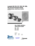
LPA2-AZ2
MODBUS
ATEX Fluid Condition Monitors
User Guide
www.mpfiltri.co.uk
200.160-EN
Document Revision 18.2
1 Introduction
The LPA2 Contamination Analyser is designed to measure and quantify the numbers of solid contaminants in Hydraulic, Lubrication and Transmission applications. The LPA2 is designed to be an accurate instrument for permanently installed
applications utilising mineral oil as the operating fluid.
The instrument uses the light extinction principle whereby two laser light systems
shine through the fluid onto photodiodes. When a particle passes through the beam
it reduces the amount of light received by the diode, and from this change in condition, the size of the particle can be deduced.
The LPA2-W has the additional feature to allow the measurement of the saturation
percentage of water in oil (%RH), and temperature (°C).
The temperature measurement provides a reference temperature for the Relative
Humidity reading (RH).
Due to the temperature gradient existing between the system tapping point and the
RH / temperature module, the temperature reading can be 5°C to 10°C less than
the actual system temperature, depending on operating conditions.
Hydraulic and Lubricating Systems consist of sets of continuously moving metal
parts, which use hydraulic fluid as the power medium. Hydraulic fluid is also used
to create a lubrication film to keep the precision parts separated and it is also used
as a cooling medium. The very nature of a hydraulic system is that it produces
solid particulate contaminants and these are ever present in all hydraulic systems.
There is a revised standard ISO cleanliness codes ISO 4406 which classifies the
numbers of particles that can be tolerated within the system and it is these levels
of contamination that the particle counter is designed to measure.
Each LPA2 supplied consists of the following:•
LPA2 particle counter
•
User manual
•
Calibration certificate
•
Supply cable x 2.5m length, with appropriate connector
Introduction
3
•
•
Minimess hose x 1.5m length
Waste Hose x 1.5m length
1.1 Installation Procedure
AZ2 Connector
Figure 1
a. Fix the LPA2 in place, by bolting through the feet.
b. Connect the cable as follows
− 1 - Connect to zero volts (ground)
− 3 - connect to Rx (Data-) (signal)
− 4 - connect to Tx (Data+) (signal)
− 6 - connect to a 24VDC regulated supply
− 7 - Screen of supplied cable
c. Screw the power and signal cable connector into the LPA2.
d. Connect the drain hose. Push back the quick coupling outer ring on the LPA2
before connecting / disconnecting the hose end. Also, refer to 2.2 “Drain Reservoir and System Pressures”.
e. Connect the Minimess pressure line to the oil inlet connector. Also, refer to
2.2.
4
Introduction
2 Characteristics
2.1 Seal Material Compatibility
The internal seals used in the build of the LPA2 are made from Nitrile (NBR)
material, suitable for use with mineral oil based fluids.
Do not use the LPA2 with any fluid that is incompatible with the Nitrile seals.
2.2 Drain Reservoir and System Pressures
The LPA2 is produced in two standard models, as detailed below.
•
Model A (Design Reference 30):
− Minimum oil inlet pressure: 2 bar
− Maximum oil inlet pressure: 400 bar
•
− Drain Reservoir / System: Atmospheric pressure, zero back pressure.
Model B (Design Reference 31):
− Minimum oil inlet pressure: 10 bar
− Maximum oil inlet pressure: 400 bar
− Drain Reservoir / System: Back pressure not exceeding 1 bar
The LPA2 model suffix letter is stamped on the serial number plate, after the number.
2.3 Analysis Range
The LPA2 has an analysis range specified for each standard:
Characteristics
5
6
Controlling Standard
Analysis Range
ISO 4406
NAS 1638
AS4059 Rev. D
ISO 8 to ISO 24
NAS 2 to 12
Size Code A: 000 to 12
Size Code B: 00 to 12
Size Code C: 00 to 12
Size Code D: 2 to 12
Size Code E: 4 to 12
Size Code F: 7 to 12
Characteristics
3 Modbus Operations
The LPA2 Particle Counter is commanded to perform tests by the Modbus Master
(e.g. User’s PC, or a PLC).
The User will provide/write their own specific program using the Modbus protocol,
based on the addresses and operation sequence detailed in 3.2 and 3.4.
3.1 Standard Modbus Protocol Settings
Protocol type
Baud
Parity
Signals
Node address
RTU (not ASCII)
19200, 57600 or 1152001
Even
RS232 preferred. RS485 available on request.
4
3.2 Modbus Register Addresses
In the text below, we depict the modbus register2 with address n as n .
3.2.1 Registers used to indicate status & test results (read only)
0 System State
0 = Ready (Test finished or User Stop)
1 = Emptying
2 = Sampling
4 = Pump Stalled
6 = Flushing
1
2
Choose which one at the time of placing LPA2 purchase order. (Other Baud rates available on request).
The addresses shown here are those appearing ``on the wire’’. The users application may translate these
addresses to different ones. For example for some controllers the user will need to use ``addresses’’
starting at 40000 instead of 0.
Modbus Operations
7
9 = Pressure Low
Other numbers indicated in this Register should be ignored,
as they are associated with the internal working of the LPA2.
1 Laser Level (microwatts)
2 Pumped Volume (ml/10, e.g. 150 = 15ml)
3 Pump Current (mA)
5 Result Ready
3.2.2 Registers used for test results (read only)
9 ISO code for 4u count
10 ISO code for 6u count
11 ISO code for 14u count
12 Machine Serial Number - high
13 Machine Serial Number - low
14 Test Number – high
15 Test Number - low
16 Final recorded R.H. (relative humidity, in units of 0.01%). Only available on
version LPA2 – W.
17 Final recorded Temperature (units of 0.01 degrees C). Only
available on version LPA2 – W.
ISO Style Cumulative Counts
19 count 4µm(C) - high
20 count 4µm(C) - low
8
Modbus Operations
21 count 6µm(C) - high
22 count 6µm(C) - low
23 count 14µm(C) - high
24 count 14µm(C) - low
25 count 21µm(C) - high
26 count 21µm(C) - low
27 count 25µm(C) - high
28 count 25µm(C) - low
29 count 38µm(C) - high
30 count 38µm(C) - low
31 count 50µm(C) - high
32 count 50µm(C) - low
33 count 68µm(C) - high
34 count 68µm(C) - low
NAS Classes for particle sizes
39 5-15µm
40 15-25µm
41 25-50µm
42 50-100µm
43 100µm+
44 Basic NAS Class (largest out of Registers 39 to 43 inclusive)
Modbus Operations
9
45 Basic AS4059 Class (largest of Registers 116 to 121 inclusive)
Note! For all above NAS “numbers”, we represent NAS Class 00 as the signed integer –1, or 0xffff in hexadecimal (65535 decimal). NAS is not defined for Classes
more than 12, so out of range (>12) Classes are indicated by the number 15.
NAS Style Differential Counts:
49 5-15µm high
50 5-15µm low
51 15-25µm high
52 15-25µm low
53 25-50µm high
54 25-50µm low
55 50-100µm high
56 50-100µm low
57 100µm+ high
58 100µm+ low
Version Number
99 Software version number (421 = V4.21 etc)
AS 4059 Classes for Size Codes
116 AS4059 A Class Number
117 AS4059 B Class Number
118 AS4059 C Class Number
10
Modbus Operations
119 AS4059 D Class Number
120 AS4059 E Class Number
121 AS4059 F Class Number
Note! For all above AS4059 “numbers”, we represent:
Class 000 as the signed integer –2, or 0xfffe in hexadecimal (65534 decimal).
Class 00 is represented by the signed integer –1, or 0xffff in hexadecimal
(65535 decimal).
Classes 0 and above are represented directly as positive numbers.
AS4059 is not defined for Classes more than 12, so out of range (>12)
Classes are indicated by the number 15.
Status Flags
124 Status Flags:
1 = Flush valve on.
Note! The status flags register above, currently only defines the function of
the least significant bit. However, in future versions of the software other
bit positions will be defined. Customer-written software using this register
should therefore extract the value of this single bit, rather than that of the
register as a whole. (e,g, logical AND with the value 0x0001)
3.2.3 Registers used for settings
128 Simulated results
140 Relative Humidity & Temperature (Only available on version
LPA2-W)
Modbus Operations
11
3.2.4 Registers used for command functions
200 Start Test
201 Abort Test
202 Toggle Flush Valve
3.3 Operating Commands
A few examples of these commands are given below.
a. To Start a Test write the value of 1 to register 200 .
b. To Abort a Test write the value of 1 to register 201 .
c. To Toggle the state of the Flush Valve write the value of 1 to register 202 .
d. To determine the status of the Flush Valve the Status Flag register 124 is
read. Refer to the notes under register 124 .
e. To determine the Test Status, read register 0 .
The value of 0 indicates that the LPA2 is ready to do a test.
The value of 1 indicates that the pump inside the LPA2 is in the emptying mode.
The value of 2 indicates that the pump inside the LPA2 is in the sampling mode.
The value of 4 indicates that the pump inside the LPA2 has stalled. This is a
fault condition, which should not be encountered under normal circumstances.
A value of 6 indicates that the flush valve is open.
The value of 9 indicates that a low oil inlet pressure has been detected by the
LPA2, which will cause the test to stop. (see also Section 15)
Note! For those Registers that comprise a High and Low component the following methodology is used to determine the actual value:
Actual Value = (high number x 65536) + low number.
Example: for register 19 high = 56, and register 20 low = 26738, the Actual
Value for the 4 µm(c) count = (56 x 65536) + 26738 = 3,696,754
12
Modbus Operations
3.4 Operating Sequence
3.4.1 Overview
a. Flushing
The Flush Valve must be opened to allow fluid to pass through the LPA2, so
that any fluid from the previous test is flushed out of the connecting pipe to
eliminate the possibility of cross-contamination between tests. The time for
which the Flush Valve is left open depends on the distance of the LPA2 from
the system being sampled and the conditions existing in the drain reservoir –
refer to 3.5 for guidance.
However, for version LPA2–W (moisture and temperature indication), every
test is automatically preceded by a 3 minute flush period, to allow the moisture
sensor to stabilise and give an accurate reading. Therefore, a separate flush
period is unnecessary, unless a flush period greater than 3 minutes is required.
The flush valve will automatically close before a test is started.
b. Sampling
A 15ml volume of fluid is drawn into the LPA2 pump, during which time the
oil particles contained in the fluid are counted in specific sizes.
c. Emptying
At the end of the sampling cycle the LPA2 pump reverses and expels the fluid
to waste, via the waste connection. When the pump has emptied the LPA2 is
ready to start the next test, as indicated by a 0 in register 0 .
d. Production of Results
The test results are available to be read at the end of the sampling stroke. A
value of 1 in register 5 indicates when the result is available to be read.
Note! the sampling and emptying cycles take several minutes to complete.
Modbus Operations
13
3.4.2 NAS Classes / AS4059 Rev.E Classes
Due to the nature of the Modbus system, NAS Class 00 cannot be displayed, so -1,
or 0xffff in hexadecimal (65535), is used to denote this particular cleanliness Class.
Similarly, AS4059 Class 000 and 00 cannot be displayed, so –2 and –1 respectively
are used to denote these cleanliness Classes (or 0xfffe and 0xffff in hexadecimal
respectively, [65535 and 65534 decimal] ).
Also, since NAS and AS4059 Classes greater than 12 are not defined, if the LPA2
records a count that is above 12 it will show on Modbus as 15.
3.4.3 ISO Codes
Codes above 24 that are shown in Modbus are invalid, as they are outside the analysis range of the LPA2.
3.4.4 Sequence for version LPA2
The User programs their Modbus system to instruct the LPA2 to carry out a test
and then read the results from the respective addresses.
As a simple example, if a test is required to be performed and the results are required to display only as a three part ISO code, the following sequence should be
followed:•
•
•
•
•
14
Check that register 0 reads 0.
Open Flush Valve, by writing a value of 1 to register 202 (Note! each successive write command will toggle the state of the flush valve).
Wait appropriate time - refer to 3.5.
Start Test, by writing a value of 1 to register 200 . Once the test has been
started it will automatically carry out the sampling and emptying cycles and
produce the test results (Flush valve automatically closes at the start of the test).
If register 5 reads 1 (Result Ready), the ISO Code can be read from the following Registers:
Modbus Operations
9 for the 4µ ISO Code,
10 for the 6µ ISO Code
11 for the 14 µ ISO Code
3.4.5 Sequence for version LPA2–W (water and temperature)
The User programs their Modbus system to instruct the LPA2 to carry out a test
and then read the results from the respective addresses.
As a simple example, if a test is required to be performed and the results are required to display only as a three part ISO code, the following sequence should be
followed:•
•
•
Check that register 0 reads 0.
Start Test, by writing a value of 1 to register 200 . Once the test has been
started it will automatically carry out a 3 minute flush cycle to allow moisture
and temperature readings to be obtained before commencing the sampling. After the sampling cycle it will automatically empty and produce the test results
(Flush valve automatically closes before the sampling cycle commences).
If register 5 reads 1 (Result Ready), the ISO Code can be read from the following Registers:
− register 9 for the 4µ ISO Code,
− register 10 for the 6µ ISO Code
− register 11 for the 14µ ISO Code
If register 5 reads 1 (Result Ready), the Relative Humidity (R.H.) and Temperature can be read from the following Registers:
− register 16 for R.H.,
− register 17 for Temperature
The Relative Humidity measurement can be switched off by writing a value of 0 to
register 140 (or value 1 to switch measurement on). If the RH measurement is
switched off the LPA2 will perform as per the sequence described in 3.4.4.
Modbus Operations
15
3.5 Flush Valve Operation
The Table below shows the flush valve opening times that are required to achieve
a 200ml flush volume, for different system conditions.
Model3
Inlet Pressure
Drain Pressure
Time/200ml Flush4
Model A
2 bar
Atmospheric pressure, zero
back pressure
2 minute 30 seconds
Model B
10 bar
Back pressure not exceeding 0.5
bar
1 minute 20 seconds
Model B
10 bar
Back pressure not exceeding 1.0
bar
2 minutes
The above flushing times assume that the oil inlet hose from the sampling point
to the LPA2 does not exceed 1.5m in length. Longer lengths of hose should be
avoided, as they can become a source of cross-contamination between tests. However, if a hose length greater than 1.5m in length is used, the flushing time should
be increased pro-rata.
3.6 Initial Communications Check
First, ensure that your software is communicating using the settings included in
3.1.
To perform a simple check to confirm that communication to the LPA2 has been
established, read register 99 for the software version number. A typical version
number is 421 (V4.21).
3.7 Simulated Test Results
The LPA2 must always be connected to an oil supply when carrying out a Test, as
operating the unit ‘dry’ could cause internal damage to the pump etc. To prevent
3
4
Refer to 2.2
Approximate, ISO 32 oil grade at 35°C
16
Modbus Operations
this happening a switch is incorporated inside the LPA2 which detects low oil pressure and stops the test. If this occurs a value of 9 will be indicated in register 0
. Once the pressure has been restored the next test can be started by sending the
appropriate flush valve and start commands.
However, to enable the User to initially prove the communications with the LPA2
etc. a facility has been included to generate “dummy counts”, without having to do
an actual test.
To generate the “dummy counts” write a value of 1 to register 128 . When this is
done, a User Start Test command will not cause an actual test, but will just produce
some dummy count values, which can then be read from their respective addresses.
This “dummy count” setting is not remembered when the LPA2 is powered-down.
Modbus Operations
17
4 Warranty and Recalibration
The LPA2 is guaranteed for 12 months from date of receipt.
The LPA2 should be recalibrated every 12 months.
Return to MP Filtri UK for recalibration.
18
Warranty and Recalibration
Produced by MP Filtri UK
Revision 18.2
As a policy of continual improvement, MP Filtri UK reserve the right to alter specifications
without prior notice.
Except as permitted by such licence, no part of this publication may be reproduced, stored in
retrieval system or transmitted, in any form or any means, electronic, mechanical, recording, or
otherwise, without prior written permission of MP Filtri UK.
MP FILTRI UK Limited,
Bourton Industrial Park,
Bourton-on-the-Water,
GL54 2HQ, U.K.
Tel: +44.1451-822522
Fax: +44.1451-822282
Email: [email protected]
Website: www.mpfiltri.co.uk
www.mpfiltri.co.uk
ITALY - HEADQUARTERS
MP FILTRI S.p.A.
Tel: +39.02/95703.1
Fax: +39.02/95741497-95740188
Email: [email protected]
Website: www.mpfiltri.com
FRANCE
MP FILTRI FRANCE
Tel: +33.1.40-86-47-00
Fax: +33.1-40-86-47-09
Email: [email protected]
Website: www.mpfiltri.com
CANADA
MP FILTRI CANADA INC.
Tel: +1.905-303-1369
Fax: +1.905-303-7256
Email: [email protected]
Website: www.mpfiltricanada.com
INDIA
MP FILTRI INDIA
Tel: +91 9945599899
Email: [email protected]
Website: www.mpfiltri.com
CHINA
MP FILTRI (Shanghai) Co Ltd
Tel: +86.21-58919916
Fax: + 86.21-58919667
Email: [email protected]
Website: www.mpfiltrichina.com
GERMANY
MP FILTRI D GmbH
Tel: +49.6894-95652-0
Fax: + 49.6894-95652-20
Email: [email protected]
Website: www.mpfiltri.de
RUSSIAN FEDERATION
MP FILTRI RUSSIA INC
Phone mobile: +7.095-502-5411
Fax: +7.095-205-9410
Email: [email protected]
Website: www.mpfiltri.ru
USA
MP FILTRI USA Inc.
Tel: +1.215-529-1300
Fax: +1.215-529-1902
Email: [email protected]
Website: www.mpfiltriusa.com
UAE
MP FILTRI UEA
Tel: +91 9945599899
Email: [email protected]
Website: www.mpfiltri.com