1
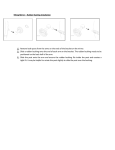
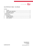
29
Tools...\Check & Adjust
29.1
Overview
Description
Leica instruments are manufactured, assembled and adjusted to the best possible quality.
Quick temperature changes, shock or stress can cause deviations and influence the instrument accuracy.
It is therefore recommended to check and adjust the instrument from time to time. This can
be done in the field by running through specific measurement procedures. The procedures
are guided and have to be followed carefully and precisely as described in the following
chapters. Some other instrument errors and mechanical parts can be adjusted mechanically.
Electronic adjustment
The following instrument errors can be checked & adjusted electronically:
l, t
i
c
a
ATR
Compensator longitudinal and transversal index errors
Vertical index error, related to the standing axis
Hz collimation error, also called line of sight error
Tilting axis error
ATR zero point error for Hz and V - option
Every angle measured in the daily work is corrected automatically if the compensator and
the Hz-corrections are activated in the instrument configuration. Select Main Menu:
Config...\Instrument Settings...\Compensator to check the settings.
The results from check and adjust are displayed as errors but used with the opposite sign as
corrections when applied to measurements.
Mechanical adjustment
Tools...\Check & Adjust
Refer to the Leica TPS1200+ User Manual/TS30/TM30 User Manual for details.
TPS1200+/TS30/TM30
535
Precise measurements
)
)
Tools...\Check & Adjust
To get precise measurements in the daily work, it is important:
• To check and adjust the instrument from time to time.
• To take high precision measurements during the check and adjust procedures.
• To measure targets in two faces. Some of the instrument errors are eliminated by averaging the angles from both faces.
• To follow the four advices below.
During the manufacturing process, the instrument errors are carefully determined and set to
zero. As mentioned above, these errors can change and it is highly recommended to redetermine them in the following situations:
• Before the first use
• Before every high precision survey
• After rough or long transportations
• After long working periods
• After long storage periods
• If the temperature difference between current environment and the temperature at the last
calibration is more than 20°C
Before determining the instrument errors, the instrument has to be levelled up
using the electronic level. SHIFT F12 to access STATUS Level & Laser
Plummet, Refer to "31.7 STATUS: Level & Laser Plummet".
The tribrach, the tripod and the underground should be very stable and secure
from vibrations or other disturbances.
TPS1200+/TS30/TM30
536
)
)
The instrument should be protected from direct sunlight in order to avoid thermal
warming in general and especially on one side of the instrument housing.
It is also recommended to avoid strong heat shimmer and air turbulences.The best
conditions can be found usually early in the morning and with overcast sky.
+20°C
Before starting to work, the instrument has to
become acclimatised to the ambient temperature. Approximately two minutes per °C
temperature difference from storage to
working environment but at least 15 min
should be taken into account.
°C
+20°C
°C
TPS12_171
Tools...\Check & Adjust
> 15 min
TPS1200+/TS30/TM30
537
29.2
Details on Instrument Errors
General
Instrument errors occur, if the standing axis, the tilting axis and the line of sight are not
precisely perpendicular to each other.
Hz collimation error (c)
c
d
b
a
a) Tilting axis
b) Line perpendicular to tilting axis
c) Hz collimation error (c), also called line of sight
error
d) Line of sight
TPS12_026
The Hz collimation error (c) is also called line of sight error. It is caused by the deviation
between the optical line of sight, which means the direction in which the crosshairs points
and the line perpendicular to the tilting axis. This error affects all Hz readings and increases
with steep sightings.
Tools...\Check & Adjust
TPS1200+/TS30/TM30
538
Tilting axis error (a)
r
b
a
d
c
TPS12_027
a) Axis perpendicular to the vertical axis
b) Mechanical vertical axis of the instrument, also
called standing axis
c) Tilting axis error
d) Tilting axis
The tilting axis error (a) is caused by the deviation between the mechanical tilting axis and
the line perpendicular to the vertical axis.
This error affects Hz angles. The affection is 0 in the horizon and increases with steep sights.
To determine this error, it is necessary to point to a target located significantly below or above
the horizontal plane. To avoid influences from the Hz collimation error (c), this has to be
determined prior to the tilting axis error.
Tools...\Check & Adjust
TPS1200+/TS30/TM30
539
Vertical index error (i)
a
b
d
c
a) Mechanical vertical axis of the instrument, also
called standing axis
b) Axis perpendicular to the vertical axis
c) V = 90° reading in a specific face
d) Vertical index error
TPS12_023
A vertical index error (i) exists, if the 0° mark of the vertical circle reading doesn’t coincide
with the mechanical vertical axis of the instrument, also called standing axis.
The V index error (i) is a constant error that affects all vertical angle readings.
Tools...\Check & Adjust
TPS1200+/TS30/TM30
540
Compensator index
errors (l, t)
a b
b
c
a
d
TPS12_022
a) Mechanical vertical axis of the instrument, also
called standing axis
b) Plumb line
c) Longitudinal component (l) of the compensator
index error
d) Transversal component (t) of the compensator
index error
The compensator index errors (l, t) occur, if the vertical axis of the instrument and the plumbline are parallel but the zero points of the compensator and the circular level do not coincide.
The calibration procedure electronically adjusts the zero point of the compensator.
The plane of the dual axis compensator of the TPS1200+/TS30/TM30 is defined by a longitudinal component in direction of the telescope and a transversal component perpendicular
to the telescope.
The longitudinal compensator index error (l) has a similar effect as the vertical index error
and affects all vertical angle readings.
The transversal compensator index error (t) is similar to the tilting axis error. The effect of this
error to the Hz angle readings is 0 at the horizon and increases with steep sightings.
Tools...\Check & Adjust
TPS1200+/TS30/TM30
541
ATR collimation errors
d
a
c
a)
b)
c)
d)
b
TPS12_028
Centre of prism
Crosshairs
V component of ATR collimation error
Hz component of ATR collimation error
The ATR collimation error is the angular divergence between the line of sight, which means
the direction in which the crosshairs points, and the ATR CCD camera axis, which detects
the centre of the prism. Hz and V angles are corrected by the Hz and V components of the
ATR calibration errors to measure exactly to the centre of the prism.
)
Tools...\Check & Adjust
Note, that even after adjustment of the ATR, the crosshairs might not be positioned exactly
on the centre of the prism after an ATR search. This is a normal effect. To speed up the ATR
search, the telescope is not positioned exactly on the centre of the prism. The small rest deviations, the ATR offsets, are measured individually for each measurement and corrected
electronically. This means that the Hz- and V- angles are corrected twice: first by the determined ATR errors for Hz and V and then by the individual small deviations of the current
pointing, the ATR offsets.
TPS1200+/TS30/TM30
542
Summary of errors to be
adjusted electronically
Tools...\Check & Adjust
Instrument error
Effects Hz
Effects V
Elimination
with two face
measurement
Automatically
corrected with
proper adjustment
c - Hz collimation error
9
-
9
9
a - Tilting axis error
9
-
9
9
l - Compensator index error
-
9
9
9
t - Compensator index error
9
-
9
9
i - V-Index error
-
9
9
9
ATR Collimation error
9
9
-
9
TPS1200+/TS30/TM30
543
29.3
Accessing Check & Adjust Menu
Access
Select Main Menu: Tools...\Check & Adjust...
OR
Press a hot key configured to access the screen TOOLS Check & Adjust Menu. Refer
to "2.1 Hot Keys" for information on hot keys.
OR
Press USER. Refer to "2.2 USER Key" for information on the USER key.
TOOLS
Check & Adjust Menu
CONT (F1)
To select the highlighted option and to continue
with the subsequent screen.
CONF (F2)
To access the TOOLS Configuration screen.
Refer to "29.4 Configure Check & Adjust".
Tools...\Check & Adjust
TPS1200+/TS30/TM30
544
Description of the Check & Adjust functions
Function
Description
Refer to
chapter
Combined (l,t,i,c,ATR) To determine the l, t, i, c and ATR instrument errors. 29.5
Tilting Axis (a)
To determine the tilting axis (a) error.
29.6
Compensator (l,t)
To determine the compensator (l, t) errors.
29.7
Current Values
To view the current instrument errors
29.8
End Check & Adjust
To exit the TOOLS Check & Adjust Menu.
Next step
IF the task is to
THEN
determine the instrument errors
select one of the three available check and adjust procedures:
Combined (l, t, i, c, ATR), Tilting Axis (a) or Compensator (l, t).
adjust the circular level
Refer to "29.9 Adjusting the Circular Level of the Instrument and
Tribrach".
inspect the laser
plummet
Refer to "29.11 Inspecting the Laser Plummet of the Instrument".
adjust the tripod
Refer to "29.12 Servicing the Tripod".
to end check and adjust select End Check & Adjust.
Tools...\Check & Adjust
TPS1200+/TS30/TM30
545
29.4
Access step-by-step
Configure Check & Adjust
Step
Description
1.
Refer to "29.3 Accessing Check & Adjust Menu" to access TOOLS Check &
Adjust Menu.
2.
CONF (F2) to access TOOLS Configuration.
TOOLS
Configuration,
Parameters page
CONT (F1)
To accept the settings and to return to the
screen TOOLS Check & Adjust Menu
PAGE (F6)
To change to another page on this screen.
Tools...\Check & Adjust
TPS1200+/TS30/TM30
546
Description of fields
Field
Option
Description
<Adjust
Reminder:>
2 weeks,
1 month,
3 months,
6 months,
12 months or
A reminder message is displayed each time the
instrument is turned on if one or more adjustment
values were determined longer ago than the time
specified with this parameter. This helps to redetermine the instrument errors on a regular basis.
Never
A reminder message to readjust the instrument is
never displayed. This setting is not recommended.
Next step
PAGE (F6) changes to the Logfile page.
TOOLS
Configuration,
Logfile page
Tools...\Check & Adjust
Description of fields
Field
Option
Description
<Write Logfile:>
Yes or No
To generate a logfile when the application program is
exited.
A logfile is a file to which data from an application
program is written to. It is generated using the selected
<Format File:>.
<File Name:>
Choicelist
Available for <Write Logfile: Yes>. The name of the file
to which the data should be written. A logfile is stored in
the \DATA directory of the active memory device. The
data is always appended to the file.
TPS1200+/TS30/TM30
547
Field
Option
Description
Opening the choicelist accesses XX Logfiles where a
name for a new logfile can be created and an existing
logfile can be selected or deleted.
<Format File:>
Choicelist
Available for <Write Logfile: Yes>. A format file defines
which and how data is written to a logfile. Format files
are created using LGO. A format file must first be transferred from the CompactFlash card to the System RAM
before it can be selected. Refer to "24 Tools...\Transfer
Objects..." for information on how to transfer a format
file.
Opening the choicelist accesses XX Format Files
where an existing format file can be selected or deleted.
Next step
PAGE (F6) changes back to the Parameters page.
Tools...\Check & Adjust
TPS1200+/TS30/TM30
548
29.5
Access step-by-step
Description
Combined Adjustment (l, t, i, c and ATR)
Step
1.
Refer to "29.3 Accessing Check & Adjust Menu" to access TOOLS Check &
Adjust Menu.
2.
In TOOLS Check & Adjust Menu highlight Combined (l,t,i,c,ATR).
3.
CONT (F1) to access TOOLS Combined I.
The combined adjustment procedure determines the following instrument errors in one
process:
l, t
i
c
ATR Hz
ATR V
Tools...\Check & Adjust
Description
Compensator longitudinal and transversal index errors
Vertical index error, related to the standing axis
Hz collimation error, also called line of sight error
ATR zero point error for Hz angle - option
ATR zero point error for V angle - option
TPS1200+/TS30/TM30
549
Combined procedure
step-by-step
The following table explains the most common settings. Refer to the stated chapter for more
information on screens.
Step
)
1.
Description
Refer to
chapter
Before determining the instrument errors, the instrument has to be:
• levelled up using the electronic level
• protected from direct sunlight
• acclimatised to the ambient temperature, approximately two
minutes per °C difference compared to the storage place.
• Refer to "29.1 Overview" paragraph "Precise measurements" for
more details.
TOOLS Check & Adjust Menu
Select the option Combined (l,t,i,c,ATR)
2.
TOOLS Combined I
<ATR Adjust: On> Includes the determination of the ATR, Hz and V
adjustment values if an ATR is available.
It is recommended to use a clean Leica circular prism as target,
for example a GPR1. Do not use a 360° prism.
)
<ATR Adjust: Off> ATR Hz and V adjustment value determination is
not included. A prism is not necessarily required to run the procedure.
Tools...\Check & Adjust
TPS1200+/TS30/TM30
550
Step
Description
Refer to
chapter
3.
0m
0
~1
± 9°
Aim the telescope accurately
at a target at a distance of
about 100 m. The target
must be positioned within
± 9°/± 10 gon of the horizontal plane
The procedure can be
started in any telescope face.
The fine pointing has
to be performed manually in
both faces.
)
)
TPS12_024
Tools...\Check & Adjust
TPS1200+/TS30/TM30
551
Step
4.
Description
Refer to
chapter
MEAS (F1) to measure and to continue to the next screen.
Motorised instruments
change automatically to the
other face.
180°
180°
TPS12_025
Non-motorised TPS1200+ instruments guide to the other face using 32
the TOOLS Telescope Positioning screen.
5.
)
6.
Tools...\Check & Adjust
TOOLS Combined II
MEAS (F1) to measure the same target in the other face and to calculate the instrument errors.
If one or more errors are bigger than the predefined limits, the procedure has to be repeated. All measurements of the current run are
rejected and are not averaged with the results from previous runs.
TOOLS Adjustment Accuracy
TPS1200+/TS30/TM30
552
Step
Description
Refer to
chapter
<No. of Meas:> Shows the number of runs executed. One run
consists of a measurement in face I and face II.
)
7.
All other fields display the standard deviations of the determined
adjustment errors. The standard deviations can be calculated from
the second run onwards.
It is recommended to measure at least two runs.
MEAS (F5) if more runs have to be added. Continue with step 2.
OR
CONT (F1) to accept the measurements and to access TOOLS
Adjustment Results. No more runs can be added later.
TOOLS
Adjustment Results
CONT (F1)
To accept and store the new determined instrument errors, where Yes is set in the Use
column. Writes to or appends to an existing
logfile, if the logfile recording has been
enabled. Refer to "29.4 Configure Check &
Adjust".
USE (F4)
To set Yes or No in the Use column for the
highlighted set.
Tools...\Check & Adjust
TPS1200+/TS30/TM30
553
MORE (F5)
To view additional information about the
current used old instrument errors.
REDO (F2)
To reject all results and to repeat the complete
check and adjust procedure. Refer to step 2. of
paragraph "Combined procedure step-bystep".
Description of columns and fields
Column
Option
Description
New [g]
-----
Shows the new determined and averaged instrument
errors. The unit is displayed in [].
Use
Yes
Stores the new adjustment error.
No
Keeps the currently used error active on the instrument and rejects the new one.
-----
Shows the old adjustment errors, which are currently
valid on the instrument. The unit is displayed in [].
Old [g]
Next step
Tools...\Check & Adjust
IF the results are
THEN
to be stored
CONT (F1) overwrites the old adjustment errors with the new ones, if
Yes is set in the Use column.
TPS1200+/TS30/TM30
554
Tools...\Check & Adjust
IF the results are
THEN
to be determined
again
REDO (F2) rejects all new determined adjustment values and repeats
the whole procedure. Refer to step 2. of paragraph "Combined procedure step-by-step".
TPS1200+/TS30/TM30
555
29.6
Access step-by-step
Description
Tilting Axis Adjustment (a)
Step
1.
Refer to "29.3 Accessing Check & Adjust Menu" to access TOOLS Check &
Adjust Menu.
2.
In TOOLS Check & Adjust Menu highlight Tilting Axis (a).
3.
CONT (F1) to access TOOLS Tilting-Axis Adjustment I.
This procedure determines the following instrument error:
a
Tilting axis adjustment
step-by-step
Description
Tilting axis error
The following table explains the most common settings. Refer to the stated chapter for more
information on screens.
Step
Description
)
Before determining the tilting axis error, the instrument has to be:
1.
•
levelled up using the electronic level
•
protected from direct sunlight
•
acclimatised to the ambient temperature, approximately two
minutes per °C difference compared to the storage place.
•
The Hz collimation error has to be determined before.
Refer to
chapter
29.1, 29.5
TOOLS Check & Adjust Menu
Select the option: Tilting Axis (a)
Tools...\Check & Adjust
TPS1200+/TS30/TM30
556
Step
2.
Description
Refer to
chapter
TOOLS Tilting-Axis Adjustment I
+ 27°
°
90
V=
- 27°
Aim the telescope accurately
at a target at a distance of
about 100 m. For distances
less than 100 m make sure to
precisely point to the target.
The target must be positioned
within at least 27°/30 gon
above or beneath the horizontal plane.
The procedure can be
started in any telescope face.
The fine pointing has to
be performed manually in both
faces.
)
)
TPS12_024a
Tools...\Check & Adjust
TPS1200+/TS30/TM30
557
Step
3.
Description
Refer to
chapter
MEAS (F1) to measure and to continue to the next screen.
Motorised instruments
change automatically to the
other face.
180°
180°
TPS12_025
Non-motorised TPS1200+ instruments guide to the other face using 32
the TOOLS Telescope Positioning screen.
4.
)
5.
Tools...\Check & Adjust
TOOLS Tilting Axis Adjustment II
MEAS (F1) to measure the same target in the other face and to calculate the tilting axis error.
If the error is bigger than the predefined limit, the procedure has to be
repeated. The measurements of the current run are then rejected and
not averaged with the results from previous runs.
TOOLS T-Axis Adjustment Accuracy
TPS1200+/TS30/TM30
558
Step
Description
Refer to
chapter
<No. of Meas:> Shows the number of runs executed. One run
consists of a measurement in face I and face II.
)
6.
<ı a T-axis:> shows the standard deviation of the determined tilting
axis error. The standard deviation can be calculated from the second
run onwards.
It is recommended to measure at least 2 runs.
MEAS (F5) if more runs have to be added. Continue with step 2.
OR
CONT (F1) to accept the measurements and to access TOOLS TAxis Adjustment Result. No more runs can be added later.
TOOLS
T-Axis Adjustment
Result
Tools...\Check & Adjust
CONT (F1)
To accept and record the new determined
tilting axis error. Writes to or appends to an
existing logfile, if the logfile recording has been
enabled. Refer to "29.4 Configure Check &
Adjust".
REDO (F2)
To reject the result and to repeat the complete
check and adjust procedure. Refer to step 2. of
paragraph "Tilting axis adjustment step-bystep".
TPS1200+/TS30/TM30
559
Description of columns and fields
Column
Option
Description
New [g]
-----
Shows the new determined and averaged tilting axis
error. The unit is displayed in [].
Old [g]
-----
Shows the old instrument error, which is currently
valid on the instrument. The unit is displayed in [].
Next step
Tools...\Check & Adjust
IF the result is
THEN
to be stored
CONT (F1) overwrites the old tilting axis error with the new one.
to be determined
again
REDO (F2) rejects the new determined tilting axis error and repeats
the whole procedure. Refer to step 2. of paragraph "Tilting axis
adjustment step-by-step".
TPS1200+/TS30/TM30
560
29.7
Access step-by-step
Description
Compensator Adjustment (l, t)
Step
1.
Refer to "29.3 Accessing Check & Adjust Menu" to access TOOLS Check &
Adjust Menu.
2.
In TOOLS Check & Adjust Menu highlight Compensator (l,t).
3.
CONT (F1) to access TOOLS Compensator Adjustment.
The compensator adjustment procedure determines the following instrument errors:
l
t
Compensator index
adjustment step-bystep
Compensator longitudinal index error
Compensator transversal index error
The following table explains the most common settings. Refer to the stated chapter for more
information on screens.
Step
Description
)
Before determining the compensator index errors, the instrument has
to be:
1.
Tools...\Check & Adjust
Description
•
levelled up using the electronic level
•
protected from direct sunlight
•
acclimatised to the ambient temperature, approximately two
minutes per °C difference compared to the storage place.
Refer to
chapter
29.1
TOOLS Check & Adjust Menu
TPS1200+/TS30/TM30
561
Step
Description
Refer to
chapter
Select the option: Compensator (l, t)
2.
TOOLS Compensator Adjustment
MEAS (F1) to measure the first face. No target has to be aimed at.
Motorised instruments change to the other face and
180°
release a measurement automatically.
Non-motorised TPS1200+ instruments guide to the
other face using the TOOLS Telescope Positioning
screen.
MEAS (F1) to release the measurement in the other
face.
)
3.
TPS12_025a
If one or more errors are bigger than the predefined limits, the procedure has to be repeated. All measurements of the current run are
rejected and are not averaged with the results from previous runs.
TOOLS Comp Adjustment Accuracy
<No. of Meas:> Shows the number of runs executed. One run
consists of a measurement in face I and face II.
)
Tools...\Check & Adjust
<ı l Comp:> and <ı t Comp:> show the standard deviations of the
determined adjustment errors. The standard deviations can be calculated from the second run onwards.
It is recommended to measure at least two runs.
TPS1200+/TS30/TM30
562
Step
4.
Description
Refer to
chapter
MEAS (F5) if more runs have to be added. Continue with step 2.
OR
CONT (F1) to accept the measurements and to access TOOLS
Comp Adjustment Results. No more runs can be added later.
TOOLS
Comp Adjustment
Results
CONT (F1)
To accept and record the new determined
instrument errors. Writes to or appends to an
existing logfile, if the logfile recording has been
enabled. Refer to "29.4 Configure Check &
Adjust".
REDO (F2)
To reject all results and to repeat the complete
check and adjust procedure. Refer to step 2. of
paragraph "Compensator index adjustment
step-by-step".
Description of columns and fields
Tools...\Check & Adjust
Column
Option
Description
New [g]
-----
Shows the new determined and averaged instrument
errors. The unit is displayed in [].
TPS1200+/TS30/TM30
563
Column
Option
Description
Old [g]
-----
Shows the old instrument errors, which are currently
valid on the instrument. The unit is displayed in [].
Next step
Tools...\Check & Adjust
IF the results are
THEN
to be stored
CONT (F1) overwrites the old instrument errors with the new ones.
to be determined
again
REDO (F2) rejects the new determined instrument errors and repeats
the whole procedure. Refer to step 2. of paragraph "Compensator
index adjustment step-by-step".
TPS1200+/TS30/TM30
564
29.8
Access
Current Instrument Errors
Step
Description
1.
Refer to "29.3 Accessing Check & Adjust Menu" to access TOOLS Check &
Adjust Menu.
2.
In TOOLS Check & Adjust Menu highlight Current Values.
3.
CONT (F1) to access TOOLS Current Values.
TOOLS
Current Values
CONT (F1)
To return to the TOOLS Check & Adjust
Menu screen. Refer to "29.3 Accessing Check
& Adjust Menu".
MORE (F5)
To display information about the date of the
determination, the standard deviation of the
errors and the temperature during the determination.
Next step
CONT (F1) returns to TOOLS Check & Adjust Menu screen. Refer to "29.3 Accessing
Check & Adjust Menu".
Tools...\Check & Adjust
TPS1200+/TS30/TM30
565