1
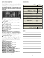
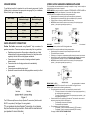
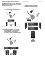
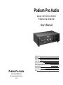
Podium Pro Audio Model VX1000 & VX2000 Professional Amplifier User’s Manual Podium Pro Audio Audio at its highest level http://www.podiumproaudio.com © 2010 INTRODUCTION FEATURES PRECAUTIONS INSTALLATION FRONT PANEL CONTROLS INPUT / OUTPUT CONNECTIONS STEREO, MONO AND BRIDGE MODES EXPLAINED SELECT THE BEST MODE FOR YOUR APPLICATION SPEAKER WIRING USING SPEAKON® CONNECTORS SPECIFICATIONS NOTES 2 2 2 2 3 4 5 6-7 8 8 9 9 INTRODUCTION The Podium Pro Audio VX1000 & VX2000 are high performance two channel power amplifiers intended for professional sound reinforcement and public address applications. Sophisticated protection circuitry is employed to ensure that your audience and speakers are fully protected from all typical fault conditions. Used in accordance with the information provided in this manual, this product will give years of trouble free use. FEATURES • • • • • • DC protection disconnects speakers if a DC fault is detected Over-temperature protection shuts down amplifier if overheated Output short-circuit protection Cooling fan varies speed in response to operating conditions “SPEAKON” speaker connectors Rugged steel construction PRECAUTIONS • Do not use where the amplifier may get wet. • Never place the amplifier near any heat source. • Do not obstruct the air vents. Doing so may cause the amplifier to overheat. • The third, round pin on the AC cord is an essential safety feature. Never defeat the safety ground on the AC cord. • Be certain all equipment is OFF before making or breaking connections. • Refer all service needs to qualified personnel. There are no user serviceable components inside. INSTALLATION The VX amplifier is designed for either shelf or equipment rack installations. If you plan to place the amplifier into an equipment rack with other pieces of equipment, you will need to remove the four rubber feet. They are easily removed with a #2 Phillips screwdriver. If the equipment rack contains numerous amplifiers, you must ensure adequate ventilation or overheating may result. 11 2 FRONT PANEL CONTROLS ① AC POWER SWITCH ② POWER LED This blue LED lights whenever the amplifier is on. ③ FAN LED This blue LED lights whenever the cooling fan is on. ④ MODE SELECT This three position switch selects one of the three available operating modes. A summary is provided here. For a detailed explanation of all MODES, see “STEREO, MONO AND BRIDGE MODES EXPLAINED” on page 6. • • • 10 STEREO In this position the amplifier operates as a normal two channel amplifier. Channel A = LEFT, channel B = RIGHT. MONO In this position the signal applied to the channel A input will be present on both A and B outputs. Each channel’s volume control (VOL) will continue to operate independently. BRIDGE In “BRIDGE” mode, the amplifier is configured to operate as a single high power channel. Connect your source to the channel A input. Connect your speaker to the center Speakon® jack or use the five-way binding posts. The RED channel A binding post = speaker (+). The RED channel B binding post = speaker (-). Use the CHANNEL A VOL control to adjust amplifier volume. ⑤ CHANNEL A VOL [ LEFT CHANNEL ] This rotary control adjusts the volume of channel A only. The control is detented, allowing a precise volume match between channel A and B. ⑥ CHANNEL A [ LEFT ] SIGNAL LED This green LED lights whenever signal is present on channel A. ⑦ CHANNEL A [LEFT ] CLIP LED This yellow LED lights whenever channel A is driven above its maximum output voltage. ⑧ CHANNEL A PROTECT LED This red LED lights whenever channel A encounters an excessive load, i.e. shorted speaker cable. When this occurs you must correct the fault. ⑨ CHANNEL B VOL [ Right Channel ] This rotary control adjusts the volume of channel B only. The control is detented, allowing a precise volume match between channel A and B. ⑩ CHANNEL B SIGNAL LED This green LED lights whenever signal is present on channel B. ⑪ CHANNEL B CLIP LED This yellow LED lights whenever channel B is driven above its maximum output voltage. ⑫ CHANNEL B PROTECT LED This red LED lights whenever channel B encounters an excessive load, i.e. shorted speaker cable. When this occurs you must correct the fault. 3 INPUT / OUTPUT CONNECTIONS SPECIFICATIONS It is essential that all input and output connections are wired correctly and are of high quality. We recommend using only pre-fabricated cables which adhere to the wiring conventions detailed here. VX1000 Class NOTE: Although each input channel has three connector types you must only use one at a time. Use an audio mixing console if you want to combine multiple sources. ① LINE A XLR INPUT Balanced: PIN 1 = ground, PIN 2 = (+), PIN 3 = (-). Unbalanced: PIN 1 = ground, PIN 2 = (+), PIN 3 = ground. ② LINE B XLR INPUT Balanced: PIN 1 = ground, PIN 2 = (+), PIN 3 = (-). Unbalanced: PIN 1 = ground, PIN 2 = (+), PIN 3 = ground. ③ LINE A ¼” PHONE JACK INPUT Balanced: TIP = (+), RING = (-), SLEEVE = ground. Unbalanced: TIP = (+), RING = ground, SLEEVE = ground. ④ LINE B ¼” PHONE JACK INPUT Balanced: TIP = (+), RING = (-), SLEEVE = ground. Unbalanced: TIP = (+), RING = ground, SLEEVE = ground. ⑤ STEREO “CD” INPUT Unbalanced phono (RCA) jacks. WHITE = LEFT IN = CHANNEL A OUT, RED = RIGHT IN = CHANNEL B OUT. The second pair of phono jacks are provided as a convenient pass through of the input signal. NOTE: this input can be used with any unbalanced analog line level audio source. This includes tape players, iPods, MP3 players and computers. ⑥ INPUT GROUND “FLOAT” SWITCH Normally, amplifier circuit “ground” is connected to chassis ground. It is recommended that you leave this switch in the “GND” position at all times. In some rare cases it may be beneficial to isolate, or “FLOAT” the amplifier circuit grounds from the chassis ground. To do this, set this switch to the “FLOAT” position. ® ⑦ CHANNEL A SPEAKON OUTPUT AB Peak power, 4Ω 2x500W 2x1000W Peak power, 8Ω 2x250W 2x500W Peak power, BRIDGED, 4Ω 1000W 2000W Balanced input sensitivity 700mV Unbalanced input sensitivity 350mV Signal to noise ratio ≥96dB Frequency response 15Hz – 25kHz Distortion (THD+N) ≤0.5% Balanced input impedance 20kΩ Unbalanced input impedance 10kΩ AC power requirement 115V/60Hz or 230V/50Hz AC Fuse T10A H250V NOTES ® See “USING SPEAKON CONNECTORS” on page 4 for details. ⑧ CHANNEL B SPEAKON OUTPUT ® ® See “USING SPEAKON CONNECTORS” on page 4 for details. ⑨ BRIDGE MODE SPEAKON OUTPUT ® ® See “USING SPEAKON CONNECTORS” on page 4 for details. ⑩ CHANNEL A “5-WAY” BINDING POST OUTPUT RED binding post = speaker (+), BLACK binding post = speaker (-). See “SPEAKER WIRING” on page 4 for detailed information. ⑪ CHANNEL B “5-WAY” BINDING POST OUTPUT RED binding post = speaker (+), BLACK binding post = speaker (-). See “SPEAKER WIRING” on page 4 for detailed information. 4 VX2000 9 T5A H250V SPEAKER WIRING STEREO, MONO AND BRIDGE MODES EXPLAINED To get the best results it is important to use the correct gauge wire. Use the following table to determine the appropriate wire gauge for your installation. When in doubt, go to a larger gauge. Wire Gauge 8Ω Speaker Maximum Length 4Ω Speaker Maximum Length 18 10 feet 5 feet 16 20 feet 10 feet 14 35 feet 18 feet 12 60 feet 30 feet 10 100 feet 50 feet USING SPEAKON® CONNECTORS ® Podium Pro Audio recommends using Speakon style connectors for speaker connections. There are numerous reasons why this is a good idea. • • • • • Regulatory requirements in Europe have outlawed the use of dual banana plugs for high powered amplifiers and it is likely that similar regulatory controls will eventually appear worldwide. Connectors cannot be reversed, eliminating accidental speaker phase reversal. Connectors lock onto the plug and cannot be accidentally disconnected. Connectors are completely shock proof. Speakon® connectors meets all safety regulations currently in effect. To fully appreciate the potential benefits of operating the amplifier in “bridge” mode it is helpful to briefly examine all three modes of operation. STEREO MODE: Normally, the amplifier is operated in STEREO MODE. In STEREO MODE the two channels of amplification are independent of one another. See Figure A below. In STEREO MODE, the amplifier exhibits the following characteristics. . . • Signals applied to the channel A (left) input are amplified only by channel A. • Signals applied to the channel B (right) input are amplified only by channel B. • Channel A has no influence on channel B and vice versa. • NOTE: Both channel A and B outputs are non-inverting: If the input signal goes positive (+), the output signal also goes positive (+). MONO MODE: When the amplifier is operated in MONO MODE, signals applied to the channel A input are amplified by channel A and B. See Figure B above. In MONO MODE, the amplifier exhibits the following characteristics. . . • Signals applied to the channel A input are amplified by channel A and B. • The channel B input is disabled. • Effectively you now have two independent amplifiers sharing the same input channel. • Although both A and B output channels will be identical, each channels’ volume level can be independently adjusted. See page 6 “FRONT PANEL CONTROLS”. • NOTE: Both channel A and B outputs are non-inverting: If the input signal goes positive (+), the output signal also goes positive (+). BRIDGE MODE: In BRIDGE MODE, channel A and B amplify the signal applied to the channel A input. Unlike MONO MODE, the channel B output is inverted. See Figure C below. Figure 1 ® The VX Series amplifiers use four pin Speakon connectors (Neutrik model NL4FC or equivalent). See Figure 1 for wiring details. If your speakers also have Speakon® connectors, do not assume they use the same wiring convention. Check with the manufacturer of your speakers for more information. 8 BRIDGE MODE operation has the following characteristics. . . • The signal applied to the channel A input is amplified by channel A and B. o The output of channel A is non-inverted: If the input signal goes positive (+), the output signal also goes positive (+). o The output of channel B is inverted: If the input signal goes positive (+), the output signal goes negative (-). • Channel A and B are now operating as one channel. The channel A volume control adjusts the output level of both A and B together. o The channel B volume control is disabled. o The channel B input is disabled. • The loudspeaker is not connected to ground. o The speaker (+) lead is connected to channel A (RED connector). o The speaker (-) lead is connected to channel B (RED connector). See page 3, “INPUT / OUTPUT CONNECTIONS” 5 SELECT THE BEST MODE FOR YOUR APPLICATION STEREO MODE: For most applications, STEREO MODE is the best choice. This gives you two independent, high power channels of amplification. STEREO MODE is your best choice for the following conditions. You have a stereo source and. . . • • BRIDGE MODE: When the highest possible power output is desired, BRIDGE MODE is the best choice. This is an excellent way to power a large subwoofer. You have a single channel source or two amplifiers for a stereo source and. . . • • Will be connecting one speaker, minimum impedance: 4Ω. Will be connecting one or two 8Ω speakers in parallel. Will be connecting one 4Ω or 8Ω speaker to each output channel. Will be connecting two 8Ω speakers in parallel to each output channel. MONO MODE: There are a number of circumstances where MONO MODE is the best option. You have a single channel source or two amplifiers for a stereo source and. . . • • A very large venue where speaker wire lengths are excessive. MONO MODE allows amplifier placement much closer to the speakers. Sound reinforcement: Driving a cluster of several speakers. MONO MODE allows a single amplifier to drive up to four 8Ω speakers or two 4Ω speakers. 6 7