1
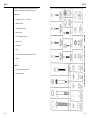
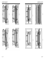
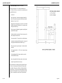
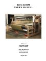
RUG LOOM
USER'S MANUAL
AVL Looms
2360 Park Avenue
Chico, CA 95928
Sales: 800 626-9615
[email protected]
www.avlusa.com
August 2010
TABLE OF CONTENTS
Preface
Before You Begin
1
1
TOOLS
•
•
•
Necessary Tools
Helpful Tools
Figure 1 - Hardware Identification Chart
2
2
3
HARDWARE
•
Hardware Hints
4
ASSEMBLY
SEQUENCE
•
•
•
•
•
•
•
•
•
•
•
•
•
•
•
•
•
•
•
•
•
•
•
•
•
•
•
•
•
•
•
•
•
•
•
•
•
•
Side Frame Assembly
Figure 2 - Right Side Frame Assembly
Figure 3 - Left Side Frame Assembly
Lower Back
Figure 4 - Assembling Lower Left Back Corner
Spring Lever Assembly
Harness Pulley Support Assembly
Square the Frame
Lower Front
Upper Back
Figure 5
Level the Frame
Dobby Assembly
Beater Assembly
Figure 6
Air System
Figure 7 - Dobby/Side View
Figure 8
Figure 9 - Dobby/Front View
Figure 10 - Basic Rug Loom Air System
Figure 11
Harnesses Assemblies
Figure 12
Cloth Storage Beam Assembly
Figure 13 - Cloth Storage Beam
Figure 14 - Installing Cloth Beam
Cloth Beam Assembly
Figure 15
Separation Rollers
Figure 16 - Installing Separation Roller
Worm Drive
Figure 17 - Cloth Storage Crankshaft Assembly
Warp Beams
Figure 18 - Cloth Beam Handle
Brake Cable Assembly
Figure 19
Brake Drag Strap
Figure 20 - Brake Drag Strap
AS-6
AS-7
AS-8
AS-9
AS-10
AS-10
AS-10
AS-11
AS-11
AS-12
AS-12
AS-13
AS-13
AS-13
AS-14
AS-15
AS-15
AS-16
AS-17
AS-19
AS-20
AS-20
AS-22
AS-23
AS-23
AS-23
AS-24
AS-25
AS-26
AS-26
AS-27
AS-27
AS-28
AS-28
AS-29
AS-29
AS-30
AS-30
Page TOC-1
TABLE OF CONTENTS
WARPING THE
SECTIONAL BEAM
TWO OR MORE
WARPS
Page TOC-2
TABLE OF CONTENTS
•
•
•
•
Figure 21 - Brake Cable Adjuster
Figure 22
Apron
Connect the Air System
•
Compressor
•
Set Main Air Pressure
•
System Test
•
Add Oil
AS-31
AS-32
AS-33
AS-33
AS-33
AS-34
AS-34
AS-34
•
•
•
•
•
•
•
•
•
•
•
•
•
•
•
•
•
•
•
•
•
•
•
Sectional Beam Calculation
Extension Cords
Feeding the Spool Rack
Adjusting the Tension Device
Setting a Tracking System
Tension Box
Tension Box Heddle Installation Instructions
Threading the Tension Box
Figure 7W - Tension Box
Winding the Warp
Figure 8W - Winding on the Warp - Half Yard
Sectional Beam in Lower Position
Figure 9W - Winding on the Warp - One Yard
Sectional Beam in Upper Position
Adjusting the Size of the Section
Figure 10W
Figure 11W
Counting Turns or Yardage
Figure 12W - Attaching Yardage Counter to
Tension Box
Creating the Cross
Sticks in the Treading Cross
Routing the Warp
Figure 13W - Routing of Warp with Sectional Beam
Readjusting the Tension
Combining Sectional and Plain Warping
W-1
W-3
W-3
W-4
W-4
W-4
W-4
W-5
W-6
W-7
•
•
•
•
•
•
When do you need to tension your warps separately?
Setting Two Beams
Figure 14W
Figure 15W
Figure 16W
More than Two Warps, Separate Tensioning
T-1
T-1
T-2
T-2
T-3
T-4
W-7
W-8
W-8
W-9
W-9
W-10
W-10
W-11
W-11
W-12
W-12
W-12
W-13
ADDENDA
Special Instructions for the Automatic Advance and Pressure Rollers
•
Pressure Rollers
A-1
•
Pressure Roller Photo
A-1
•
Control Box
A-2
•
Control Box Photo 1
A-2
•
Control Box Photo 2
A-2
•
Automatic Advance
A-3
•
Automatic Advance Photo 1
A-3
•
Automatic Advance Photo 2
A-3
•
Direction of the Cloth Diagram
A-4
AIR SHUTLE
INSTALLATION
AND
ADJUSTMENTS
Installation Figure 1
To Adjust the Beater Height
Figure 2
Figure 3 (side view illustration of beater with warp threads)
To Install the Air Shuttle Assembly
Figure 4A - Left-Side Air Shuttle Box
Figure 4B - Right-Side Air Shuttle Box
Figure 5 - Air Shuttle Control Box with Front Cover On
Figure 6A
Figure 6B
Figure 7A
Figure 7G Figure 8A
Figure 8B
Figure 8C
Figure 9A
Figure 9B
Figure 9C
Figure 9D A1-1
A1-1
A1-1
A1-1
A1-2
A1-3
A1-3
A1-3
A1-3
A1-4
A1-4
A1-5
A1-5
A1-6
A1-6
A1-6
A1-7
A1-7
A1-8
A1-8
Page TOC-3
PREFACE
We hope this manual will do three things for you:
1.)
Guide you, step by step, through the assembly of your loom — so
you’ll be immediately satisfied with its function.
2.)
Help you learn about its various systems and components — so
you’ll be an even more capable weaver.
3.)
Inform you about the care and maintenance of your loom — so
you’ll enjoy a lifetime of dependable service.
BEFORE YOU BEGIN
As we've already said, it’s important that you read this manual and follow
its instructions from beginning to end. A quick read through before you
actually pick up a tool will give you a good overview of the whole assembly process.
The Table of Contents will direct you to each of the major sections. You’ll note that at various places in the text, we’ve inserted a [ ]. This
is a reward box. Just add a checkmark as you complete each segment of
work. You’ll feel great and it’ll help you stay organized.
We know that sometimes you've just got to have a picture, so we've included graphic support where it seems necessary. You may wish to photocopy some of these illustrations and bring them forward with you as you
work through the manual. This will save you a good deal of flipping backand-forth in search of that oh-so-helpful diagram. You'll probably find, for
example, that you need to refer constantly to the Hardware Identification
Chart (Figure 1) and Loom Illustrations (Figures 2 through 4).
One last bit of advice:
Even the narrower rug looms will require the efforts of two people
for many of the assembly operations. Several of the components
can be quite heavy, especially in longer lengths. PLEASE TAKE
PRECAUTIONS TO PROTECT YOUR BACK, YOUR FINGERS, AND FEET WHEN HANDLING THESE PARTS!
Now, read through the manual quickly, then we'll bolt the whole shebang
together.
Page 1
TOOLS
TOOLS
You’ll need a few basic hand tools to assembly your loom. We recommend a couple of others that we think will make your job easier.
[ ]
ratchet and sockets: 7/16”, 1/2”, and 9/16”
[ ]
standard screwdriver
[ ]
medium phillips screwdriver
[ ]
hammer or mallet
[ ]
8” or 10” adjustable end wrench
[ ]
carpenter’s level
[ ]
framing square
[ ]
pliers
[ ]
three wooden blocks or books (approximately 2” thick)
[ ]
step stool
Helpful Tools:
Page 2
[ ]
power screwdriver with assorted bits
[ ]
extra ratchet and sockets
HARDWARE IDENTIFICATION CHART - FIGURE 1
Necessary Tools:
Page 3
HARDWARE
If you don't work with hardware, you may find some of the terms a little
mystifying. Not to worry, we've provided that easy-to-use identification
chart (Figure 1) to help you keep things straight.
Hardware Hints:
Page 4
A.)
If a bolt is a little tight going into a hole, give it a light, friendly tap
with a hammer.
B.)
To start the threads on a nut in a “nut access hole” (Figure 4), you
may need to hold the nut in place with the end of a screwdriver or
a finger tip.
C.)
Always have the large "nut access hole" facing toward the inside of
the loom unless otherwise specified.
D.)
Square nuts always go in "nut access holes" and do not take a
washer.
E.)
But, always put a washer under the head of a hex bolt. Any nut
that is NOT in an access hole also requires a washer. This will
prevent damage to the wood.
F.)
If you have trouble turning a screw into the wood on your loom,
try dressing the threads with a little bar soap.
ASSEMBLY SEQUENCE
Your first task will be to construct the SIDE FRAMES, left and right, to
which you will add the various other loom parts. As you work through the
assembly sequence, you will add components in the following order:
[ ]
lower back
[ ]
upper back
[ ]
spring lever support assembly
[ ]
harness pulley support assembly
[ ]
cloth beam
[ ]
square and level
[ ]
cloth storage beam
[ ]
worm drive assembly
[ ]
beater assembly
[ ]
dobby head
[ ]
harness cables
[ ]
harness frames
[ ]
harness springs
[ ]
air system
[ ]
separation roller
[ ]
warp beam
The following illustrations (OV-A through OV-P) are a pictorial overview
of the sequence of steps necessary to put you loom together. Please do not
use these pictures as a manual. They are for reference purposes only.
Page AS-1
ASSEMBLY SEQUENCE
Page AS-2
ASSEMBLY SEQUENCE
Page AS-3
ASSEMBLY SEQUENCE
Page AS-4
ASSEMBLY SEQUENCE
Page AS-5
ASSEMBLY SEQUENCE
[ ]
ASSEMBLY SEQUENCE
Side Frame Assembly (tool needed: 9/16” ratchet)
You’ll need an area roughly 10’ x 10’ in which to assemble the side
frames. If the floor is concrete, you may want to lay a tarp down to protect
the lacquer finish on the parts.
1.)
Locate Box #1.
2.)
Remove the contents. Note that each component is identified by
number. These numbers correspond to the Side Frame Assembly
diagrams (see Figures 2 and 3).
3.)
Arrange the parts at the periphery of your work area. You will find
it helpful to separate parts, left and right. Also, orient them so that
the large access holes face up.
4.)
Check the contents of the hardware bag against its packing list and
group similar bolts together.
5.)
Each bolt should have been fitted at AVL with a lock washer, a flat
washer, and square nut, in that order.
6.)
Fit your ratchet with a 9/16” socket and leave it with the hardware.
7.)
It’s puzzle time. Beginning with the longest part, 1L, arrange each
of the eight left side frame members as shown in Figure 3.
8.)
Closely compare Figure 3 against each part. Verify that the holes
are lined up.
9.)
Use the appropriate bolts, “A” or “B”, to loosely connect each part
to its neighbors.
10.)
Go back and tighten the bolts (but not so tightly as to crack the
wood beneath the flat washers).
11.)
Remove the completed left side frame to make room for the right.
12.)
Complete the right side frame in the same way.
In the next assembly phase, you’ll hang various cross members between
the side frames. As you progress, the loom frame will become sturdier
and free-standing. Be sure to move the frame to its final position before
it becomes too heavy. A 12’ Rug Loom can weigh as much as a half-ton. Moving the steel beams into place is heavy work, especially for the wider
looms, and we recommend that you have plenty of help at hand at that
point.
Page AS-6
Page AS-7
ASSEMBLY SEQUENCE
Page AS-8
ASSEMBLY SEQUENCE
[ ]
Lower Back
1.)
Find Box #2 and remove and organize its contents. Note that the
cross members have part names instead of numbers.
2.)
Locate the cross member hardware pack. Sort and verify its contents.
3.)
Move the left side frame into position and lay it on the floor with
the access holes facing up. The short, round-topped, vertical member is at the front of the loom.
4.)
Bring the Lower Back to the loom and place it on the floor with the
access holes facing what will be the front of the loom (see Figure
4).
5.)
Use two 3/8” x 4” hex bolt assemblies (bolt/lock washer/flat
washer/square nut) to secure the left end of the Lower Back to the
rear of the left side frame. Snug the bolts down, but do not tighten.
6.)
Repeat for the right side frame. The frame will now stand un-supported (see Figure 5).
Page AS-9
ASSEMBLY SEQUENCE
[ ]
Spring Lever Assembly
[ ]
1.)
Because each Rug Loom is unique, depending on width and options, the Spring Lever Assembly may be packed in a different box. However, the contents of each box are listed on the outside. Locate the Spring Lever Assembly.
In order for the loom to function well, it must be reasonably square and
level. We’ll check for squareness first. You may do this with either a carpenter’s square or a 25’ tape measure.
2.)
Locate the appropriate mounting holes in the side frames and preposition four 4” hex bolt assemblies.
3.)
Bring the Spring Lever Assembly into position. Note: it is correctly oriented if the chains hanging from the levers face the side
frames. If they are to the inside of the loom. There should be a
label affixed to the assembly that indicates the Top/Front.
Square the Frame (tool needed: 25’ tape or carpenter’s square)
1.)
Using a Carpenter’s Square:
•
Check the loom frame at the lower rear corners. Bear
against opposing corners to adjust the frame until it comes
into square.
•
Now, go back and firmly tighten all the cross member bolts
that you previously left only snug.
4.)
Left the assembly into position and slide the bolts home.
2.)
Using a Tape Measure:
5.)
Add the nuts and snug the bolts.
•
[ ]
Harness Pulley Support Assembly
You will use the tape to check the loom’s diagonal measurements. First measure from the inside bottom of the
Left Front Vertical, to the outside front of the right Rear
Vertical. Record your measurement.
1.)
Find the Harness Pulley Support Assembly. It is easily identified
by its three sets of black plastic pulleys.
•
2.)
Bring it to the loom and orient it so that the metal identification
plate faces front. One set of pulleys will be offset to the far right
side of the loom.
Do the same from the Right Front Vertical to the Left Front
Vertical. Record and compare the two measurements. When they are equal, the frame will be square.
•
From opposing corners, bear against the frame as needed to
bring the frame to square.
3.)
This assembly bolts into the loom from the top.
•
4.)
Select two 8” hex bolt assemblies and two 10-1/4” or 12-1/4” stud
assemblies from your hardware assortment. The studs will have a
nylock nut cemented at one end.
When you have put the frame square (within 1/8”), go back
and tighten all the connecting bolts.
[ ]
Lower Front (tool needed: 3 blocks or books)
5.)
You’ll now need to hoist the assembly into position atop the left
and right Top Horizontals. Be very careful of your back; get
extra help if you feel you need it.
1.)
Bring the Lower Front into position between the free-standing side
frames. In this case, orient it so that the access holes face the floor
(see Figure 5).
6.)
Raise the assembly into place and orient it over the appropriate
mounting holes in the Top Horizontals. The ID plate should face
forward.
2.)
Select four more 3/8” x 4” bolt assemblies and pre-position the
bolts in the attachment holes, from the outside of each side frame.
3.)
Place blocks under each Front Vertical, left and right. This will
raise the front of the loom enough for you to install nuts on the bolt
ends where they emerge in the blind access holes.
7.)
Page AS-10
ASSEMBLY SEQUENCE
Bolt it into place. The long studs insert at the rear holes, the 8” hex
bolts in the front.
Page AS-11
ASSEMBLY SEQUENCE
4.)
5.)
Page AS-12
ASSEMBLY SEQUENCE
Place an additional block under the right end of the Lower Front
(see Figure 5).
Lift the left end of the Lower Front until its bolt holes are opposite
those in the side frame. Push the bolts into position and add the
square nuts (it’s tight on the fingers, but this will be the only time
you’ll be so cramped). Snug, but don’t tighten.
[ ]
Level the Frame (tool needed: carpenter’s level)
1.)
Use the level to check the frame across the center of the Front Harness Pulley Support.
2.)
If the bubble is more than slightly beyond the plumb lines, you
may need to shim one or more of the verticals. Failure to level
the loom now may affect the beater operation level. However, the
frame needs to be only reasonably level, not precisely level. You
needn’t be overly concerned unless your floor is seriously cattywompus.
6.)
Repeat at the right end.
7.)
Remove the blocks. You won’t need them again.
[ ]
Upper Back (you’re quickly becoming a world class loom builder)
[ ]
Dobby Assembly
1.)
Again, pre-position connecting bolt assemblies in the appropriate
holes at the upper rear of each side frame.
1.)
The Dobby Head is shipped in its own box. Please locate it now.
2.)
Unpack the head and set aside the other box constituents (dobby
bars, pegs, etc.). Bring the head to the right side of the loom. The
cable array is at the top of the unit.
3.)
The three attachment bolts are already in place in the head. Remove the hex nuts and washers.
4.)
Identify the mounting holes in the Right Side Frame, align the
bolts, and push the head into place (see Figure 5).
5.)
Add the nuts/washers and firmly tighten the head to the frame.
[ ]
Beater Assembly
1.)
The Beater Assembly is quite heavy and you’ll need help to install
it! Note that the mounting brackets are already in place on the side
frames.
2.)
Bring the Beater Assembly to the front of the loom.
3.)
Untape the hardware bag and remove the four short hex bolts with
washers. Locate as well the four wooden blocks we provided. Place two bolts and two blocks on the floor to the outside of each
side frame. You will use these very soon.
4.)
Next, lift the Beater Assembly into position and bolt it into the
mounting brackets, using the four hex bolts you’ve pre-positioned
at each side of the loom. Leave the end bolts loose for the moment
— you still need to adjust the height of the beater.
2.)
Bring the Upper Back to the loom and push the bolts into place.
3.)
Add square nuts and snug.
Page AS-13
ASSEMBLY SEQUENCE
5.)
6.)
ASSEMBLY SEQUENCE
At each side of the loom, insert two blocks under the slide rods,
near the front and rear brackets. These blocks are pre-cut to a particular dimension and will establish the correct height of the beater. Let the Beater Assembly rest on the blocks.
Tighten down the four end bolts that connect the slide rods to the
support brackets. Remove the blocks.
7.)
Move the rubber washers fore and aft, up to the brackets. You
should have two washers to the front of the beater and one aft.
8.)
Check the travel of the beater. It should move smoothly front-toback, without binding, and should offer very little resistance. If
you find that you need to overcome resistance, another adjustment
is in order.
[ ]
Air System
You’ve now installed all the major framing members, the Dobby, and the
Beater Assembly. It’s a good time to mount the various components that
comprise the Air System, before the interior of the loom becomes any
more congested.
The Rug Loom will support a variety of pneumatic systems in addition to
the Basic Air System. If you purchased an Air Advance, Air Shuttle, and/
or an Air Beater, please refer to the addenda provided separately with
those systems. Otherwise, you’ll have the Basic Air System.
1.)
Please unpack the basic components and lay them out on the floor. They are joined by plastic air tubing and you may think you’ve
encountered an octopus, but the whole array should assume shape
without much difficulty once it’s out of the box. Note too, that the
tube ends are color coded to appropriate fittings, so even if something does come undone, it will be easy enough to reconnect later.
2.)
Identify each component against Figure
6. They are individually labeled and there
are corresponding
labels on the frame. It’s a simple matter
of matching item to
location.
FIGURE 6
Page AS-14
Page AS-15
ASSEMBLY SEQUENCE
Page AS-16
ASSEMBLY SEQUENCE
3.)
You will install the Air System in the following order:
Outside, Right Side Frame (below Dobby):
•
FRL (Filter/Regulator/Lubricator)
•
Main Air Valve
Page AS-17
ASSEMBLY SEQUENCE
Page AS-18
ASSEMBLY SEQUENCE
Inside, Right Side Frame:
•
Manifold (79)
•
Four-Way Piloted Valve (80)
•
Shuttle Valves (8’, 10’, 12’ looms only) (81)
•
Upper Brake Valve (82)
•
Lower Brake Valve (optional) (83)
•
Right Lower Brake Cylinder (optional)
•
Right Upper Brake Cylinder (24)
•
Left Lower Brake Cylinder (optional and 8’, 10’, 12’
looms)
•
Left Upper Brake Cylinder (optional and 8’, 10’, 12’
looms)
Freestanding:
•
4.)
The mounting screws for each air component are taped to it. Please attach the individual elements now, proceeding as suggested
in the list above.
5.)
When all the components are in place, return and tie the tubing
into the pre-installed white plastic anchors that you find at various
places on the frame. We’ve provided a number of plastic zip ties
for this purpose and a few extra anchors which you can use where
needed to keep things neat.
6.)
Finally, return and visually inspect each connection to be sure that
no air lines have come loose. If you find a loose end, simply push
it into the appropriately coded connector until you feel it seat.
Foot Control (you will have two controls with 8’, 10’, 12’
looms)
Page AS-19
ASSEMBLY SEQUENCE
Page AS-20
ASSEMBLY SEQUENCE
[ ]
Harness Assemblies (tool needed: phillips screwdriver)
1.)
Locate the Harness Cables, Heddles, Springs, and Harness Frames.
2.)
You’ll need to load the heddles onto the harnesses before you hang
them. This is most comfortably done on a table.
3.)
Lay a harness down and remove the Heddle Support clips from the
right or left end, upper and lower.
4.)
Withdraw the Heddle Supports a few inches so the ends are free of
the harness frame.
5.)
Unlay a bundle of heddles opposite the free ends of the supports.
6.)
The heddles are strung on cords. Tie each of the cords into the
holes at the ends of the Supports.
7.)
Transfer an appropriate number of heddles from the bundle to the
Heddle Supports. We provide 100 heddles per frame.
8.)
Loosen the cords, re-insert the supports, and add the clips.
9.)
Repeat for each frame.
10.)
Use a phillips screwdriver to remove the two Harness Cable Retainers that sit atop the inboard sets of Harness Pulleys. Or remove
the front screw in each, loosen the rear, rotate the retainer out of
your way, and place the loose screw back in its original hole until
it’s time to re-secure it. This will save you a lost screw later.
11.)
Locate and unwrap the Harness Cables.
12.)
You will connect each harness cable to a corresponding cable
emerging from the top of the Dobby.
13.)
To connect a cable, loosen the knurled locking sleeve on the oval
connecting link and slide it open. Use the link to connect the Harness Cable to the right most (rear most) Dobby Cable.
14.)
The Harness Cable now has two free ends, a long and a short. String the cable over the three corresponding pulleys in line with it. The short leg of the cable will fall over the second pulley, the long
over the third pulley (account for “Y” on long looms).
15.)
Bring a harness frame to the loom and connect the hanging cable
ends into the screweyes in the top of its frame. Note: each harness
frame has a top and a bottom. This will be indicated on the frame. If it’s not, just remember that the Harness Cables should hang
perpendicularly when connected to a harness. Another check: the screweyes on the tops of the frames are set closest to the center,
those on the bottom are further apart.
16.)
Note the array of Spring Levers suspended on axles from the
Spring Lever Supports. A chain hangs from each lever. Find the
two levers that are immediately below the harness frame you just
hung. Connect the last link in each chain to the corresponding
screw eyes in the bottom of the harness.
17.)
Bring the bundle of springs with chains to the loom. Select one
of these assemblies. Connect the spring end into the remaining
screweye in either of the levers and the chain end into the screweye
opposite. You may start left or right, just keep the order consistent
as you add each harness assembly.
Page AS-21
ASSEMBLY SEQUENCE
Page AS-22
ASSEMBLY SEQUENCE
18.)
Return now and hang and connect each remaining Harness Frame.
[ ]
Cloth Storage Beam Assembly
19.)
When you’ve installed all the Harness Frames, go back and be sure
that the cables are not twisted where they cross the pulleys. Check
too, that each cable is properly bedded in its appropriate pulley set.
The beams you are about to install are extremely heavy and we advise
you to have at least two robust adults on hand for handling them. A third
person may be required for beams longer than 8’.
20.)
When you are satisfied that all is in order, replace the Harness Pulley Retainers. Tighten them down just enough that the felt strip
on the bottom of the retainers is slightly compressed by the pulley
below it. The pulley must be able to rotate as the harnesses lift or
you will experience undo wear on the cable.
Page AS-23
ASSEMBLY SEQUENCE
ASSEMBLY SEQUENCE
1.)
Locate the Cloth Storage Beam and the large Drive Gear.
2.)
Find the separate box of pillow bearings and mounting hardware.
3.)
You will first need to mount the Drive Gear to the right axle of the
Cloth Storage Beam.
4.)
Remove the hardware bag marked Cloth Storage Beam from the
box of pillow bearings.
5.)
Mount the gear to the axle. First slide the key into the keyway;
then slip the gear over the axle and align its slot with the key; push
the gear on and flush against the end of the beam; finally, tighten
down the set screw.
6.)
Bring the beam to the front of the loom and orient it so that the
gear is on the right (dobby) side.
7.)
On the loom, identify the mounting holes for the pillow blocks. There are two each in the left and right Cloth Storage Supports (see
Figure 2, 7R for example).
8.)
Slip the pillow blocks onto the beam axles. The grease fitting on
the right block (Dobby side) should point to the rear of the loom;
that on the left, to the front.
You’ll need to lift the beam and insert its left end through the
frame. This will give you clearance to bring the right end into
position over the mounting holes.
Position the pillow blocks over their mounting holes. You’ll note
that we have scribed index lines into the frame. Align the blocks
with these lines.
9.)
Add the bolts and firmly bolt the pillow blocks in place.
[ ]
Cloth Beam Assembly
2.)
Wooden blocks should already be on the axles at both ends. Untape the hardware bags from the beam, remove the four square
nuts, and insert the bolts into the holes in the blocks, from the
recessed side.
3.)
These blocks will rest atop the Front Verticals (see Figure 15). Lift
the beam into position now. Engage the bolt ends in the appropriate holes in the verticals.
4.)
Add the four nuts and tighten down the block on one end.
5.)
Rotate the beam by hand a time or two to settle the remaining
block. Tighten.
6.)
Rotate the beam again. If it rubs at the ends, loosen one side and
make whatever adjustment is warranted.
Again, this beam is quite heavy and you’ll need to observe the usual precautions.
1.)
Page AS-24
Bring the Cloth Beam to the front of the loom. It is symmetrical,
end-to-end.
Page AS-25
ASSEMBLY SEQUENCE
[ ]
Page AS-26
ASSEMBLY SEQUENCE
Separation Rollers
[ ]
Worm Drive
You will have one Separation Roller for each Warp Beam. One Warp
Beam, one roller.
Now you will add the drive mechanism that turns the beam. You will need
two 3/4” wrenches to accomplish this.
1.)
The Separation Rollers fit into the semicircular pockets in the Rear
Verticals. If you plan to use your Warp Beam in the upper position, its Separation Roller will fit the inside pockets. If you will
use your Warp Beam in the lower position, place the Separation
Roller in the outside pockets. Neither position offers a weaving
advantage, but many people find it easier to work from a high
beam when warping.
1.)
Find the drive mechanism and remove the pivot bolt, pivot block,
and wooden spacer.
2.)
Fasten the pivot to the loom as shown in (see Figure 17).
3.)
Untape the four wood screws you find taped to the Sliding Bracket. Use these to secure the bracket to the inside Front Vertical.
If you plan to mount two Warp Beams, you have no decisions to
make — the Separation Rollers are exactly alike and you’ll use
both.
4.)
2.)
Bring a roller to the rear of the loom.
Note that the worm lays atop the large drive gear. Move the worm
down until the two gears mesh. You may need to pull out on the
small spring pin you see at the front of the bracket. Withdraw
it enough to free the slide plate so that you can move the worm
down. Once done, release the pin into it’s hole.
3.)
Untape the hardware bag. In it you will find two flat retainers and
four bolt assemblies.
5.)
4.)
Remove the hex nut and all but one flat washer on each bolt; insert
a bolt with washer into the lower hole in each bracket.
Now thread the star handle down tightly. This handle will allow
you to lock the worm up and away from the gear if you need to
disengage the drive. The pull pin will keep the gears seated when
the mechanism is under strain, however, you should also keep the
star handle firmly tightened when you are weaving.
5.)
Install the two retainers as shown in.
6.)
6.)
Place the roller in its pockets and rotate the retainers up. Secure
the bolt in each retainer.
Connect the Cloth Storage Crank to the front of the drive shaft (see
Figure 18).
7.)
7.)
Add the upper bolt at each retainer and tighten.
Turn the crank in both directions. It should operate smoothly and
the gears and beam should turn easily.
8.)
Repeat for the second roller (if you have one).
Page AS-27
ASSEMBLY SEQUENCE
[ ]
ASSEMBLY SEQUENCE
Warp Beams
Last of the heavy lifting. You will have a Sectional Warp Beam, a Plain
Warp Beam, or a combination of beams. Regardless, they all mount in the
same way.
Brake Cable Assembly
You will have one brake cable per Warp Beam for 4’ and 6’ Rug Looms; 2
cables for 8’, 10’, and 12’ looms.
1.)
Locate a brake cable assembly. It consists of a steel cable and a
bracket with mounting hardware.
1.)
Bring a Warp Beam to the rear of the loom.
2.)
Here again you’ll find a Pillow Block on each axle.
2.)
3.)
Untape the hardware, strip the bolts of their washers, and insert
them into the mounting holes in the blocks.
Bolt one or both assemblies into the right side frame as indicated in
(see Figure 19).
3.)
Route the brake cable(s) as indicated in (see Figure 21).
4.)
Remember, you have a choice of positions for your Warp Beams. You decided once when you installed the Separation Roller(s), but
if you want to change your mind now, no one is looking.
4.)
Continue to the left side if you have additional brake assemblies.
5.)
You will note that the cables can be loosened or tightened by
changing the extension of the adjusting bolt in the anchor brackets. These adjustments were preset at AVL and you’ll likely not need
to change them now. Over time your cables may stretch and you’ll
need to tighten them a bit.
5.)
Page AS-28
[ ]
Lift the Warp Beam into position and push the bolts through the
Verticals. Add the flat washers, lock washers, nuts, then tighten.
Page AS-29
ASSEMBLY SEQUENCE
[ ]
ASSEMBLY SEQUENCE
Brake Drag Strap
On the opposite side of the Brake Assembly is the Brake Drag Strap. It is
used to help keep the beam from twisting. See Figure 20 for details.
Page AS-30
Page AS-31
ASSEMBLY SEQUENCE
ASSEMBLY SEQUENCE
[ ]
Apron
Your Rug Loom is provided with a heavy canvas Cloth Storage Apron. This provides a convenient way to tie off your warp and conserves warp
length, several yards of which would be lost if you tied directly to the
Cloth Storage Beam.
1.)
Locate and unlay the apron.
2.)
Starting about 1/4” from either end of the Cloth Storage Beam,
secure the velcro strip of the apron to that on the beam. Take care
to keep this interface straight and free of wrinkles.
3.)
You have also been provided with several long steel rods. Find
one now and slide it through the loops at the other end of the
apron. Leave the other Apron Rod aside for now.
4.)
Use the Cloth Storage Crank to roll the apron onto the beam.
5.)
You will be instructed in the Weaving Section about tying-on to the
apron.
You are so almost done! It’s a loom! It’s a loom! — and there only a few
remaining details to attend.
[ ]
Connect the Air System
Compressor
It’s a good time to connect the air delivery line from the compressor to the
FRL. Installations differ; for example, the air line from your compressor
to your loom may be copper pipe, PVC, or flexible hose. If you are using
a rigid tubing, we recommend that you fit at least a few feet of flexible
hose between the FRL connection and the main line. This will prevent
strain at the connection if the loom moves during weaving.
We recommend that you use quick disconnect fittings to connect the air
hose to the intake port of the FRL. Your compressor supplier, or any
industrial tool or agricultural supply, can help you with this. The fitting
should be male with 3/8” NPT threads. It’s helpful if you buy a fitting that
already has a sealant applied to its threads. Otherwise, wrap the threads
with Teflon tape to avoid a leak.
Please do not use pipe dope; it becomes scaly and can contaminate the air
components.
Page AS-32
Page AS-33
ASSEMBLY SEQUENCE
Set Main Air Pressure
We pre-set the pressure at the FRL at 75 p.s.i. Please check it now and recalibrate the dial if necessary. Your loom will operate at between 75 and
120 p.s.i., but it’s best to start at the lower setting.
System Test
This is your first opportunity to test the loom’s function. This test will
establish that your air connections are tight, that the harnesses transit
smoothly, and that the Warp Beam Brakes are working. We’ve preadjusted the operating speeds and pressures, but you may need to add a
few minor tweaks to achieve a particular result. It’s always possible that
something was put out of adjustment in handling.
1.)
Put the Main Air Valve handle in the OFF position.
2.)
Turn on the compressor.
3.)
Listen for air leaks in your main air delivery line.
4.)
Open the Main Air Valve.
Add Oil
We provided you with a small bottle of lubricating oil. Consult the manufacturer’s instruction sheet for an explanation of how to add oil at the FRL. Once you’ve added the oil, set the lubrication meter at it lowest value. Your air system requires almost no oil and too much can foul the system.
Page AS-34
WARPING THE SECTIONAL BEAM
The AVL sectional beam is designed to be warped in sections with the use
of a tension box. The yarn travels directly from cones or spools which
are mounted on a rack behind the loom, through the tension box, and onto
the beam. Throughout the warping process, the tension box automatically
keeps a constant and uniform tension on the warp. Not only does this system save time, but it makes it possible to wind on very long warps which
would never fit on a warping board or reel.
Sectional Beam Calculation
First, you must calculate the number of spools or cones of yarn you will
need. Each section is wound onto the sectional beam separately, therefore,
you’ll need to have one spool or cone for each end in that section (if your
section is 2" wide, with sixteen E.P.I., that would be thirty-two spools or
cones of yarn).
NOTE: It used to be that all sections were 2" wide. On an AVL sectional
beam with metal pegs, you can decide to use 1", 2", or any number of
inches sections. You can simply add more pegs in the pre-made holes or
take them out.
To prepare for sectional beam warping, we need to calculate:
a)
how many spools we need to wind
b)
how many yards do we need to wind on each spool
c)
total yardage for the project
Page W-1
WARPING THE SECTIONAL BEAM
a)
NUMBER OF SPOOLS?
Sectional beaming requires the use of as many spools loaded with
thread per individual section as your planned sett in the reed dictates.
To calculate the actual number of spools required, we need to
know:
-
how many EPI are we going to use in the fabric
-
what SIZE SELECTION will we have to use in the fabric
If your warp is set at 24 epi per 1”, you will need 24 spools for a
sectional beam with 1” sections or 48 spools for a beam with 2”
sectionsl.
Therefore we can say:
# OF SPOOLS = EPI x SIZE OF THE SECTION
b)
NUMBER OF YARDS PER SPOOL?
To calculate the number of yards per each spool, we need to know:
-
the LENGTH OF THE WARP
-
NUMBER OF SECTIONS on the beam
We calculate the number of sections by dividing the WIDTH OF
THE WARP by the SIZE OF THE SECTION. If the warp width is
40” and we are using 2” sections, our number of sections is 20.
All together, we can say:
# OF YARDS PER SPOOL =
LENGTH OF THE WARP x # OF SECTIONS
c)
TOTAL YARDAGE?
If it is a single color warp or if a color sequence is repeating in each section, the same spools or cones can be used to wind all the sections needed
for the warp.
TOTAL YARDAGE = # OF SPOOLS x # OF YARDS PER SPOOL
Page W-2
WARPING THE SECTIONAL BEAM
It is important to make these calculations in advance so that you can purchase your yarn in spools or cones corresponding to the amount of yardage
needed on each. Sometimes this is not possible and you will need to wind
your own spools from yarn that is in larger packages. For doing this, you
will need empty plastic spools, a bobbin winder (preferably electric), and a
yardage counter. These items are available from AVL.
Extension Cords
You might want to make a permanent set of extension cords to use when
warping the sectional beam. Extension cords are also called apron cords
and have the same function as the apron on the plain beam. They give
you "reach" from the warp beam and allow you to weave every possible
inch until the end of the warp touches the last shaft you are using. Make
them out of a strong non-stretchable linen or cotton cord. You will need
to make one extension cord for each section in your sectional beam. For
each extension cord, cut a piece of cord. Take the two ends of the cord
and knot them together. Measure to make sure that they are long enough
to reach all the way to the harnesses. All extension cords should be exactly the same size.
When measuring the length of the cords, also check to be sure that when
the cords are wound on to the beam, the end of the loop and any knots in
the cords fall between the crosspieces of the sectional beam, not on them. A sectional beam is usually not solid. It is a frame that has metal pegs. That way you can keep the warp smooth on the beam without going over
the knots of threads.
Feeding the Spool Rack
Next, place a spool or cone rack about five or six feet behind your loom. Place the spools or cones for the first warp sections on the cone rack.
Make sure you put each thread through the metal eye on the spool rack so
the threads do not get tangled.
When arranging the spools on the spool rack, it doesn't matter whether you
go top to bottom or bottom to top, the important thing is to be consistent in
vertical columns and to place the spools in the order that the threads are in
the warp.
Page W-3
WARPING THE SECTIONAL BEAM
Adjusting the Tension Device
WARPING THE SECTIONAL BEAM
b.)
Notice there are four twist ties holding the heddles together. Separate the top two. Insert the top bar (of the harness that is up) into
the space created by pulling apart the twist ties. Insert the bottom
bar (of the harness that is up) into the space created by pulling
apart the bottom two twist ties, making certain that the heddles
aren’t’ twisted. Now remove the twist ties.
c.)
Count off fifty heddles and cut the loop at the top between the 50th
and the 51st heddle.
d.)
Now put the four twist ties back on the fifty heddles that were the
last to go on the harness.
e.)
Remove these fifty and reattach the “heddle retainer”.
f.)
Now push down on the harness that is up, making the other harness
come up.
Tension Box
g.)
Remove the heddle retainer.
The tension box is an essential warping tool which:
h.)
Pull apart the top two twist ties and insert the top of the harness
(which is up) into the space created. Pull apart the bottom two
twist ties and insert the bottom of the harness into the space created.
i.)
Reattach the heddle retainer.
Before winding the sectional beam, make sure to disengage the tension
system so that the beam will turn counterclockwise swiftly. To do this,
unlock the tension rope from the spring and completely unwrap the plastic
cord from around the tension beam drum. Also, remember to remove the
weight from the tension arm.
Setting a Tracking System
On the back of the loom, set a tracking system that will allow the tension
box to travel from one section to another. The tension box is fastened to
the tracking system with wing nuts. These can be released for the tension
box to move. Once centered properly for a particular section, the tension
box needs to be tightened again (for each section).
a.)
Puts threads under tension.
b.)
Spreads threads to the proper width.
c.)
Makes thread-by-thread lease.
Threading the Tension Box
Tension Box Heddle Installation Instructions
If this is your first time to use a tension box, you need to install heddles on
the harnesses.
Your tension box is delivered with one bundle of one hundred heddles. These are held together with twist ties. Leave these on for now. Refer
to Figure #7W to familiarize yourself with the tension box and its parts. Push down on one of the harnesses until it stops. This causes the other
harness to go up. You will use that later for making a threading cross. Right now we’ll need to use it to help in the assembly of the heddles to the
harnesses.
a.)
Page W-4
Remove the “heddle retainer” of the harness that is up, using a
phillips head screwdriver.
The best way to thread the tension box is to take one thread from the cone
rack and thread it all the way through all the parts of the tension box, then
the next thread all the way through. It works best to use the threads from
the rack in a vertical order rather than a horizontal order.
Now let’s go through the sequence for threading the tension box. First,
move the two adjustable tension pegs up above the stationary pegs as
shown in Figure #7W or remove them completely. Now sley the thread
through the rear (stationary) reed section using a sley hook. Since this
reed is eight dents per inch, you will divide the E.P.I. into eight to find out
how many ends will be in each dent (with sixteen E.P.I, put two ends in
a section). If your E.P.I. does not divide equally by eight, you can either
vary the number of ends in each dent (with twenty E.P.I., alternate two and
three ends in the dents) or thread the dents a little wider than two inches
(with twenty E.P.I., put two ends in each dent; with forty ends, the reed
will be sleyed 2 1/2” wide).
Page W-5
WARPING THE SECTIONAL BEAM
WARPING THE SECTIONAL BEAM
With a heavy wool the pegs may only need to be moved half way down,
whereas with a fine silk, the pegs may need to be moved all the way down
and the yarn wrapped an extra time around one of the stationary pegs to
get the proper tension. Once you have adjusted the tension correctly, do
not change it during the winding of the beam, as long as you are using the
same type of yarn.
Once the tension box has been threaded, it is not always necessary to
rethread it. If you need to change spools or cones, simply tie the new ends
on to the old ends just before the rear stationary reed, then gently pull on
the old ends until the new ends have come all the way through the box.
Winding the Warp
Before you start winding the warp, attach the section of the warp to an
extension cord, tie an overhead knot in the warp threads from one section
and slip that knot into the opening of the larkshead knot you created in the
extension cord.
Pull it tight.
Next, bring the thread straight through the tension peg section in-between
the larger adjustable tension pegs and the smaller stationary pegs or just
above the smaller stationary pegs if you have removed the larger ones.
Next, thread the end through the two sets of heddles. The first thread goes
through the front set of heddles and the next thread goes through the rear
set of heddles. Repeat this alternating heddle threading for the rest of the
ends. The heddle system will be used later to create the threading cross.
Now thread the end through the front pivoting reed. Here you have a
choice of using an eight dent or ten dent reed. Pick the one that can be
sleyed evenly and as close to the desired section width. If you can not
get the exact width of the section, sley your reed slightly wider. This will
make it just slightly wider than the space between the pegs. The section
will be narrowed down by pivoting the reed. Never sley the reed narrower
than the section on the beam. There is no way to expand it.
After the tension box is completely threaded, the larger pegs are moved
downward to apply tension. The further down they are moved, the more
tension will be applied to the yarn. This is an adjustable system as different yarns require more or less tension.
Page W-6
Page W-7
WARPING THE SECTIONAL BEAM
WARPING THE SECTIONAL BEAM
NOTE: If you will be using a flyshuttle and are planning a narrow warp,
you need to offset the warp 4” to the right instead of centering it. (Remember, “the right” refers to the right side of the loom as you are seeing
it from the weaving position at the loom bench.) This offset will ensure
even selvedges.
See Figures 8W and 9W for routing the extension cords towards the tension box from the bottom beam position and the top beam position.
Extra care to correctly center and adjust the width of each warp section
will result in more perfect tension while weaving.
Make sure that the threads are going on to the beam in flat layers. If you
notice that warp piles up at the pegs, the section of the warp is too wide. If the warp falls down at the pegs, the warp section is too narrow.
Adjusting the Size of the Section
Line up the tension box approximately behind the section you will be
winding. Now wind about one yard onto the beam. As you wind, you will
need to fine tune the placement of the tension box along the track. When it
is centered properly, tighten down the wing nuts under the tension box. At
this point, you can pivot the “pivoting reed section” so that the yarn comes
close to, but doesn’t quite touch, either the peg to the left or the peg to the
right. Now tighten the wing nut under the pivoting reed. This shouldn’t
need to be readjusted until you are using yarn of a very different size.
Page W-8
If any of the above is happening, go back and pivot the front reed on the
tension box again until you get perfectly flat layers. This is very important, otherwise you will end up having different length threads in one section, since the circumference of the beam within the section is not going to
grow evenly. Therefore, you will end up having lots of tension problems.
Page W-9
WARPING THE SECTIONAL BEAM
WARPING THE SECTIONAL BEAM
Counting Turns or Yardage
Creating the Cross
To determine the length of the warp you are putting on the beam, you need
to count either turns, revolutions, or yards.
When there is about a half yard left to be wound onto the beam, it is time
to make the threading cross. Simply push on the rear heddle frame of the
tension box, making half of the threads go up and the other half go down.
To count turns, you can do it in your head, but it is more reliable to use a
digital or mechanical revolution counter.
Counting revolutions even with a digital counter will still give the approximate warp length only, because the circumference of the beam will
increase slightly with each rotation. This is called beam build up.
To count yards with a yardage counter while warping the sectional beam,
you need to place the yardage counter at the front of the tension box. You
should use an extra thread for measuring yardage, because if you use one
of the threads from your warp section, that particular thread would have
a different tension once you start weaving. The extra thread you use for
measuring purposes only can be reused for each section.
Now slip in an eight inch piece of contrasting thread (called a marking
thread) through the opening (called a shed) created between the threads
above and the threads below. Locate this marking thread about half way
between the tension box and the separation roller.
Now push on the front heddle frame, making the other half of the threads
go up. Now take one end of your marking thread and bring it through this
shed. The two ends of the marking thread should now be together. Tie
them in a bow knot. Wind the rest of the first section on, cut the ends, and
secure to the wound on thread using a rubber band over the pegs.
Continue winding all the sections in the same manner by moving the tension box along its track.
Sticks in the Treading Cross
When all the winding is complete, remove the rubber bands, unwind a few
feet of warp, and slip one lease stick through the path created by the upper
portion of each marking tie. Now slip another lease stick through the path
created by the lower portion of each marking tie. Secure the lease sticks
together, leaving about two inches between them, using masking tape
or string through the end holes of the lease sticks. Now bring the lease
sticks, with the warp ends, around the separation rollers.
Page W-10
Page W-11
WARPING THE SECTIONAL BEAM
Routing the Warp
Combining Sectional and Plain Warping
If you have a beam in the upper position, the warp will be routed under
the upper separation roller. If you have a beam in the lower position,
the warp will be routed over the lower separation roller (see Figure 13W
below).
If you are winding a very fine warp, say forty ends to the inch or more,
and do not have or do not want to wind a lot of spools or cones, it may be
more convenient to wind separate warp sections on a warping board or
reel and go from there directly to the sectional beam. If you decide to do
this, however, your warp will be limited in length by what will fit on the
warping board or reel. If you choose this method, follow these steps:
Readjusting the Tension
Now tie the lease sticks from the top of the loom so that they are at eye
level when you are in your threading position.
To keep the warp from slipping forward during the threading process, rewind the tension rope around the pulley and tension drum and clip the rope
end to the spring. Remember to replace the tension weight at this time.
Page W-12
WARPING THE SECTIONAL BEAM
a)
Calculate number of threads for each section on your sectional
beam.
On the warping board or on the warping reel, make “baby warps”
for each section on your beam (if you are using a warping board,
you will be limited in length).
Make crosses at each end: raddle cross on one side and thread-bythread cross on the other.
b)
Take the warp off the board or reel by taking off the thread-bythread cross first.
c)
Put the warp threads from a first “baby” warp in the raddle, making
sure that threads are spread evenly and that they are creating flat
layers when wound on the beam. Put the raddle top on or secure
warp threads with rubber bands.
Instead of a regular raddle, you can put a mini-raddle in place of
the front reed on the tension box. In this case, the tension box is
used only for guiding threads into the sections. You do not thread
threads in the tension box through the harnesses nor through the
back reed and you do not adjust tension with the pegs.
d)
Attach each baby warp to the extension cords and proceed as in
regular sectional beaming procedure.
e)
Since you are not using the tension box for tension, be sure to keep
it taut manually.
f)
When you come close to the end of the section, take the reed cover
off and continue winding the rest of the baby warp.
g)
Secure that section to the beam and continue to the next one.
Page W-13
TWO OR MORE WARPS
There will be times when you will want to use more than one warp, which
can not be put together on one beam.
You will have to put them on separate beams or use some kind of separate
tension systems.
When Do You Need To Tension Your Warps Separately?
When weaving:
a)
Very different size yarns.
b)
Yarns with different stretching qualities.
c)
Different densities.
d)
Different structures.
e)
Supplementary warp techniques (because some warp threads do
not interlace as often as others).
f)
A group of special yarns for selvedges and borders.
g)
Loops, piles, or puckers like seersucker.
h)
More then one layer with different setts in each layer.
i)
More than one layer with a different pick count in each layer.
Setting Two Beams
If you are confident in setting one beam, it is just as easy to set up a loom
with two beams. It might take twice as much time and you do need to be
more careful not to mix sequences.
a)
Wind each warp on the beam the same way you would do it if there
were only one beam on the loom (plain or sectional). Make a cross
and have a pair of lease sticks with a cross in each warp.
b)
Bring the warp with the lease sticks from the top beam around and
under the top separation roller.
Page T-1
TWO OR MORE WARPS
c)
Page T-2
TWO OR MORE WARPS
d)
Hang both pairs of lease sticks, one a little above the other, so you
can see each lease from the threading position.
e)
Proceed with a threading as if you only had one beam/one cross,
following your threading instructions and taking special care of
which thread from which pair of lease sticks comes next.
Bring the warp with the lease sticks from the bottom beam around
and above the bottom separation roller.
Page T-3
TWO OR MORE WARPS
More Than Two Warps, Separate Tensioning
If you have more than two warps to set and not more than two beams, you
need to weight/tension your additional warps separately (do the same if
you only have one beam and more than one warp to set).
Page T-4
a)
Make your warp sections on the warping board and take them off
the board in a chain, on a kite stick, or just in a plastic bag.
Make sure that each bundle is not too thick. You will know when
you need to divide each bundle if you feel that all the threads are
not being tensioned evenly.
b)
The weight needs to have a strong loop of string on it so the warp
bundles can be slip knotted into it. This makes it easy to undo the
slip knot and move the weight when it climbs up to the back beam
and must be let down again.
c)
The weight also needs to be adjustable. Plastic bottles with handles filled with water are perfect. You can also use fishing weights,
washers, nuts, bolts ... They are not as easily adjustable like water
bottles, but take less space. The lower to the floor you can hang
them, the less often you need to reposition them.
ADDENDA
Special Instructions for the Automatic Advance
and Pressure Rollers.
PRESSURE ROLLERS ... an important part of the Cloth Take-Up
Mechanism
Follow these instructions to assemble the Side Frames, tie them together
with the cross-members, and then you'll be ready to put on the Pressure
Rollers.
The Pressure Rollers have been clearly labeled Back and Front (referring
to the front of the loom). They have been placed in their crate in their
proper position. It is critical that the Pressure Rollers go on in the correct
orientation with Front in the front and Back in the back. They won’t fit
any other way and the other gears, particularly for the Automatic Advance
and Cloth Beam, won’t fit if they are incorrectly situated.
PRESSURE ROLLERS MOUNTED ON THE LOOM WITH
GEARS ENGAGED
Page A-1
ADDENDA
ADDENDA
CONTROL BOX
AUTOMATIC ADVANCE
After mounting the Dobby (see page 22), you will Mount the Control Box. It is attached to the Right Side Frame by four bolts.
The Automatic Advance instructions in the User’s Manual are accurate
(see page 24 for detail). Except you have an AUTOMATIC ADVANCE
mechanism on BOTH sides of the loom.
PHOTOS: (right) CONTROL BOX
MOUNTS WITH THE FOUR CIRCLED
BOLTS (note: the FRL in the lower left
corner)
(below) CONTROL BOX SEEN ON THE
LEFT SIDE OF THE LOOM
Note that the Control Box encompasses
the FRL (as seen on page 23). The
box comes pre-assembled, so there
shouldn’t be any problem mounting it.
Continue connecting the Air System as
described in the Manual.
Page A-2
Page A-3
ADDENDA
When connecting the Automatic Advance, make sure you:
1.)
Check the mechanisms (left and right). They need to be working
together, not in opposition to one another. Double check, it’s not
as easy as it sounds.
2.)
Look at the Automatic Advance mechanisms before mounting
them. They have been pre-assembled by AVL, but get oriented
first (use the photos).
3.)
Don’t force anything. The gears should slide together readily. If
they don’t, then contact AVL immediately.
DIRECTION OF CLOTH
Cloth Beam
Pressure Rollers
Cloth
Take-Up
Lower Horizontal
Page A-4
AIR SHUTTLE INSTATLLATION AND ADJUSTMENTS
Congratulations on your purchase of the AVL Air Shuttle system. We
hope they provide you years of productive weaving.
INSTALLATION
Installation of the Air Shuttle occurs after the installation and proper
adjustment of the Beater as the Beater height adjustment affects the Air
Shuttle adjustment.
Before proceeding with the Air Shuttle installation, please install the
Beater as described in the Rug Loom Manual provided with your loom. Ensure that the Beater height is adjusted to allow a taut warp thread to rest
lightly upon the Beater Race. Adjustment to the Beater height is accomplished by loosening bolts holding the Beater Slide Rods to the slotted
Beater Support Brackets as shown in Figures 1 and 2.
Beater
Beater Race
Beater Slide Rod
(moving the rod
up/down adjusts the Beater
height)
Height Adjustment Bolts for
the Beater
FIGURE 1
To Adjust the
Beater Height
1.)
Thread and fix with tape three warp
threads from the bottom of the Warp
Beam through the lowest heddle,
then through the Reed to the top of
the Breast Beam. One warp thread
should be located in the center of
the beams (approximate center is
fine). The other two warp threads
should be located on either side near
the maximum weaving width of the
beams (again, approximate locations
are fine). Note whether each warp
thread is touching the Beater Race.
FIGURE 2
Page A1-1
AIR SHUTTLE INSTATLLATION AND ADJUSTMENTS
Proper Warp
Beater Height
Beater Too High
Beater Too Low
In adjusting the Beater height, you will be setting the three warp
threads so that they are resting upon the Beater Race. If the warp
threads are above the Beater Race, they may catch and break on
the Shuttle during weaving. If the warp threads are resting too
heavily on the Beater Race, it may affect your fabric quality and, in
extreme cases, also catch and break on the Shuttle during weaving
(see Figure 3).
AIR SHUTTLE INSTATLLATION AND ADJUSTMENTS
To Install the
Air Shuttle
The Air Shuttle system contains three major components: the left and
right Shuttle Boxes (Figures 4A and 4B) and the Control Box (Figure 5).
Assembly
FRONT OF THE LOOM ------>
Warp Thread
Beater
FIGURE 3 (Side View Illustration of Beater with Warp Threads)
2.)
Loosen both bolts of one Beater Slide Rod. Then, lift or lower the
Beater Slide Rod until the warp thread on this side of the loom is
touching the Beater Race. Tighten both Beater Slide Rod bolts. Repeat on the other side of the loom.
3.)
Verify that the three warp threads now rest on the Beater Race. If
they do not, repeat Step 2.
FIGURE 4A - Left-Side
Air Shuttle Box
FIGURE 4B - Right-Side Air Shuttle
Box
FIGURE 5 - Air Shuttle Control Box with
front cover on
Page A1-2
Page A1-3
AIR SHUTTLE INSTATLLATION AND ADJUSTMENTS
AIR SHUTTLE INSTATLLATION AND ADJUSTMENTS
It also contains several minor components, including pneumatics, firing
switch, and beater location sensor.
1.)
2.)
Attach the pneumatic hoses within the Control Box. The hoses
will either be color or numerically coded to guide you. Now is a
good time to verify to which Air Shuttle Picker Cylinder each of
the pneumatic hoses will be attached. (The longer set of hoses will
attach to the left side Air Shuttle Picker Cylinder.) Route the hoses
to their approximate locations on either side of the Beater. The left
side will be routed along the Spring Lever Support Crossmember.
3.)
Attach the Firing Switch to the top, center of the Beater using
the wood screws provided (Figure 7A). Route the Firing Switch
wiring along the top of the Beater using the wire ties provided. Attach the Wiring Mounting Bracket (Figure 7B). Continue
routing the wiring to the rear, then down the right Vertical member
to the rear of the Control Box using the wire ties to secure the wire
to the pre-mounted wire tie mounts. Route the wiring through the
lower rear access hold and connect the wiring in the Control Box
using the color/numerical coded wiring.
Attach the Air Shuttle Control Box to the right side of the loom
using the bolts and UHMW spacers provided (see Figures 6A and
6B).
three mounting
bolts for the Air
Shuttle Control
Box
FIGURE 6A
FIGURE 7A
two UHMW spacers
The bolts go through the spacers
into the right vertical side frame
member of the loom.
FIGURE 6B
FIGURE 7B
Page A1-4
Page A1-5
AIR SHUTTLE INSTATLLATION AND ADJUSTMENTS
AIR SHUTTLE INSTATLLATION AND ADJUSTMENTS
4.)
Attach the left-side Air Shuttle Box to the left side of the loom
using the hardware (three bolts and washers) provided. The bolts
should be left hand-tight as you will shortly be adjusting the boxes
(see Figures 8A and 8B).
5.)
Attach the Picker Cylinder to the left side of the loom using the
hardware (four bolts and washers) and the UHMW spacer provided
(see Figures 8A and 8C). Attach the color or numerically coded
pneumatic hoses to the Picker Cylinder. Mount the pneumatic
hoses to the wire tie mounts attached to the Lower Harness Support Crossmember with the wire ties provided.
7.)
With the Beater at the home position (closest to the harnesses), tilt
and maneuver the Air Shuttle Box until the shuttle cavity is positioned slightly above and at an angle that is the same as or slightly
greater than the tilt of the Beater Race (see Figure 9A). Hint: The
Beater Race is slightly tilted towards the Harnesses to help keep
the shuttle on the Beater Race as it flies across. Tighten the mounting bolts that hold the Air Shuttle Box in this position.
Beater Race
Shuttle Shelf
6.)
If not already attached, attach the Picker Arm to the Picker Cylinder, Pivot Point, and the Picker with the hardware provided (see
Figure 8A).
Mounting holes/bolts
Picker (green)
Picker Arm
Picker Pivot Point
FIGURE 9A
8.)
For the next step, you will need a straightedge of one-to-two feet
long. Slide the straight-edge along the beater until it reaches the
Shuttle Shelf in the Air Shuttle Box. There should be a very slight
(1/16 inch or less) height difference with the Beater Race being
slightly lower causing the straight edge to catch as it is slid up and
onto the Shuttle Shelf. This height adjustment is approximate and
need not be exact (see Figure 9B).
FIGURE 8A
Straight Edge
Picker Cylinder, mounting block and hardware
Beater Race
FIGURE 8B
Shuttle Shelf
FIGURE 9B
FIGURE 8C
Page A1-6
Page A1-7
AIR SHUTTLE INSTATLLATION AND ADJUSTMENTS
Perform fine adjustments on the height of the Shuttle Shelf using
the stop collars on the outside support rod of the Air Shuttle Box
(see Figure 9C).
Collars
Support Rod
FIGURE 9C
Loosen the screws on the top and bottom collets and raise or lower
the Shuttle Shelf as required. When done correctly, a slight gap
can be seen between the straight edge and the Beater Race when
resting the straight edge across the Shuttle Shelf/Beater Race (see
Figure 9D). Re-tighten the collar screws once the fine adjustment
is complete.
Gap between the
Straight Edge and the
Beater Race
FIGURE 9D
9.)
Page A1-8
Repeat Steps 4 through 8 for the right side Air Shuttle Box.