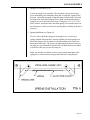
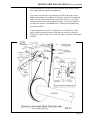
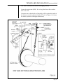
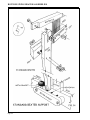
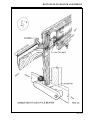
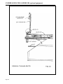
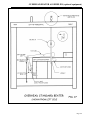
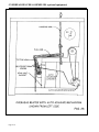
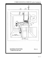
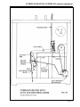
1
AVL
40
User's Manual
AVL Looms
3851 Morrow Lane, Suite 9
Chico, CA 95928-8305 U.S.A.
530 893-4915
530 893-1372 (fax #)
[email protected] (e-mail)
www.avlusa.com
Copyright © 2002
All Rights Reserved Worldwide
TABLE OF CONTENTS
Figure Index
i
Introduction
Preface
•
How to Use this Manual
Loom Orientation
Tools Needed for Assembly
Full Frame Dobby Loom Parts List
1-1
1-2
1-2
1-3
1-4
1-6
Loom Assembly
•
Unpacking
•
Identifying Parts
1.)
Hardware - Identifying and Measuring
•
Bolt and Nut Hints
2.)
Identifying Side Frame Parts
•
Joining Side Frames
Upper and Lower Backs
Lower Front
Spring Lever Assembly
Spring Installation
Harness Pulley Support
Overhead Beater Axle Mounting Blocks
Beater Bumpers
2-1
2-1
2-1
2-1
2-3
2-4
2-5
2-5
2-6
2-7
2-7
2-8
2-9
2-9
Installation of the Dobby Head
1.)
Mounting the Dobby
3-1
3-1
Harness Tie-Up
Cable Retainers
Laying the Harness Cables
Replacing the Cable Retainers
Routing the Cables
Harness Assembly
Locating and Identifying the Harnesses
Preparing for Harness Assembly
Understanding Your Heddles
Harness Assembly (polyester heddles)
Metal Heddle Harness Frames
Attaching the Spring Lever Chain
Realigning the Dobby Cables
4-1
4-1
4-1
4-2
4-2
4-3
4-3
4-3
4-3
4-4
4-6
4-7
4-7
Page i
TABLE OF CONTENTS
Page ii
Installing Beams and Rollers
1.)
Rear Cloth Storage System Rollers
A.)
Upper and Lower Rollers
2.)
Installing the Standard "Plain" Warp Beam or
Half Yard Sectional Warp Beam
3.)
Warp Beam Handle
4.)
Installing the Second Plain Warp Beam
5.)
Installing Tension Box Mounting Studs
6.)
Installing the Sectional Beam
7.)
Installing the Cloth Beam
A.)
Removing the Cloth Beam Support
B.)
Assembling the Cloth Beam Handle
C.)
Assembling the Cloth Beam
5-1
5-1
5-1
5-1
5-1
5-3
5-3
5-3
5-4
5-4
5-4
5-5
Cloth Storage Assembly and Tie-Up
1.)
Cloth Storage Drum and Cloth Storage Ratchet
2.)
Cloth Storage Roller
3.)
Cloth Take-Up Drum Assembly
4.)
String Guide Pulleys
5.)
Weight Track and Weight
6.)
Weight Stop
7.)
Routing the Cloth Storage Cord
6-1
6-1
6-3
6-3
6-3
6-4
6-6
6-6
Installing the Seat
7-1
Tension Arm Installation
1.)
Standard Warp Beam and Half Yard Sectional
Beam Tension Arm
2.)
Second Standard or Second Half Yard Sectional
Warp Beam Tension Arm
3.)
One Yard Sectional Beam Tension Arm
8-1
Bottom Swing Beater Assemblies
•
Beater Supports
1.)
Standard Beater
2.)
Single Box Flyshuttle Beater
Overhead Beater Assemblies
1.)
Overhead Standard Beater
2.)
Overhead Single Box Flyshuttle Beater
3.)
Overhead Double Box Flyshuttle Beater
•
Multiple Box Flystring Tie Up Assembly
Vertical Pull Flystring Tie Up
4.)
Overhead Four Box Flyshuttle Beater
Vertical Pull Flystring Tie Up
9-1
9-1
9-1
9-4
9-7
9-7
9-17
9-27
9-37
9-37
9-41
9-53
8-1
8-3
8-5
TABLE OF CONTENTS
Raddle
Tension Box
1.)
Mounting the Track Arms
2.)
Mounting the Track
3.)
Mounting the Tension Box
10-1
10-1
10-1
10-1
10-2
Compu-Dobby II Installation and Assembly Instructions
•
Introduction
•
Install the Solenoid Box
•
Cables and Component Box
•
Internal Sensor Wire
•
Serial Cable (RS-232)
•
Component Box to Solenoid Box
•
Power Extension Cord
•
Power Cord
•
Set-Up Your Computer
•
Secure the Cords
•
Surge Protector
•
IMPORTANT: Solenoid Box Adjustment
•
To Adjust
•
Maintenance
•
Clean the Filters
•
Fuse Replacement
•
Troubleshooting
•
Solenoid Box Adjustment
CD-1
CD-1
CD-2
CD-3
CD-3
CD-3
CD-4
CD-4
CD-4
CD-5
CD-6
CD-6
CD-6
CD-6
CD-8
CD-8
CD-8
CD-9
CD-9
Page iii
FIGURE INDEX
FIGURE INDEX
Figure #
Drawing Title
1
2
3
4
5
6
7
9
10
Full Frame Dobby Loom
Tools Needed For Assembly
Hardware Identification Chart
Assembling Lower Left Back Corner
Side Frames, Rear And Front Of Loom
Spring Installation
Harness Pulley Support Installation
Beater Bumper Block
Dobby - Front View
Yoke Cable for UDL 40
Cutting the Heddles Apart
Metal Heddle Frame
Warp Beam and Handle Mounting Assembly
Cloth Beam Assembly
Cloth Storage Drum
Cloth Storage Weight Assembly
Cloth Storage
Standard Beam Tension Arm
Second Plain Beam Tension Arm
One Yard Sectional Beam Tension Arm
Standard Beater Support
Single Box Flyshuttle Beater
Overhead Standard Beater, Front
Overhead Standard Beater, Left
Overhead Beater with Automatic Advance
Mechanism
Overhead Beater Pivot Bracket
Overhead Beater Adjustment Base
Overhead Beater Racking Position
Overhead Beater Pivot Bracket
Overhead Beater Adjustment Base
Overhead Single Box Flyshuttle Beater, Front
Overhead Single Box Flyshuttle Beater, Left
Overhead Beater with Automatic Advance
Mechanism
Overhead Beater Racking Position
Overhead Beater Pivot Bracket
Overhead Beater Adjustment Base
Overhead Double Box Flyshuttle Beater, Rear
Overhead Double Box Flyshuttle Beater, Left
Overhead Beater with Automatic Advance
Mechanism
Vertical Pull Upper Pulley Assembly
Drop Box Assembly
Overhead Beater Racking Position
11
12
16
17
18
19
20
21
22
23
24
25
26
27
28
29
30
31
29
30
32
33
34
35
29
30
36
37
38
39
40
41
Page #
1-5
1-4
2-2
2-3
2-4
2-7
2-8
2-9
3-1
4-1
4-4
4-6
5-2
5-4
6-1
6-4
6-5
8-1
8-3
8-5
9-2
9-5
9-8
9-9
9-10
9-11
9-12
9-13
9-17
9-18
9-19
9-20
9-21
9-22
9-27
9-28
9-29
9-30
9-31
9-32
9-32
9-33
Page i
FIGURE INDEX
Figure #
Drawing Title
29
30
39
41
42
43
44
45
Overhead Beater Pivot Bracket
Overhead Beater Adjustment Base
Vertical Pull Upper Pulley Assembly
Racking Position Overhead Beater
Overhead Four Box Flyshuttle Beater, From Rear
Overhead Four Box Flyshuttle Beater, From Front
Overhead Four Box Flyshuttle Beater, From Left
Overhead Beater With Automatic Advance
Mechanism
Four Box Vertical Pull Backplate Assembly
Four Box Flyshuttle Beater Shift Handle
Four Box Shift Handle Cable To Drop Box
Solenoid Box Installation
AVL 40 Component Box Placement
46
47
48
Page ii
Page #
9-41
9-42
9-43
9-44
9-45
9-45
9-46
9-47
9-48
9-49
9-49
CD-1
CD-3
INTRODUCTION
INTRODUCTION
No doubt you want to get to the business (and the fun) of setting up your
loom. O.K., but first a few words of advice: There’s probably some of you
who don’t like to read directions or think that this manual is entirely too thick
and you don’t have time to read all the way through it. Please read through
the directions and follow them step-by-step with us. You will spend less time
and will end up with the loom looking and working as we have planned it.
There are those of you who have never touched a hex bolt and are not even
sure you know what one is. To you, we say, “Try it. If you follow the instructions step-by-step and take your time, you will be surprised at what you can
do.”
To members of the two above camps, and to all those in between, we say,
“Stick with it and we are certain you will find this to be a good experience and
a great way to get to know your loom.” Remember, if you are at all serious
about weaving, a thorough knowledge of your equipment is vital. So think of
this as an opportunity, not as a liability.
Page 1-1
PREFACE
The two purposes of this assembly manual are:
HOW TO USE
THIS MANUAL
1.)
To assist the loom owner in assembling and getting to know her/his
loom by providing complete and detailed instructions and drawings.
2.)
To allow the weaver to enjoy a well cared for and properly functioning
loom for many years by providing a care and maintenance schedule.
This manual was written to be read and followed from beginning to end.
Some of the information is quite basic and there are those of you who will
want to skip those sections entirely. Instead of skipping them, we suggest you
skim them (there just may be important information hidden right in the middle
of a very basic section).
All of the major sections are in the index, in case you need to refer back for
any reason.
We at AVL know that a picture is indeed worth a thousand words and, for that
reason, have included many detailed drawings to help clarify our instructions.
Since all of our parts are not numbered, you can use these drawings to help
identify certain parts. You will find Figure #1 to be particularly useful and
may wish to pin or tape it up in a handy place for easy reference. This drawing shows all the major parts of the loom and is valuable in determining the
relative position of parts. The parts list following Figure #1 should be kept
within easy reach as well.
This manual includes assembly instructions for sixteen or twenty-four harness
full frame dobby looms. Also included are instructions for options such as:
•
•
•
•
•
second plain beams
sectional beams
tension box
raddle
single and multiple box flyshuttle beaters
You need only read the sections for the kind of loom or option(s) you have
ordered.
Page 1-2
LOOM ORIENTATION
Before we really get going, there are a few things you should know in order to
better understand our instructions. First, and very important, is what we mean
when we say “the front of the loom”. The front of the loom is the end where
the seat is; the back of the loom then, is where the warp beam is. Everything
is oriented as if you were sitting in the weaving position. The right side of the
loom is the side to your right as you are sitting at the loom and the left side is
to your left. A piece marked “bottom” would, of course, go toward the floor.
There is a full drawing of the loom on the following page. This can be referred to as often as necessary to obtain relative placements of assemblies.
Following this is a parts number list. Since this list includes the names and
part numbers of all parts and assemblies, you may need to refer back to it.
Study all the drawings carefully and make certain that your assembly looks
like the one in the drawings before continuing.
Where applicable and necessary on the drawings, we have included a “weaver
symbol” to help clarify the view of the drawing. This symbol shows a weaver
seated at the weaving bench. Remember, the symbol is included only to help
clarify the orientation of the drawing. In the example shown, the weaver is
sitting, looking toward the right of the page. That would indicate that the
front of the loom is to the left of the page and the rear of the loom to the right.
If the arrow were pointing left, then the rear of the loom is to the left.
The right and left of the dobby head is oriented as if you were standing right
in front of it.
Page 1-3
TOOLS NEEDED FOR ASSEMBLY
There are a few tools you’ll need before we can get started. These are:
•
•
•
•
a phillips head screwdriver
a light hammer
a pair of pliers
four or six inch crescent wrench
A ratchet / socket set is very helpful and will speed up the assembly process,
but it is not essential, except in the case of mounting the tension box track
arms. For this assembly, you will need a 1/2” socket.
Page 1-4
LOOM ORIENTATION
Page 1-5
FULL FRAME DOBBY LOOM PARTS LIST
Page 1-6
Part #
Part Name
1R
2R
1L
2L
3R
3L
4R
4L
5
6
7
8R
8L
9R
9L
10
11
14
15
16
17
18
23
24
25
26
28
29
30
31
32
33
34
35
37
38
39
40
41
42
43
Right Front Vertical Side Frame
Right Rear Vertical Side Frame
Left Front Vertical Side Frame
Left Rear Vertical Side Frame
Right Top Horizontal
Left Top Horizontal
Right Lower Side
Left Lower Side
Upper Back
Lower Back
Lower Front
Right Cloth Beam Support
Left Cloth Beam Support
Right Vertical Support Assembly
Left Vertical Support Assembly
Harness Pulley Support Assembly
Spring Lever Assembly
Seat
Seat Support (optional)
Tension Arm Assembly, Standard
Harness Assembly (not shown)
Dobby Head
Warp Beam, Standard
Cloth Beam
Cloth Beam Ratchet Handle (not shown)
Upper and Lower Cloth Rollers
Rear Cloth Storage Roller
Cloth Storage Drum
Cloth Take-Up Drum
Cloth Take-Up Pulleys
Weight Track
Weight
Beater Supports (bottom swing)
Beater (not shown)
Second Warp Beam (not shown)
Second Warp Beam Tension Arm
Warp Beam Separation Roller(s) (one or two)
Beater Bumpers
Raddle
Warp Beam Handle (not shown)
Flyshuttle Cord Supports (not shown)
LOOM ASSEMBLY
LOOM ASSEMBLY
UNPACKING
The very first thing you need to do is take a nice, deep breath and slowly
exhale.
Now you can unpack your boxes being very careful not to throw any parts
away with the packing paper. Remove all strapping tape and bubble pack. Lay
all of the parts so that you will be able to identify each one as they are called for.
IDENTIFYING
PARTS
1.) Hardware Identifying and
Measuring
Pick up your bag marked "cross member hardware". Empty its contents onto a
table top. In the bag are:
•
•
•
•
•
•
•
•
•
hex bolts
carriage bolts
washers
hex nuts
square nuts
wing nuts
allen wrenches
two black knobs
possibly two machine screws.
Now look at the Hardware Identification Chart on the following page to familiarize yourself with the hardware.
Page 2-1
LOOM ASSEMBLY
Now you know all that you need to know about hardware to set up and maintain your loom.
Page 2-2
LOOM ASSEMBLY
Bolt and Nut
Hints
A.) If a bolt is a little tight going in the hole, give it a light, friendly tap with a
hammer.
B.) To start the threads on a square nut in a “nut access hole”, it is often
helpful to hold the nut in place with the end of a screwdriver or the tip of
your finger.
C.) Always have the larger “nut access hole” (see Figure #4) facing toward
the inside of the loom unless otherwise specified.
Page 2-3
LOOM ASSEMBLY
D.) Remember to put washers under the heads of the hex bolts and the exposed nuts (nuts that are not in access holes) to prevent damage to the
wood.
E.)
2.) Identifying
Side Frame Parts
Page 2-4
Carriage bolts usually require a tap or two from the hammer to seat the
square part of the bolt’s head into the wood.
The side frames are the parts that came in the biggest box. They are shipped
with the insides facing each other just as they will be when the loom is set up.
To determine which is the right side and which is the left, first orient them as
they are oriented in Figure #1, i.e., with the wider pieces at the back and at the
bottom. Now look at the front vertical piece. The right side will have a thin
dark strip of wood screwed to the inside face of it.
LOOM ASSEMBLY
JOINING SIDE
FRAMES
1.)
Locate the cross member hardware package and examine it. From its
contents, please locate the following items:
Dobby Loom
Hardware (with washers and nuts)
Location
1 - 5/16” x 4 1/2” Hex Bolt
Seat to Frame
1 - 5/16” x 3 1/2” Hex Bolt
Seat to Frame or Seat Support
or Flat Head Machine Screw
1 - 5/16” x 2 3/4” Carriage Bolt
Seat to Frame
4 - 5/16” x 3” Carriage Bolts
Beater Bumper Blocks to Loom
Frame
1 - 5/16” x 3 1/2” Hex Bolt
Seat Support to Lower Front
(40” and 48” only)
11 - 5/16” x 3 1/4” Hex Bolts
Most Crossmembers to Frame
2 - 5/16” x 3 3/4” Hex Bolts
Right End of Lower Front to Frame
1 - 5/16” x 3 3/4” Hex Bolt
Lower Right End of Upper Back
with Pulley to Frame
4 - 5/16” x 7 1/2” Hex Bolts
Harness Pulley Supports to Frame
4 - 5/16” x 3 1/4” Hex Bolts
Spring Lever Supports to Frame
The above hardware will be used to assemble the seat and crossmembers.
The remaining hardware will be used later.
2.)
Upper and Lower Backs
Locate the upper back (#5), the lower back (#6), the warp beam separation roller (#39), and, if you ordered a second beam, the second separation
roller (#39). It would be best if you had a helper for steps 2.) and 3.).
Page 2-5
LOOM ASSEMBLY
Using three 5/16” diameter x 3 1/4” hex bolts and the one 5/16” x 3 3/4”
hex bolt with the wooden pulley attached to it, attach the lower back to
the side frames using the longer bolt with the pulley as the lower bolt on
the right side (see Figure #5). Get the nuts started on the bolts, but don’t
tighten them yet (see Figure #4).
At this point, you must install the separation roller (#39). Refer to Figure
#5 for the relative position of this (or these) parts. If you have ordered one
beam, you will have received one separation roller. If that beam is a plain
beam or a half yard sectional beam, the separation roller will go in the
lower position as shown. On the other hand, if that beam is a one yard
sectional beam, the separation roller will go in the upper position. If you
have ordered two beams, you will have received two separation rollers
and you will install one in the upper and one in the lower position. To
install the separation roller, gently spread the side frames and insert the
rollers into the holes provided. Note that these holes do not go all the way
through the loom frame. If they do, you are using the wrong holes.
Now install the upper back (#5) using two 5/16” x 3 1/4” hex bolts,
washers, and square nuts, as shown in Figure #5. Tighten these now, as
well as the bolts and nuts on the lower back that we left loose in the
previous step.
3.)
Lower Front (#7)
Locate the lower front.
If your loom is a 40” or 48” model, this would be a good time to install
the seat support (#15) (see Figure #1). This part attaches to the lower
front with a 5/16” x 3 1/4” hex bolt, washer, and a square nut. If your
loom is a 60” or 72” model, proceed to the next paragraph.
Now the lower front assembly (#7) can be put on the loom. From the
outside of the loom, insert the two 5/16” x 3 1/4” hex bolts halfway into
the holes in the left side frame and two 5/16” x 3 3/4” hex bolts in the
right side frame where the lower front will be attached. Now kindly ask
your helper to prop up the front of the loom so that you can bolt the lower
front to the side frames. Go ahead and tighten the bolts on the left side,
but leave the ones on the right side a bit loose for now. A bracket will be
attached here later on. After the bolts are in place, gently let the loom
down again. Your loom should now look like the one in Figure #5.
Check to see that it does.
Page 2-6
LOOM ASSEMBLY
4.)
Spring Lever Assembly (#11)
Locate the spring lever assembly. This assembly consists of two long
pieces attached by rods with many short, thin, rectangular “spring levers”
between. Orient this assembly so that the stamp “bottom front” is toward
the front of the loom and facing the floor. Make certain that the shorter
spring levers are to the front of the loom. Using four 5/16” x 3 1/4” hex
bolts, washers, and square nuts, attach the spring lever assembly between
the side frames, a foot or so above the treadle pulley assembly as shown in
Figure #1.
5.)
Spring Installation (see Figure #6)
Now it’s time to hook the springs to the spring levers. Locate your
springs with the chain attached. Starting with the rear-most spring lever,
attach the spring to the wire hook on one side and the chain to the wire
hook on the other side. The chain is for adjusting the harness tension, so
for right now, just attach the last link to the wire hook and you can adjust
it if need be after you get your first warp on.
Make sure that the wire hooks are free to pivot on the metal pins in the
spring levers, otherwise they may get bent and won’t work properly.
Page 2-7
LOOM ASSEMBLY
6.)
Harness Pulley Support (#10)
Locate the harness pulley support. This assembly has three rows of
sixteen or twenty-four sheaves (pulleys) between two long crossmembers.
Using four 5/16” x 7 1/2” hex bolts, washers, and hex nuts (remember
that you’ll need washers under the hex bolts and the hex nuts), attach the
harness pulley support assembly to the side frame as shown in Figures #1
and #7. When correctly positioned, the left side will be flush with the left
side of the loom and the right side will stick out a few inches beyond the
right side frame pieces.
Page 2-8
LOOM ASSEMBLY
7.)
Overhead Beater Axle Mounting Blocks
(overhead beater only)
If your loom is to be equipped with an overhead beater, locate the package
from box #3 marked “Axle Blocks”. These blocks have a large hole in
them. Using the 5/16” x 5” carriage bolts in the package, mount these
blocks to the back edge of each rear side support (look ahead to Figure
#27). The heads of the carriage bolts should end up in the holes provided
for them on the front edge of each rear side support.
8.)
Beater Bumpers
Locate the beater bumpers (#40) (see Figures #1 and #9). The left is
stamped “L” and the right one is stamped “R”. They are each mounted to
the outside of the cloth beam supports with 5/16” x 3” carriage bolts,
washers, and hex nuts. Orient these beater bumpers so that the bumper
faces the front of the loom and the stamp faces the cloth beam support that
it will be mounted to. It is best to situate the carriage bolts so that the
washers and nuts are to the outside of the loom leaving the smooth head
of the carriage bolt on the inside of the loom frame. Now take a look at
your loom. Shaping up nicely, isn’t it?
Page 2-9
INSTALLATION OF
THE DOBBY HEAD
INSTALLATION OF THE DOBBY HEAD
1.)
Mounting the Dobby (#18)
On the back side of the dobby head you will find two bolts with washers
and hex nuts attached. Remove these washers and nuts making sure you
don’t unseat the carriage bolt heads. Check back to Figure #1 to see
where on the right side of the loom the dobby is mounted. Now lift up
the dobby unit and insert the protruding bolts into the corresponding
holes in the upper horizontal. Replace the washers and hex bolts and
tighten.
DOBBY - FRONT VIEW
Figure 10
Not to Scale
Page 3-1
HARNESS TIE-UP
AND ASSEMBLY
HARNESS TIE-UP
1.)
Harness cables already attached to the dobby head.
2.)
Cable Retainers
Mounted on top of the harness pulley supports are two wooden cross bars
with felt on their undersides. Using a phillips screwdriver, temporarily
remove these parts from the loom (see Figure #14).
3.)
Laying the Harness Cables
a.)
It is helpful for this next step to stand on a sturdy bench or chair. Set
the bench (or stand) between the lower front and the spring lever
support. Take hold of the number 1 harness cable and route it over
the pulley directly above it. Now bring that same cable (both ends)
over the number 1 pulley in the next set of pulleys. Repeat this
procedure with each of the remaining cables until all of the harness
cables are over all of the pulleys on the right side of the loom.
b.)
On larger width looms, you will also have yokes that connect the
harness wires to the harness. The yoke forms a "Y" by connecting
to a pair of screweyes.
YOKE CABLE FOR UDL 40
Berkeley Clip
Loop
Cable "Y" (8', 10',
12' looms)
Heddle
Page 4-1
HARNESS TIE-UP
4.)
Replacing the Cable Retainers
Now replace the cable retainer above the right set of pulleys, tightening
the screws so that it almost touches the pulleys. Don’t tighten the cable
retainers down far enough that they impede the movement of the pulleys.
It is essential to the proper functioning of the loom that they be free to
move. The cable retainer’s only purpose is to keep the cables from
jumping off of their pulleys.
5.)
Routing the Cables
Route the long ends of each of the cables over the far left of the pulleys.
After all cables are in place on each pulley, check to see that no cables
have crossed over each other. When you are certain that all is as it should
be, replace and tighten the left cable retainer as you did the right one.
Very good. Now on to the next step.
Page 4-2
HARNESS ASSEMBLY
Your loom may be equipped with either polyester or metal heddles. If your
loom has polyester heddles, start at step #1 below. If your loom has metal
heddles, skip ahead to step #5.
1.)
Locating and Identifying the Harnesses
Locate your harness sticks. They are long, thin pieces of wood with
screweyes on either end. There should be two groups. One group is
labeled “Tops”.
2.)
Preparing for Harness Assembly
You’ll need a table top for this next step. What you are going to do is
assemble the harnesses so that you can hang them on the cables.
Untape the bundle of harness sticks labeled “Tops”. Lay one of these on
the table, about a foot and a half in from the edge, with the screweyes
facing away from you.
3.)
Understanding your Heddles
Now locate the bag of heddles. Open it and look at your heddles, but
DO NOT remove the twist ties yet. Now locate your harness wires
(those are the long wires with copper stops near one end). Pick up a
bundle of heddles (there are approximately one hundred heddles in each
bundle) and hold them up by one end allowing the other end to hang
freely. Notice that there are four twist ties: two above the eye of the
heddle and two below the eye. Now, with the thumb and index finger of
your right hand, take hold of the upper right twist tie. Grasp the upper
left twist tie likewise with your left hand. Gently pull apart and notice
that all of the strings are captivated in either the right or left twist tie. If
you had four hands, you could grasp the bottom two twist ties in the
same manner. Then you would realize that there is indeed some order
and reason to this twist tie business. Into the space that is created by
pulling apart the twist ties, you will later insert a harness. Now that you
understand twist ties, you can see that if they were to be removed at this
point, you would experience chaos.
Page 4-3
HARNESS ASSEMBLY
4.)
Harness Assembly (polyester heddles)
With one group of the heddles in hand, return to the table with the
harness stick laying on it. Now insert the harness stick into the space
that was created by pulling apart the twist ties. As this point, you should
have an assembly made up of one harness stick (with screweyes facing
away from you) and one bundle of heddles (still possessing four twist
ties). Around the end of the harness should be the heddles. The heddles
should be oriented so that the eyes of the heddles are between you and
the harness stick. Notice that there is another “space” (between the twist
ties) that should be lying between the eyes of the heddles and you that
will accommodate another harness stick. O.K., now untape the bundle
of four harness sticks with the highest number. Take one of these harnesses to the table and with the screweyes facing you, insert the end of
the harness into the “space” in the heddles.
Page 4-4
HARNESS ASSEMBLY
Remember that each individual bundle contains one hundred heddles
(see Figure #11 for information as to where to cut the heddles).
Now pick up one of the harness wires and notice that there is a copper
stop near one end of it. That end is the top. Insert the bottom end of the
harness wire into the hole located at the end of the “top” harness stick
and down through the hole in the bottom harness stick. Repeat this for
the holes on the other end of the upper and lower harness sticks.
When you are certain you’ve done this correctly, you can untie the twist
ties. Now, if you will spread the heddles out along the lengths of the
harness sticks, you will notice that the heddles are all attached to one
another at the top or bottom. These connecting loops can be cut to make
threading easier. This will neither weaken or unravel the heddles (see
Figure #11).
(Another hint to make threading easier: while you have your heddles
spread out between two harnesses, mark above the eye of each one with
a colored pen. For instance, you may use four colors of pen and mark
the eyes on the heddles of harness 1 with purple, the eyes of harness 2
with red, the eyes of harness 3 with blue, and the eyes of harness 4 with
orange. Harness 5’s code color will be purple, harness 6’s code color
red, and so on. This makes it easier to tell which heddle belongs to
which harness and lessens the chance of threading errors.) Now pick up
your single harness assembly by the top harness (the one farthest away
from you on the table). Bring it over to your loom and hook up your last
harness cables (the ones closest to the back of the loom) to the
screweyes in the harness stick. There, you’ve completed one harness,
now the rest should be easy!
Repeat the steps above for each harness assembly. Always have the
“top” harness stick be the one furthest away from you with the
screweyes facing away.
Page 4-5
HARNESS ASSEMBLY
5.)
Metal Heddle Harness Frames
The metal heddle harness frames come fully assembled with the exception of the heddles themselves. The heddles should be installed onto the
harness frames before you hang them in the loom. To do this, remove
the clips from either end of the heddle rods and transfer the desired
amount of heddles onto each harness (see Figure #12). A pair of transfer
rods have been included to help with this process. To use them, simply
transfer the required amount of heddles onto each of these thin flexible
rods and then transfer the heddles onto the heddle rods. After replacing
the end clips on the heddles rods, you can hang the harness frames in the
loom by connecting them to the waiting ends of the harness cables.
Page 4-6
HARNESS ASSEMBLY
6.)
Attaching the Spring Lever Chain
Now that you have assembled and hung all of your harness sticks, you
can hook them up to the spring lever chain. Near the outside end of each
spring lever is a chain. Please note the chain length varies as you move
further back, so the chains for harness #1 are about 6 1/4"; number 40's
are 7 1/2". Take the end link of your last spring lever on the left side and
hook it to the left screweye on the underside of the last harness stick.
Repeat for the right side. Now hook up all of the harnesses in the same
fashion.
7.)
Realigning the Dobby Cables
Your dobby head has been thoroughly tested at the AVL factory. At that
time, all of the cables were in their proper positions for use. Frequently
during shipping, however, the cables get jostled out of position and must
be straightened out. Now’s the time to do that. If you look up at your
dobby from underneath, you will notice that there are forty “fingers”,
each with a slot in the back side of it. There are also forty cables. There
should be one cable in each slot. If there isn’t, carefully rearrange them
so that the first cable is inside the first finger slot, etc.
Page 4-7
INSTALLING BEAMS
AND ROLLERS
INSTALLING BEAMS AND ROLLERS
1.)
Rear Cloth Storage System Rollers
A.) Upper and Lower Rollers
Now the roller tubes for the rear cloth storage system can be
installed. Here’s all there is to it:
Drop the upper cloth roller #26 into the slotted brackets (see Figure
#1 for placement). Then pick up the lower cloth roller (also #26)
and slip one end into its pinned slot. Pull the pin out of the other
bracket, drop the roller in, replace the pin, and you’ve done it.
At this point, you should have one roller left (#28). It is a bit
longer than the others and the open end of the roller has a small
notch in it. This tube will be installed later when we complete the
cloth storage system. You can set this part aside for now.
2.)
Installing the Standard “Plain” Warp Beam or Half Yard Sectional Warp
Beam
Install the standard plain warp beam in the lower two slots in the back
edge of the rear verticals (see Figure #16). The axle of the warp beam is
locked in place by the swiveling thumb screw latches. Included in the
contents of your hardware bag were two thumbscrews. These can now
be screwed slightly into the threaded inserts directly above each warp
beam slot. Lift up the warp beam, and with the (large, round) wooden
drum to the left side of the loom, seat the beam axle into the slots.
Swing the thumb screw latches around to meet the thumb screws. When
the latches have captivated the axle and are in a vertical position, tighten
them down.
3.)
Warp Beam Handle
Locate your warp beam handle (#42) (see Figure #16). Remove the
wing nut, washer, and bolt from the end of the handle. Place the hole in
the handle over the left end of the warp beam axle (making sure the
handle faces away from the loom). Line up the hole in the axle with the
carriage bolt and push it through. Reattach the washer and wing nut and
tighten.
Page 5-1
INSTALLING BEAMS AND ROLLERS
Page 5-2
INSTALLING BEAMS AND ROLLERS
4.)
Installing the Second Plain Warp Beam (optional equipment)
Install the second plain warp beam in the upper slots to the outside edge
of the rear verticals.
Loosen the black thumb screws enough so that the warp beam retainer
latches can be swung off to the side. Lift up the second warp beam, and
with the drum to the left side of the loom, seat the beam axle into the
slots. Swing the thumb screw latches around to meet the thumb screws
and when the latches have captivated the axle and are in vertical position, tighten them down.
5.)
Installing Tension Box Mounting Studs (optional equipment) (see Figure
#16)
If you’ve ordered a tension box and a sectional beam, you’ll need to
assemble the tension box track arm mounting studs to the side frame
prior to installing the sectional beam. Here’s how to do it. Out of your
tension box hardware bag, locate four 5/16” x 2 1/2” carriage bolts,
black discs and bushings, washers, and hex nuts. Insert the bolt through
the hole in the black disc so that the square part under the head of the
bolt makes contact with the countersunk portion of the disc. Slide the
black bushing onto the bolt. Now install this assembly, from the outside
of the loom, through one of the two holes provided on either rear vertical
(as shown in Figure #16). Slip the washer and nut on the inside of the
loom frame and tighten with a 9/16” socket wrench. Repeat this process
with the remaining three bolts.
6.)
Installing the Sectional Beam (optional equipment)
Install the sectional beam in the upper slots to the outside edge of the
rear verticals as shown in Figure #16. Loosen the black thumb screws
enough so that the thumb screw latches (also called warp beam retainer
latches) can be swung off to the side (this next step is easiest with the
help of a friend). Now lift the sectional beam up to the back of the
loom. Make sure that the large drum end of the beam is toward the left
side of the loom. Fit the axle into the slots and swing the thumb screw
latches around to meet the thumb screws. When the latches have captivated the axle, and are in a vertical position, tighten them down.
Page 5-3
INSTALLING BEAMS AND ROLLERS
7.)
Installing the Cloth Beam
A.) Removing the Cloth Beam Support
The cloth beam can be taken in and out of the loom simply and
easily by removing the upper section of either cloth beam support
(see Figure #17). In our example, we’ll remove the upper portion
of the left cloth beam support. Using your crescent wrench (or
socket), turn the upper bolt (shown clearly in the drawing) counter
clockwise until the nut disengages it. Pull the bolt until the upper
portion of the cloth beam support can be lifted out.
B.) Assembling the Cloth Beam Handle
Locate the cloth beam. It is the beam with the abrasive covering
and a ratchet on one end.
Now locate your cloth beam handle and wooden spacer ring (#25).
Insert the ratchet end of the cloth beam into the hole in the cloth
beam handle (with the wooden knob of the handle facing the inside
of the loom), then into the spacer ring. Insert the other end of the
cloth beam into the large hole in the upper portion of the cloth
beam support that was removed in step A.).
Page 5-4
INSTALLING BEAMS AND ROLLERS
C.)
Assembling the Cloth Beam
NOTE: Before installing the cloth beam to the loom, make certain that the
metal pawl is in the “off” position or pulled back around so that it is out of the
way of the cloth beam ratchet.
Slip the end of the cloth beam with the ratchet, handle, and spacer
ring into the corresponding hole in the cloth beam support that is
still on the loom. Now bring down the left end of the beam and fit
the pin (belonging to the lower portion of the cloth beam support)
into the slot (belonging to the upper portion). Reinstall the bolt
and tighten the square nut.
Page 5-5
CLOTH STORAGE
ASSEMBLY AND TIE-UP
CLOTH STORAGE ASSEMBLY AND TIE-UP
1.)
Cloth Storage Drum and Cloth Storage Ratchet
The cloth storage drum (#29) is a wooden drum about 5 1/2” in diameter
with a large flat wound return spring (like a clock spring) set into one
face of it. This drum is going to be attached to the outside face of the
right rear vertical of the loom frame. Refer to Figure #18 during this
assembly.
Page 6-1
CLOTH STORAGE ASSEMBLY AND TIE-UP
A.) Locate the cloth storage ratchet. It is a steel axle with an aluminum ratchet and knob attached to one end of it. This axle should
now be inserted into the metal sleeve that is about one foot up from
the floor on the right rear vertical frame piece. Insert the axle from
the inside. Check to see that the wooden pawl (called the cloth
storage pawl) on the inside of the loom frame engages with the
teeth of the ratchet.
B.) Now locate the previously mentioned cloth storage drum. Notice
that there are two pieces of tape holding the spring in place. Do
not remove this tape yet. It should stay in place until the drum is
firmly attached to the loom frame.
Before you put the drum on the loom, place a washer on the axle as
it sticks out from the outer face of the loom frame. Now take a
look at the flat wound return spring in the drum. Notice how it is
attached to the drum at its inner end by a small steel pin. Also
notice how there is a similar hook shaped bend at the outer end of
the spring. Now look at the loom frame and notice a small steel
pin just above the drum axle that you just installed. By now
you’ve probably figured out that the hooked end of the spring and
this steel pin will come together as part of this assembly. We’re
telling you this now because it’s hard to see it happening when the
drum is actually being put on the loom.
C.) Speaking of that, you can now place the drum on the axle that you
installed in step A.). Carefully remove the tape making certain that
the spring stays inside of the drum. At this point, the trick is to get
the hook at the outer end of the spring to catch on the steel pin
above the axle. The best way to do this is to position the drum on
the axle so that the hook is just a bit to the left of the steel pin and
then hold the drum against the outer face of the loom frame while
slowly turning the drum in a clockwise direction making sure that
the pin is between the outer coil of the spring and the outer edge of
the hollowed out portion of the wooden drum. You will know right
away if the hook caught on the pin because if it did catch, the drum
will want to unwind in a counter clockwise direction (which is just
what it is supposed to do). Once you have gotten your drum to
behave properly, you will need to install the remaining washer and
a 3/8” stop collar onto the end of the steel axle with the knot facing
the inside of the loom. Tighten the set screw of the stop collar
(using an allen wrench) onto the flat portion of the axle making
sure to leave a small amount of clearance so that the drum and axle
assembly can rotate freely. Leave the cord wrapped around the
drum for now. It will be dealt with soon.
Page 6-2
CLOTH STORAGE ASSEMBLY AND TIE-UP
2.)
Cloth Storage Roller
Locate the cloth storage roller (#28). It has a metal axle sticking out one
end and a notch cut out of the other end. Line the notch up with the pin
on the small knob shaped portion of the cloth storage ratchet (see Figure
#18). Push the roller toward the ratchet until the roller seats itself
against the ratchet face. Slip the other end of the roller into the angled
slot on the bracket on the left rear vertical.
3.)
Cloth Take-Up Drum Assembly
Locate the cloth take-up drum assembly (#30). It is a wooden drum with
two grooves around its perimeter. There is a steel axle attached to this
drum with a small crank attached to it. Using an allen wrench, remove
the crank and one of the plastic spacers from the axle. From the outside
of the loom, insert the axle of the drum through the metal bushing
located near the front end of the right top horizontal of the loom frame
(see Figure #20 for relative position). Slide the spacer and crank back
onto the axle with the knob facing the inside of the loom. Tighten the
set screw of the crank onto the flat portion of the axle in such a way that
the assembly can rotate freely.
4.)
String Guide Pulleys
Locate the remaining string guide pulley. It is a small, wooden pulley
like the one that is mounted near the bottom of the right rear vertical (as
shown in Figure #18). This pulley will go on the outer face of the
bottom right horizontal frame piece directly below the cloth take-up
drum that you just installed. Attach this pulley with the 5/16” x 2 1/4”
hex bolt provided. Make sure that there is a washer on either side of the
bronze bushing. The nut should end up with a washer on the inside of
the loom frame.
Page 6-3
CLOTH STORAGE ASSEMBLY AND TIE-UP
5.)
Weight Track and Weight
Locate the weight track. It is a long thin piece of wood with two small
rubber bumpers at one end of it. This track is already attached to the
outer face of the right front vertical frame piece.
Page 6-4
CLOTH STORAGE ASSEMBLY AND TIE-UP
Now locate the weight. It is a heavy black rectangular piece of steel
with two wooden runners attached to it. Take the weight to the bottom
of the track and guide the weight onto the loom so that the track is
between the two runners on either side of the weight (see Figures #19
and #20) making sure that the end with the cord coming from it is
toward the top. This cord will be attached soon.
Page 6-5
CLOTH STORAGE ASSEMBLY AND TIE-UP
6.)
Weight Stop
The weight stop is a small metal bracket with two rubber bumpers
attached to it. It will also be attached to the outside face of the right
front vertical just below the weight track. While holding the weight up a
few inches so it is out of the way, loosen the two bolts that hold the right
end of the lower front in place. Back off the bolts just enough so that
you can slide the slotted edge of the bracket behind the heads of the
bolts. Then retighten the bolts and gently set the weight down on this
floor protecting weight stop.
7.)
Routing the Cloth Storage Cord
Unwrap the cord that comes from the weight and bring the end of it
straight up to the cloth take-up drum. Feed the end of the cord through
the small hole in the outer groove of the drum (see Figure #19). Pull the
cord through the access hole on the inner face of the drum (this may
require a slight rotation of the drum) and tie a double overhand knot at
the end of the string. Now turn the crank counter clockwise (as you are
looking at it from the inside of the loom) and the weight will rise to the
top of the track. At this point, you engage the weight lock by turning the
knob above the tool holder to a horizontal position. This will hold the
weight in the upper position which is where you want it now.
Now go back to the cloth storage drum (at the rear of the loom) and
remove the tape that is holding the cord in place. Route the cord (as in
Figure #20) around the two lower string guide pulleys and clip it to the
cord hanging down from the cloth take up drum. There should be no
slack in the back drum. Tension has been loaded into the cloth storage
drum spring. The spring allows the weight to automatically rewind onto
the drum when the weight is returned to its upper position.
Unwinding the cord from the back cloth storage drum is somewhat akin
to pulling out the tape in a tape measure. As you pull the cord down and
around the two pulleys, you are increasing tension. If you were to let go,
it would wind back up like the tape measure. Clipping it puts the correct
tension on the system.
Page 6-6
CLOTH STORAGE ASSEMBLY AND TIE-UP
This completes the assembly of the cloth storage system. Please note that you
should never let the weight fall freely from its upper position. The weight
lock must always be used to hold the weight up when there is no cloth attached to the rear cloth storage roller. Always use the crank to lift the weight
up a bit before disengaging the weight lock.
NOTE: The retaining pin (with ring attached) can be removed from the cloth
storage ratchet to allow the cloth storage roller to spin. This is a handy feature
as it will allow you to unwind woven goods from the roller without having to
remove the roller from the loom. However, you must exercise extreme caution when doing this and never remove the pin unless the cloth storage weight
is either in the full up (and locked) or full down position. Otherwise, the
heavy weight will fall rapidly toward the floor.
Page 6-7
INSTALLING THE SEAT
INSTALLING THE SEAT
The seat (#14) can now be put into place (see Figure #1). The metal bracket
that is attached to it goes against the right front vertical with a 5/16” x 4 1/2”
hex bolt going through the front vertical, the bracket, and the seat itself. Use
the remaining bolt to attach the other end of the seat. If your loom is a 48”
model, this end of the seat will attach to the vertical seat support (#15) with a
5/16” x 3 1/2” flat head machine screw. If your loom is a 60” or 72” model,
the seat will go all of the way across the loom and attach to the left front
vertical with a 5/16” x 3 1/2” hex bolt. On the 60” and 72” looms, you will
notice that there are two holes in the right front vertical and one hole in the
left one for mounting the seat. An extra washer has been supplied with each
of these bolts so that a washer can also be placed between the front vertical
and the seat bracket. A 5/16” x 2 3/4” carriage bolt goes through the right
front vertical at the bottom of the bracket and is used to adjust the seat angle
for comfortable sitting (this seat can also be used as a back rest during threading ..... if you want to try it out as a back rest, just leave the carriage bolt to the
side for now and insert it following threading).
Page 7-1
TENSION ARM
INSTALLATION
TENSION ARM INSTALLATION (lower position)
1.)
Standard Warp Beam and Half Yard Sectional Beam Tension Arm
If you have ordered a standard warp beam or a half yard sectional beam,
you will have received tension arm #16. Proceed with this section.
If you have ordered only one beam and it is a one yard sectional beam,
you will have received tension arm #38S. Please skip this section and
go to 3.) One Yard Sectional Beam Tension Arm (upper position).
Orient the arm so that the face of the pulley will lie against the inside of
the left rear vertical as shown in Figure #21 (refer to Figure #1 to locate
the relative position of the lower tension arm).
Page 8-1
TENSION ARM INSTALLATION (lower position)
Remove the long bolt from the pulley end of the tension arm. Keeping
one washer on the bolt, push the bolt through the lower hole in the rear
vertical from the outside. Now put another washer on and slip the
tension arm, with its metal bushing, onto the bolt. Now another washer
and the hex nut, tighten it down, and it’s on.
After tightening, check to make sure the arm swings freely.
Now the cord tie-up can be attached.
The tension arm comes without the cord attached. Locate the tension
arm cord labeled #16. Attach this cord to the tension arm by removing
the shoulder bolt (the bolt near the wooden pulley) using a 5/32” allen
wrench and place this bolt through the looped end of the cord and
replace the bolt into the tension arm. Now (referring to Figure #21)
complete the cord tie-up. The cord comes away from the bolt in the
tension arm, over the top of the pulley, and down to meet the front side
of the drum on the warp beam. Now wrap the cord around the warp
beam drum three times with the first wrap toward the outside of the
loom. O.K., so far so good. The last portion of this tie-up is the tension
cord adjustment. At the very end of this cord assembly is an eyebolt.
Remove one hex nut and washer from the eyebolt and insert it from the
inside of the loom through the hole located in the upper rear portion of
the left bottom horizontal (see Figure #21). Replace the hex nut and
washer on the outside of the loom and tighten the eyebolt, placing it so
that it sets as far inward as possible (no threads protruding beyond the
nut on the outside of the loom). Now locate the tension arm weight. It
is a heavy black disk with a knob on one side of it. To attach the weight
to the arm, you will need to remove the stop screw from the end of the
tension arm using a 3/16” allen wrench. Place the arm through the
clamp on the side of the weight. Position it so the weight is on the same
side of the arm as the wooden disk is and the clamp faces the inside of
the loom. The weight will stay anywhere on the tension arm that you
place it as long as you tighten the knob on the weight. Be certain that
you replace the screw at the end of the tension arm. This screw serves as
a stop to keep the weight from accidentally slipping off. Proper adjustment of the tension arm will be covered later in the weaving section of
the manual.
Page 8-2
TENSION ARM INSTALLATION (lower position)
2.)
Second Standard or Second Half Yard Sectional Warp Beam Tension
Arm (upper position) (optional equipment)
If you have not ordered a second beam, proceed to the next section,
Bottom Swing Beater Assemblies. If you have ordered a second beam
and it is a one yard sectional beam, proceed to section 3.) One Yard
Sectional Beam Tension Arm (upper position). If you have ordered a
second beam and it is a standard beam or a half yard sectional beam,
proceed from here.
Locate the tension arm (#38). Orient the arm so that the face of the
pulley will lie against the inside of the left rear vertical as shown in
Figure #22 (refer to Figure #1 to locate the relative position of the upper
tension).
Page 8-3
TENSION ARM INSTALLATION (lower position)
Remove the long bolt (with its nut and washers) from the pulley end of
the tension arm. Put one of the washers back on the bolt and push the
bolt through the upper hole in the left rear vertical side frame member
from the outside. Now put another washer on and slip the tension arm
(with its metal bushing) onto the bolt. Now another washer, the hex nut,
tighten it down, and it’s on.
After tightening, check to make sure the arm swings freely. Now the
cord tie-up can be made. The tension arm comes without the cord
attached.
Locate the tension arm cord (#38P). Attach this cord to the tension arm
by removing the shoulder bolt (the bolt near the wooden pulley) using a
5/32” allen wrench and place this bolt through the looped end of the cord
and replace the bolt into the tension arm.
Now (referring to Figure #22) complete the cord tie-up. The cord comes
away from the bolt in the tension arm, over the top of the tension arm
pulley, then down to meet the front of the second warp beam drum.
Now wrap the cord around the warp beam drum three times (as shown)
with the first wrap toward the outside of the loom.
The last portion of this tie-up is the tension cord adjustment. At the very
end of this assembly is an eyebolt. Remove one hex nut and washer
from the eyebolt and insert it (from the inside of the loom) through the
hole located at the very back of the left top horizontal frame piece.
Replace and tighten the hex nut and washer on the eyebolt.
Now locate the tension arm weight. It is a heavy, black disk with a knob
on one side of it. To attach the weight to the arm you will need to
remove the screw from the end of the tension arm using a 3/16” allen
wrench. Place the arm through the clamp on the side of the weight.
Position it so the weight is on the same side of the arm as the wooden
disk is and that the clamp faces the inside of the loom. The weight will
stay anywhere on the tension arm that you place it as long as you tighten
the knob on the weight. Be certain that you replace the screw at the end
of the tension arm. This screw serves as a stop to keep the weight from
accidentally slipping off. Proper adjustment of the tension arm will be
covered later in the weaving section of the manual.
Page 8-4
TENSION ARM INSTALLATION (lower position)
3.)
One Yard Sectional Beam Tension Arm (upper position)
Locate the tension arm (#38S). It is a long, black bar with a wooden
disk at one end.
Orient the arm so that the face of the pulley will lie against the inside of
the left rear vertical as shown in Figure #23 (refer to Figure #1 to locate
the relative position of the upper tension arm).
Page 8-5
TENSION ARM INSTALLATION (lower position)
Remove the long bolt (with its nut and washers) from the pulley end of
the tension arm. Put one of the washers back on the bolt and push the
bolt through the upper hole in the left rear vertical from the outside.
Now put another washer on and slip the tension arm (with its metal
bushing) onto the bolt. Now another washer, the hex nut, and tighten it
down.
After tightening, check to make sure the arm swings freely.
Now the coated cable tie-up can be made. The tension arm comes
without the cable and tension adjustment attached.
Locate the tension arm cable (#38S). Attach this cable to the tension
arm by removing the shoulder bolt (the bolt near the wooden pulley)
using a 5/32” allen wrench and place this bolt through the looped end of
the cable and replace the bolt into the tension arm.
Now (referring to Figure #23) complete the cable tie-up. The cable
comes away from the bolt in the tension arm, over the top of the tension
arm pulley, and down to meet the front of the sectional beam brake
drum. Now wrap the cable around the sectional beam drum three times
(as shown) with the first wrap toward the outside of the loom.
The last portion of this tie-up is the tension cord adjustment. At the very
end of this assembly is an eyebolt. Remove one hex nut and washer
from the eyebolt and insert it (from the inside of the loom) through the
hole located at the very back of the upper left horizontal frame piece.
Replace and tighten the hex nut and washer on the eyebolt.
Now locate the tension arm weight. It is a heavy, black disk with a knob
on one side of it. To attach the weight to the arm, you will need to
remove the screw from the end of the tension arm using a 3/16” allen
wrench. Position it so that the weight disk is on the inner side of the
tension arm and the knob faces the outside of the loom. The weight will
stay anywhere on the tension arm that you place it as long as you tighten
the knob on the weight. Be certain that you replace the screw at the end
of the tension arm. This screw serves as a stop to keep the weight from
accidentally slipping off. Proper adjustment of the tension arm will be
covered later in the weaving section of the manual.
Now it’s time to sit back, have a cup of tea, and admire your loom. Coming
along quite nicely, isn’t it? Very good, now back to the fun.
Page 8-6
BEATER ASSEMBLIES
BOTTOM SWING BEATER ASSEMBLIES
If your beater is of the “Overhead” type, proceed to the next section titled
OVERHEAD BEATER ASSEMBLIES.
NOTE: Since the beater system uses a lot of carriage bolts, the following
information may be helpful. There is a square shape below the head of each
carriage bolt. This square portion does not fit easily into the pre-drilled holes.
You will find it necessary to tap these bolts into place to properly seat the
bolts. This will cause the bolt to “bite” into the wood and stay in place while
you tighten the nut.
Beater Supports
The beater supports can now be bolted to the loom. First locate your beater
supports (#34). There’s one for each side of the loom, so we’ll start on the
right side and you can refer to Figures #1 and #24 for correct placement.
Orient one of them so that the round spacers and metal pins are facing toward
the loom and the spacer with the threaded rod and metal bracket is toward the
front of the loom.
Remove the hex nut and washer from the rear spacer and insert the bolt
through the right lower horizontal. Slip the washer and nut back on and
tighten the nut just to the point where is almost cinches the two parts together.
You want to leave it a little bit loose so that the beater supports can pivot
during adjustment. Since the nut is a locknut, it will not loosen. Now locate
two 1 1/2’ long screws located in the beater hardware package. Position the
metal bracket that’s attached to the front of the beater support over the two
holes and insert the screws. Tighten them down. Repeat this process for the
left side.
1.)
Standard Beater
If you have ordered a single box flyshuttle beater, proceed to 2.) Single
Box Flyshuttle Beater (optional equipment).
Locate the following (see Figure #24):
•
•
•
•
•
•
shuttle race
beater top
two legs
reed
reed supports
hardware
Page 9-1
BOTTOM SWING BEATER ASSEMBLIES
Page 9-2
BOTTOM SWING BEATER ASSEMBLIES
Now pick up the shuttle race and orient it so that the lengthwise groove
is to the top and is facing toward the rear of the loom.
Position it in the loom so that it is resting on the cloth beam supports
between the cloth beam and the harnesses. Now empty your hardware
bag onto a table top. Pick up the four 5/16” x 3 1/4” carriage bolts with
washers and hex nuts.
Now locate the beater legs. Notice that they have been marked to
designate left and right. Using each leg, orient them so that, with the
bottom slot riding in the center pin on the beater support, the tapered
side of each leg faces away from the loom. Insert the bolts, from the
front of the race, through the race, and into the corresponding holes in
the beater leg. These are the two innermost holes. The two outer holes
on each end will not be used on this assembly. They are for a single or
multiple box flyshuttle beater should you ever care to adapt your loom.
Attach the washers and nuts and tighten slightly. Repeat this procedure
for the other side of the loom making sure that the tapered side of the leg
is always facing away from the loom. Attach the washers and nuts
leaving them loose for the moment.
From your hardware package, locate either six, seven, or nine (depending upon the width of your loom) 5/16” x 3” carriage bolts with washers
and wing nuts attached. Remove the washers and wing nuts. Push the
carriage bolts through the race so that their heads sit flat on the front of
the beater race (don’t be afraid to use a hammer to tap these bolts in
place). Now carefully slide the reed support onto these bolts so that the
lengthwise groove in it faces the groove in the race. Leave enough room
so that you can fit the reed between the race and the reed support. Once
the reed is in and centered, the washers and wing nuts can be fitted onto
the carriage bolts and tightened.
Now orient your beater top so that the groove is facing down and the cut
outs at either end are facing toward the rear of the loom. Insert 1/4” x 2
1/4” carriage bolts into the holes located at each end, starting them from
the front. Placing the beater top over the race and reed, slide the bolts
into the slots at the top of the beater legs and once the reed is securely
inside the groove in the beater top, attach the washers and wing nuts and
tighten them.
At this point, you should center the beater assembly in the loom and
tighten the bolts that attach the beater legs to the shuttle race. Centering
the beater will insure that the legs will not rub on the loom frame.
Page 9-3
BOTTOM SWING BEATER ASSEMBLIES
2.)
Single Box Flyshuttle Beater (optional equipment)
NOTE: The single box flyshuttle system now incorporates removable
shuttles boxes. This allows the weaver to completely remove the boxes and
flystring tie-up from the loom any time that an extensive amount of
handshuttle weaving becomes necessary. It also makes it much easier to
convert any other AVL beater system to a single box flyshuttle beater.
Locate the following (see Figure #25):
•
•
•
•
•
•
•
shuttle race
beater top
two legs
hardware
string tie-up
reed
reed support
Pick up the race and orient it so that the lengthwise groove is facing
toward the rear of the loom and the shorter flyshuttle box sides are
towards the front. Now lay the race across the loom in the approximate
position it will be when in use.
Empty your hardware bag on a table top. Separate the 5/16” x 3 1/4”
carriage bolts, washers, and hex bolts. Look at your beater legs. They
are identified as to left and right by a stamp. Orient it so that the cut out
section faces the front of the loom and the tapered side of the leg is to
the outside. Position the small notch located at the bottom end of the leg
over the center pin in the beater support. Now attach the race to the leg
using two of the 5/16” x 3 1/4” carriage bolts. Slip on the washers and
nuts and attach loosely. Repeat the procedure above for the left side
making sure the tapered side of the beater leg faces away from the loom.
Leave these nuts loose for the moment.
From your hardware package, locate either six, seven, or nine (depending upon the width of your loom) 5/16” x 3” carriage bolts with washers
and wing nuts attached. Remove the washers and wing nuts. Push the
carriage bolts through the race so that their heads sit flat on the front of
the beater race (don’t be afraid to use a hammer to tap these bolts in
place). Now carefully slide the reed support onto these bolts so that the
lengthwise groove in it faces the groove in the race. Leave enough room
so that you can fit the reed between the race and the reed support. Once
the reed is in and centered, the washers and wing nuts can be fitted onto
the carriage bolts and tightened.
Page 9-4
BOTTOM SWING BEATER ASSEMBLIES
Page 9-5
BOTTOM SWING BEATER ASSEMBLIES
Now orient your beater top so that the groove is facing down and the cut
outs at either end are facing toward the rear of the loom. Insert 1/4” x 2
1/4” carriage bolts into the holes located at each end, starting them from
the front. Placing the beater top over the race and reed, slide the bolts
into the slots at the top of the beater legs and, once the reed is securely
inside the groove in the beater top, attach the washers and wing nuts and
tighten. Now securely tighten the carriage bolts that attach the legs to
the race.
At this point, you should center the beater assembly in the loom and
tighten the bolts that attach the beater legs to the shuttle race. Centering
the beater will insure that the legs will not rub on the loom frame.
Take the string tie-up and handle from its bag. As you can see, there are
three screweyes coming out of the handle. One at the top and two at the
sides. Hold the handle up by the clip attached to the string at the top of
the handle. This clip will get attached to the screweye that is located in
the beater hardware package. However, the screweye must first be
screwed into the center hole on the underside of the front harness pulley
support. Now screw the screweye in so that no screw threads are showing. Then attach the clip to it.
At this point, there are two pickers hanging below the handle. Take one
of these and orient it so that the leather loop is toward the bottom. Now
take it to the very outside of the race on the right side. Slide the picker
with the leather loop down and toward the outside into the slots between
the box sides. Repeat for the other side making sure that the left picker
loop is down and toward the outside.
Now locate the flystring supports (#43). These are two small, wooden
bars that each have a screweye at one end. They were packed with the
flystring tie-up. These flystring supports should be attached to the inside
face of each top horizontal side frame piece. Insert two 5/16” x 2 1/4”
carriage bolts from the outside of the two holes on each top horizontal
directly above the beater assembly. These supports should hang down
from the top horizontal with the screweye end on the bottom. Tighten
the supports securely with washers and hex nuts.
Attach the clip at the end of the cord coming from the picker to the
screweye on the left and right flystring supports that you just installed.
Now notice that there is a snubber attached to the front box on each side
of the race (the snubbers are the small, round, wooden pieces above each
shuttle box). The cord should go over each snubber.
This completes the assembly of the single box flyshuttle beater.
Page 9-6
OVERHEAD BEATER ASSEMBLIES (optional equipment)
NOTE: Since the beater system uses a lot of carriage bolts, the following
information may be helpful. There is a square shape below the head of each
carriage bolt. This square portion does not fit easily into the pre-drilled holes.
You will find it necessary to tap these bolts into place to properly seat the bolts.
This will cause the bolt to “bite” into the wood and stay in place while you
tighten the nut.
1.)
Overhead Standard Beater (optional equipment)
If you have ordered the overhead single box flyshuttle beater, proceed to
section 2.) Overhead Single Box Flyshuttle Beater (optional equipment).
If you have ordered the overhead double box flyshuttle beater, proceed to
section 3.) Overhead Double Box Flyshuttle Beater (optional equipment).
If you have ordered the overhead four box flyshuttle beater, proceed to
section 4.) Overhead Four Box Flyshuttle Beater (optional equipment).
This system is shipped partially disassembled to facilitate packing. Follow
the instructions below to complete the assembly. Please refer to Figures
#26 through #31 for help with terminology and locations. They are all
located together for ease in locating them as they will need to be referred
to many times.
A.) The first step of this assembly is to mount the beater retainer to the
inside face of the left cloth beam support. Insert the #12 x 1 1/2” flat
head wood screw through the beater retainer and into the pre-drilled
hole on the inside of the left cloth beam support (see Figure #27).
Leave the screw just loose enough so that the retainer is allowed to
pivot around the screw.
B.) The next step of this assembly is to mount the beater adjustment
bases to the upper edge of each top horizontal on the assembled side
frames of your loom (see Figures #27 and #30). Attach these parts
using the four #8 x 3/4” pan head wood screws. Making sure that
the notched ends of these parts face upward, insert the screws from
the top of the beater adjustment bases and screw them into the predrilled holes on the top edge of each top horizontal (see Figure #30).
Tighten the four screws securely.
C.) Locate the two uprights (see Figures #26 and #29). Lay the uprights
on the floor spaced apart a distance that is approximately equal to
the width of your loom. The ends with the metal brackets will be
the top of this assembly. Now lay the shuttle race on top of the two
uprights so that it covers the two holes in the face of each upright as
shown in Figure #26.
Page 9-7
OVERHEAD BEATER ASSEMBLIES (optional equipment)
Page 9-8
OVERHEAD BEATER ASSEMBLIES (optional equipment)
Page 9-9
OVERHEAD BEATER ASSEMBLIES (optional equipment)
Page 9-10
OVERHEAD BEATER ASSEMBLIES (optional equipment)
Page 9-11
OVERHEAD BEATER ASSEMBLIES (optional equipment)
Page 9-12
OVERHEAD BEATER ASSEMBLIES (optional equipment)
Page 9-13
OVERHEAD BEATER ASSEMBLIES (optional equipment)
There is a groove cut in one side of the shuttle race which must be
oriented to the top and back of the race which means that it should
(for now) be facing down toward the floor. Attach the shuttle race
to the uprights with two 5/16” x 3 1/4” carriage colts (one on each
side). You will see that there are two holes on each end of the
shuttle race that correspond with the two holes on either upright.
For now, only the innermost hole on each end will be used. The
outer holes take a different bolt and will be used later. Attach the
washers and hex nuts to these carriage bolts, but do not tighten them
just yet as you will be making some adjustments shortly.
D.) Temporarily attach the beater top to the uprights with two 1/4” x 2 1/
4” carriage bolts with washers and wing nuts behind the uprights.
The beater top should be attached to the same side of the uprights as
the shuttle race with the long groove facing downward. Insert the
carriage bolts through the holes near each end of the beater top and
then through the slots that are located just below the metal bracket of
each upright. You do not need to put the beater top on now, but if
you do, it will help in creating proper alignment of the beater parts.
Page 9-14
E.)
Place the beater in the loom. For now, it will just sit in the loom
resting on top of the cloth beam supports just in front of the harnesses. The assembly may tend to fall forward or backward, but
don’t worry about that. You now have some other assemblies to
complete before actually attaching the beater.
F.)
The next step is to mount the hanging arms to the uprights on the
shuttle race assembly (see Figures #26 and #29). Using an 1/8”
allen wrench, remove the 3/8” stop collars from the metal shafts at
the tops of each upright and install the hanging arms onto these
shafts making sure that the right and left hanging arms are in their
proper positions. Also, be certain to include the small spacer as
shown. The stop collars are then replaced and tightened making
sure to leave enough clearance for this pivot point to swing freely.
Now look at the other end (the top) of one of the hanging arms.
Notice that there is a block of wood at this end that the beater
adjustment screw goes through. As shown in Figure #30, the foot at
the bottom end of the beater adjustment screw should be set into the
notch in the center of the beater adjustment base which you attached
to the loom in step B.) of this assembly. Once you have both of the
beater adjustment screws in place, the assembly of the hanging arms
is complete.
OVERHEAD BEATER ASSEMBLIES (optional equipment)
G.) Now you can insert the axle (a long, black pipe with holes at each
end) through each of the axle mounting blocks (see Figure #27) so
that the axle goes all of the way through the loom. There is no
particular right of left orientation for this axle as it is the same on
both ends. Now you can center the axle in the loom and place an
axle spacer (a round, wooden piece) on each exposed end of the
axle.
H.) Now locate the two tilting arm assemblies. They are stamped “L”
and “R” and are to be mounted at each end of the axle as shown in
Figures #27, #28, and #31. It is important to mount this assembly
correctly as shown with the push arms to the outside and the tilting
arms to the inside. The tilting arms are attached to the ends of the
axle with 5/16” x 2 3/4” hex bolts with washers and hex nuts
provided. Do not tighten these bolts yet. They will be part of a
critical adjustment coming up shortly. You will see a spring / cord /
eyebolt assembly hanging from each tilting arm. Just let them hang
for now. They will be attached later.
I.)
Next, mount each push arm to the back face of each upright (see
Figure #27) using two 5/16” x 4 1/2” hex bolts, washers, and square
nuts. These bolts go through the shuttle race and uprights and end
up in a square nut in the nut access hole of each push arm. You can
go ahead and tighten these bolts making sure that the outer face of
each push arm is relatively flush with the outer edge of their mating
uprights. This is also a good time to go ahead and tighten the other
bolts that we previously told you to leave loose. While tightening
these bolts, you should see that the beater is relatively square and
centered in the loom. The last bolts to tighten are the hex bolts that
we shall, for now, call the “Racking Adjustment Bolts” that connect
the tilting arms to the axle (see Figure #31). These bolts should be
tightened while the entire beater is being held firmly against the
beater bumpers. Figure #31 shows the beater being pushed toward
the front of the loom. In reality, you can align the beater by pushing
the tilting arms toward the front or the rear bumpers. The important
thing is to have the beater touching both the left and the right
bumpers at the same time.
As shown in Figure #31, push on the upper end of each tilting arm
and while the beater is in contact with both of the bumpers, securely
tighten the “racking adjustment bolts”. This operation will take two
people (unless you have a well trained dog who is not sleeping). If
the beater should come “out of square” in the future, if it should hit
one bumper before the other, you will need to repeat this adjustment,
loosening the bolts before you start and tightening them securely
after.
Page 9-15
OVERHEAD BEATER ASSEMBLIES (optional equipment)
J.)
Now is a good time to attach the beater return spring assembly. This
is the previously mentioned spring / cord / eyebolt assembly that
hangs from each tilting arm. To attach this assembly, simply remove
one hex nut and washer from each eyebolt and place the eyebolt
through the hole provided on each bottom horizontal of the side
frame assembly (see Figure #27). The eye of the bolt should be to
the outside of the side frame. Replace the washer and hex nut and
tighten securely.
This assembly is used to assist the weaver in returning the beater to
the back position. It is not necessarily intended to hold the beater in
this position as that is the purpose of the beater retainer.
The beater return spring assembly is adjustable. It is tightened by
pulling on the ends of the white cord while squeezing the black,
mini cord lock on the assembly. Whenever an adjustment is made
on one side of the beater, a similar adjustment should be made on the
other side as well. The amount of tension you set these springs at is
strictly a matter of preference. Generally speaking, the stronger the
tension, the harder you will have to pull against these springs during
the beat. At the same time, however, it will be easier to hold the
beater away from you while opening a shed and throwing the
shuttle. You may wish to experiment with these adjustments in order
to come up with a setting that works best for you and any particular
warp.
K.) Locate the reed support (the long, thin, wooden part with seven
holes and a slot similar to the one in the shuttle race). Attach the
reed support to the back of the shuttle race with the slot to the top
and facing the shuttle race using seven 5/16” x 3” carriage bolts
inserted from the front with washers and wing nuts behind. Before
attaching the nuts, install the bottom edge of your reed in the void
created by the slots in the reed support and shuttle race. Center the
reed between the two uprights and tighten the wing nuts.
L.)
There is a slot in the underneath side of the beater top which slides
over the top edge of the reed. Push the beater top down on the reed
and tighten the wing nuts which hold it in place.
This completes the assembly of your standard beater. Check your assembly
with Figures #26 through #31 to be certain you’ve gotten everything correct.
Page 9-16
OVERHEAD BEATER ASSEMBLIES (optional equipment)
2.)
Overhead Single Box Flyshuttle Beater
(optional equipment)
NOTE: The single box flyshuttle system now incorporates removable shuttle
boxes. This allows the weaver to completely remove the boxes and flystring
tie-up from the loom any time that handshuttle weaving becomes necessary. It
also makes it much easier to convert any other AVL beater system to a single
box flyshuttle beater.
This system is shipped partially disassembled to facilitate packing. Follow
the instructions below to complete the assembly. Please refer to Figures
#29, #30, and #32 through #35 for help with terminology and locations.
These are all located in one place for easy retrieval.
Page 9-17
OVERHEAD BEATER ASSEMBLIES (optional equipment)
Page 9-18
OVERHEAD BEATER ASSEMBLIES (optional equipment)
Page 9-19
OVERHEAD BEATER ASSEMBLIES (optional equipment)
Page 9-20
OVERHEAD BEATER ASSEMBLIES (optional equipment)
Page 9-21
OVERHEAD BEATER ASSEMBLIES (optional equipment)
A.) The first step of this assembly is to mount the beater retainer to the
inside face of the left cloth beam support. Insert the #12 x 1 1/2” flat
head wood screw through the beater retainer and into the pre-drilled
hole on the inside of the left cloth beam support (see Figure #33).
Leave the screw just loose enough so that the retainer is allowed to
pivot around the screw.
Page 9-22
OVERHEAD BEATER ASSEMBLIES (optional equipment)
B.) The next step of this assembly is to mount the beater adjustment
bases to the upper edge of each top horizontal on the assembled side
frames of your loom (see Figures #30 and #33). Attach these parts
using the four #8 x 3/4” pan head wood screws. Insert the screws
from the top of the beater adjustment bases and screw them into the
pre-drilled holes on the top edge of each top horizontal (see Figure
#30). Tighten the four screws securely.
C.) Locate the two uprights (see Figure #32). Lay the uprights on the
floor with the notched sides facing up. Space them apart a distance
that is approximately equal to the width of your loom. The ends
with the metal brackets will be the top of this assembly. The metal
rods should be pointing inward or toward each other. Now lay the
shuttle race assembly on top of the two uprights so that it covers the
two holes in the face of each upright as shown in Figure #32. There
is a groove cut in one side of the shuttle race which must be oriented
to the top and back of the race which means that it should (for now)
be facing the floor. The two rear plywood box sides should fit into
the notches on the front face of each upright. Attach the shuttle race
to the uprights with two 5/16” x 3 1/4” carriage bolts (one on each
side). You will see that there are two holes a foot or so from each
end of the shuttle race that correspond with the two holes on either
upright. For now, only the innermost hole on each side will be used.
The outer holes take a different bolt and will be used later. Attach
the washers and hex nuts to these carriage bolts, but do not tighten
them just yet as you will be making some adjustments shortly.
D.) Temporarily attach the beater top to the uprights with two 1/4” x 2 1/
4” carriage bolts with washers and wing nuts behind the uprights.
The beater top should be attached to the same side of the uprights as
the shuttle race with the long groove facing downward. Insert the
carriage bolts through the holes near each end of the beater top and
then through the slots that are located just below the metal brackets
of each upright. You do not need to put the beater top on now, but if
you do, it will help in creating proper alignment of the beater parts.
E.)
Place the beater in the loom. For now, it will just sit in the loom
resting on top of the cloth beam supports just in front of the harnesses. The assembly may tend to fall forward or backward, but
don’t worry about that. You now have some other assemblies to
complete before actually attaching the beater.
Page 9-23
OVERHEAD BEATER ASSEMBLIES (optional equipment)
F.)
The next step is to mount the hanging arms to the uprights on the
shuttle race assembly (see Figures #29 and #32). Using an 1/8”
allen wrench, remove the 3/8” stop collars from the metal shafts at
the tops of each upright and install the hanging arms onto these
shafts making sure that the right and left hanging arms are in their
proper positions. There is a screweye that has been mounted near
the middle of each hanging arm. These screweyes should face the
front of the loom. Also, be certain to include the small spacer as
shown in Figure #29. The stop collars are then replaced and tightened making sure to leave enough clearance for this pivot point to
swing freely. Now look at the other end (the top) of one of the
hanging arms. Notice that there is a block of wood at this end that
the beater adjustment screw goes through. As shown in Figure #30,
the foot at the bottom end of the beater adjustment screw should be
set into the notch in the center of the beater adjustment base which
you attached to the loom in step B.) of this assembly. Once you
have both of the beater adjustment screws in place, the assembly of
the hanging arms is complete.
G.) The next step is to mount the axle. To do this, you will need to
locate the axle mounting blocks that were installed previously onto
the rear side supports.
Now you can insert the axle (a long, black pipe with holes at each
end) through each of these blocks so that the axle goes all of the
way through the loom. There is no particular right or left orientation
for this axle as it is the same on both ends. Now you can center the
axle in the loom and place an axle spacer (a round, wooden piece)
on each exposed end of the axle.
H.) Now locate the tilting arm assemblies (#2). They are stamped “L”
and “R” and are to be mounted at each end of the axle as shown in
Figures #33, #34, and #35. It is important to mount this assembly
correctly as shown with the push arms to the outside and the tilting
arms to the inside. The tilting arms are attached to the ends of the
axle with 5/16” x 2 3/4” hex bolts with washers and hex nuts
provided. Do not tighten these bolts yet. They will be part of a
critical adjustment coming up shortly. You will see a spring / cord /
eyebolt assembly hanging from the end of each tilting arm. Just let
them hang for now. They will be attached later.
I.)
Page 9-24
Next, mount each push arm to the back face of each upright (see
Figure #33) using two 5/16” x 4 1/2” hex bolts, washers, and square
nuts. These bolts go through the shuttle race and uprights and end
up in a square nut in the nut access hole of each push arm.
OVERHEAD BEATER ASSEMBLIES (optional equipment)
You can go ahead and tighten these bolts making sure that the outer
face of each push arm is relatively flush with the outer edge of their
mating uprights. This is also a good time to go ahead and tighten
the other bolts that we previously told you to leave loose. While
tightening these bolts, you should see that the beater is relatively
square and centered in the loom. The last bolts to tighten are the hex
bolts that we shall (for now) call the “Racking Adjustment Bolts”
that connect the tilting arms to the axle (see Figure #35). These
bolts should be tightened while the entire beater is being held firmly
against the beater bumpers. (Figure #35 shows the beater being
pushed toward the front of the loom. In reality, however, you can
align the beater by pushing the tilting arms toward the front or by
pushing the race against the rear bumpers. The important thing is to
have the beater touching both the left and right bumpers at the same
time.)
As shown in Figure #35, push the tilting arms so that the beater race
contacts both front beater bumpers. Now tighten the “racking
adjustment bolts” securely. This operation will take two people. If,
in the future, the beater comes “out of square” - the beater contacts
one bumper before the other - you will need to loosen the “racking
adjustment bolts”, push the beater against both bumpers, and securely tighten the nuts.
J.)
Now is a good time to attach the beater return spring assembly. This
is the previously mentioned spring / cord / eyebolt assembly that
hangs from the end of each tilting arm. To attach this assembly,
simply remove one hex nut and washer from each eyebolt and place
the eyebolt through the hole provided on each bottom horizontal of
the side frame assembly (see Figure #33). The eye of the bolt
should be to the outside of the side frame.
This assembly is used to assist the weaver in returning the beater to
the back position. It is not necessarily intended to hold the beater in
this position as that is the purpose of the beater retainer.
The beater return spring assembly is adjustable. It is tightened by
pulling on the ends of the white cord while squeezing the black mini
cord lock on the assembly. Whenever an adjustment is made on one
side of the beater, a similar adjustment should be made on the other
side as well. The amount of tension you set these springs at is
strictly a matter of preference. Generally speaking, the stronger the
tension, the harder you will have to pull against these springs during
the beat.
Page 9-25
OVERHEAD BEATER ASSEMBLIES (optional equipment)
At the same time, however, it will be easier to hold the beater away
from you while opening a shed and throwing the shuttle. You may
wish to experiment with these adjustments in order to come up with
a setting that works best for you and any particular warp.
K.) Locate the reed support (the long, thin, wooden part with up to
seven holes and a slot similar to the one in the shuttle race). Attach
the reed support to the back of the shuttle race with the slot to the
top and facing the shuttle race using seven 5/16” x 3” carriage bolts
inserted from the front with washers and wing nuts behind. Before
attaching the nuts, install the bottom edge of your reed in the void
created by the slots in the reed support and shuttle race. Center the
reed between the two uprights and tighten the wing nuts.
L.)
There is a slot in the underneath side of the beater top which slides
over the top of the reed. Push the beater top down on the reed and
tighten the wing nuts which hold it in place.
M.) Take the string tie-up and handle from its bag. As you can see, there
are three screweyes coming out of the handle. One at the top and
two at the sides. Hold the handle up by the clip attached to the
string at the top of the handle. This clip will get attached to the
screweye that is taped to the bottom or side of the front harness
pulley support (see Figure #32). However, the screweye must first
be screwed into the hole on the underside of the harness pulley
support. Screw the screweye in so that no screw threads are showing. Then attach the clip to it.
At this point, there are two pickers hanging below the handle. Take
one of these and orient it so that the leather loop is toward the
bottom. Now take it to the very outside of the race on the right side.
Slide the picker (with the leather loop down and toward the outside)
into the slots between the box sides.
Now look up at the right hanging arm. About halfway down, there
is a screweye on the front face of the arm. The clip at the end of the
cord that attaches to the picker should be clipped to the screweye at
this point.
Page 9-26
OVERHEAD BEATER ASSEMBLIES (optional equipment)
Pick up the left picker. With the leather loop down and toward the
outside, slide it into the grooves in the left box sides from the very
outside of the race. Attach the clip at the end of the cord to the
screweye on the left hanging arm. Notice that there is a snubber
attached to the front box on each side of the race. The cord should
go over the snubbers (small, wooden spools above each shuttle box)
on each side of the loom.
This completes the assembly of your single box flyshuttle beater. Check your
assembly with Figure #32 to be certain you’ve gotten everything correct.
3.)
Overhead Double Box Flyshuttle Beater
(optional equipment)
This system is shipped partially disassembled to facilitate packing. Follow
the instructions below to complete the assembly. Please refer to Figures
#29, #30, and #36 through #41 for help with terminology and locations.
These drawings are located in one place for easy retrieval.
Page 9-27
OVERHEAD BEATER ASSEMBLIES (optional equipment)
Page 9-28
OVERHEAD BEATER ASSEMBLIES (optional equipment)
Page 9-29
OVERHEAD BEATER ASSEMBLIES (optional equipment)
Page 9-30
OVERHEAD BEATER ASSEMBLIES (optional equipment)
Page 9-31
OVERHEAD BEATER ASSEMBLIES (optional equipment)
Page 9-32
OVERHEAD BEATER ASSEMBLIES (optional equipment)
Page 9-33
OVERHEAD BEATER ASSEMBLIES (optional equipment)
A.) The first step of this assembly is to mount the beater retainer to the
inside face of the left cloth beam support. Insert the #12 x 1 1/2” flat
head wood screw through the beater retainer and into the pre-drilled
hole on the left cloth beam support (see Figure #37). Leave the
screw just loose enough so that the retainer is allowed to pivot
around the screw.
B.) The next step of this assembly is to mount the beater adjustment
bases to the upper edge of each top horizontal on the assembled side
frames of your loom (see Figures #30 and #37). Attach these parts
using the four #8 x 3/4” pan head wood screws. Insert the screws
from the top of the beater adjustment bases and screw them into the
pre-drilled holes on the top edge of each top horizontal (see Figure
#30). Tighten the four screws securely.
C.) Locate the two uprights (see Figure #36). Lay the uprights on the
floor spaced apart a distance that is approximately equal to the width
of your loom. These uprights are labeled left and right and it is
important that they be properly oriented. The ends of the uprights
with the metal brackets will be the top of this assembly. The metal
rods should be pointed inward or toward each other. There is a
metal pulley attached to the back face of each upright. These
pulleys should now be touching the floor. Lay the shuttle race on
top of the two uprights so that it covers the two holes in the face of
each upright. There is a groove cut in one side of the shuttle race
which must be oriented to the top and back of the race which means
that it should (for now) be facing down toward the floor. Attach the
shuttle race to the uprights with two 5/16” x 3 1/4” carriage bolts,
one on each side. You will see that there are two holes on each end
of the shuttle race that correspond with the two holes on either
upright. For now, only the innermost hole on each end will be used.
The outer holes take a different bolt and will be used later. Attach
the washers and hex nuts to these carriage bolts, but do not tighten
them just yet as you will be making some adjustments shortly.
D.) Temporarily attach the beater top to the uprights with two 1/4” x 2 1/
4” carriage bolts with washers and wing nuts behind the uprights.
The beater top should be attached to the same side of the uprights as
the shuttle race with the shift handle on top. You do not need to put
the beater top on now, but if you do, it will help in creating proper
alignment of the beater parts.
Page 9-34
OVERHEAD BEATER ASSEMBLIES (optional equipment)
E.)
Place the beater in the loom. For now it will just sit in the loom
resting on top of the cloth beam supports just in front of the harnesses. The assembly may tend to fall forward or backward, but
don’t worry about that. You now have some other assemblies to
complete before actually attaching the beater.
F.)
The next step is to mount the hanging arms to the uprights on the
shuttle race assembly (see Figure #29). Using a 1/8” allen wrench,
remove the 3/8” stop collars from the shafts at the tops of each
upright and install the hanging arms onto these shafts making sure to
put the right and left hanging arms in their proper positions. Also be
certain to include the small spacer as shown in Figure #29. The stop
collars are then replaced and tightened making sure to leave enough
clearance for this pivot point to swing freely. Now look at the other
end (the top) of one of the hanging arms. Notice that there is a
block of wood at this end that the beater adjustment screw goes
through. As shown in Figure #30, the foot at the bottom end of the
beater adjustment screw should be set into the notch in the center of
the beater adjustment base which you attached to the loom in step
B.) of this assembly. Once you have both of the beater adjustment
screws in place, the assembly of the hanging arms is complete.
G.) The next step is to mount the axle. To do this, you will need to
locate the axle mounting blocks attached previously to each rear side
support. Make certain that the axle hole is in the lower position as
shown in Figure #37 before you do this assembly.
Now you can insert the axle (a long, black pipe with holes at each
end) through each of these blocks so that the axle goes all of the
way through the loom. There is no particular right or left orientation
for this axle as it is he same on both ends. Now you can center the
axle in the loom and place an axle spacer (a round, wooden piece)
on each exposed end of the axle.
H.) Now locate the two tilting arm assemblies. They are stamped “L”
and “R” and are to be mounted at each end of the axle as shown in
Figure #37. It is important to mount this assembly correctly as
shown, with the push arms to the outside and the tilting arms to the
inside. The tilting arms are attached to the ends of the axle with 5/
16” x 2 3/4” hex bolts with washers and hex nuts provided. Do not
tighten these bolts yet. They will be part of a critical adjustment
coming up shortly. You will see a spring / cord / eyebolt assembly
hanging from the end of each tilting arm. Just let them hang for
now. They will be attached later.
Page 9-35
OVERHEAD BEATER ASSEMBLIES (optional equipment)
I.)
Next mount each push arm to the back face of each upright (see
Figure #37) using two 5/16” x 4 1/2” hex bolts, washers, and square
nuts. These bolts go through the shuttle race and uprights and end
up in a square nut in the nut access hole of each push arm. You can
go ahead and tighten these bolts making sure that the outer face of
each push arm is relatively flush with the outer edge of their mating
uprights. This is also a good time to go ahead and tighten the other
bolts that we previously told you to leave loose. While tightening
these bolts, you should see that the beater is relatively square and
centered in the loom. The last bolts to tighten are the hex bolts that
we shall (for now) call the “Racking Adjustment Bolts” that connect
the tilting arms to the axle (see Figure #41). These bolts should be
tightened while the entire beater is being held firmly against the
beater bumpers. Figure #41 shows the beater being held against the
front bumpers, although you may use either the front or back
bumpers for this adjustment. The important this is that both bumpers
are in contact with the beater at the same time.
Push the tilting arms toward the front of the loom so that both
bumpers contact the beater race. Now tighten the “racking adjustment bolts” securely. This operation will take two people. If, in the
future, the beater comes “out of square” - the beater contacts one
bumper before the other - you will need to loosen the “racking
adjustment bolts”, push the beater against both bumpers and securely tighten the nuts.
J.)
(See Figure #40.) Locate your left drop box assembly (they are
marked “L” and “R”). You will notice that there are two holes
through the back plate in the lower right corner and one in the upper
right corner with an intersecting hole coming from the right edge.
Looking at the left upright, you will find a horizontal hole through
the width of the upright just below the slot for the beater top. This
hole should be offset to the front of the shuttle race side of the
upright. Take a 5/16” x 4 1/2” hex bolt with a washer on it, insert it
through the hole in the upright from the inside through the hole in
the edge of the upper right corner of the drop box assembly and
thread it onto a square nut inserted in the nut access hole in the back
plate. Do no tighten this yet. Your drop box assembly should now
be attached to the upright with this one bolt with the moveable
boxes in the front.
K.) Attach the drop box assembly to the shuttle race with two 5/16” x 2
3/4” carriage bolts inserted from the front washers and hex nuts
behind the back plate. Now tighten all bolts holding the drop box
assembly to the beater.
Page 9-36
OVERHEAD BEATER ASSEMBLIES (optional equipment)
IMPORTANT: The face of the back plate must be precisely flush with the
face of the upright. Check this alignment by laying a straight edge across the
two surfaces.
L.)
Multiple Box
Flystring Tie Up
Assembly
Repeat this procedure for the right drop box assembly.
Vertical Pull Flystring Tie Up
M.) Locate the bag marked “Multiple Box Flystring Tie Up” and remove
its contents. These pieces can now be assembled on the loom as
shown in Figures #36 and #39. Use the mounting screws to attach
this assembly to the bottom edge of the pre-drilled front harness
pulley support as shown in the illustrations making sure that you
include the small wedge shaped piece of wood as part of this assembly. When assembled correctly, these pulleys should be angled
slightly toward the front of the loom. Also make certain that the
pulleys are to the rear or away from the weaver.
We suggest that you refer to Figures #36 and #39 before and during
this next step of the assembly. Remove the flystring tie up from the
bag. This tie up consists of a long dacron cord with a spring attached to one end of it.
You should now attach the loop at the free end of this spring to the
screweye that is affixed to the top of the left picker. The pickers are
the plastic “hammers” that slide horizontally through the drop box
assembly at each end of the beater assembly. Now route the end of
the cord under the pulley that is mounted on the rear face of the left
upright making sure that the cord goes between the pulley and the
attached retainer. From this point, route the cord up to the upper
pulley assembly that you just installed a few minutes ago. Route the
cord over both of these pulleys and continue routing the cord on the
right side of the loom exactly like you just did on the left side. Now
remove the receiving small spring from the bag and attach it to the
screweye. You now need to tie a good strong knot at the loop on the
free end of this spring. Where you tie this knot in relation to the end
of the cord will determine the operating height of the flystring
handle which you will attach in a moment. If you tie the knot very
near to the end of the cord, the handle will be at its lowest possible
position (if it went much lower, the flystring handle could collide
with the shift handle or beater top when it reached the bottom of its
throw). We suggest that you try this position first as a lower handle
position will generally be less fatiguing.
Page 9-37
OVERHEAD BEATER ASSEMBLIES (optional equipment)
Now go back to the upper pulley assembly where the cord passed
over both of the pulleys. You now want to route the cord down
between the two pulleys, taking up all of the slack and forming a
large loop at the center of the loom.
Locate the flyshuttle handle. It is a small, dark colored piece of
wood with a hole and a brass pin through the center of it. Form a
tight loop at the center of the cord that is now hanging below the
upper pulley assembly. Feed the loop down from the top of the
handle through the hole on either side of the brass pin that divides
the hole. Now feed the loop back through the hole on the other
side of the brass pin. Now form a larger loop (6” or so) and run it
back over either end of the handle. To do this, you actually put the
handle through this loop and bring the string of the loop all the way
back up to the top of the handle. Now pull straight down on the
handle, tightening the cord around the brass pin. This procedure
should automatically center the handle on the tie up.
Now you are going to tie an overhead knot in the cord between the
two upper pulleys (see Figure #39). To do this, make a small mark
on the cord where the cord goes between the two pulleys and pull it
straight down a few inches to where you can tie a simple overhand
knot with the handle already in place. Once the knot is tied, release
the cord and let it return to its resting position. If the knot was
placed correctly, the pickers should still return to the end of the
picker rod at each end of the beater and the cord should stop before
the knot stops the cord from moving any farther.
N.) Now is a good time to attach the beater return spring assembly. This
is the previously mentioned spring / cord / eyebolt assembly that
hangs from each of the tilting arms. To attach this assembly, simply
remove one hex nut and washer from the eyebolt and place the
eyebolt through the hole provided on each bottom horizontal of the
side frame assembly (see Figure #37). The eye of the bolt should be
to the outside of the side frame. Replace the washer and hex nut
and tighten securely.
This assembly is used to assist the weaver in returning the beater to
the back position. It is not necessarily intended to hold the beater in
this position as that is the purpose of the beater retainer.
Page 9-38
OVERHEAD BEATER ASSEMBLIES (optional equipment)
The beater return spring assembly is adjustable. It is tightened by
pulling on the ends of the white cord while squeezing the black mini
cord lock on the assembly. Whenever an adjustment is made on one
side of the beater, a similar adjustment should be made on the other
side as well. The amount of tension you set these springs at is
strictly a matter of preference. Generally speaking, the stronger the
tension, the harder you will have to pull against these springs during
the beat. At the same time, however, it will be easier to hold the
beater away from you while opening a shed and throwing the
shuttle. You may wish to experiment with these adjustments in order
to come up with a setting that works best for you and any particular
warp.
O.) Locate the reed support (the long, thin, wooden part with up to
seven holes and a slot similar to the one in the shuttle race). Attach
the reed support to the back of the shuttle race with the slot to the
top and facing the shuttle race using seven 5/16” x 3” carriage bolts
inserted from the front with washers and wing nuts behind. Before
attaching the nuts, install the bottom edge of your reed in the void
created by the slots in the reed support and shuttle race. Center the
reed between the two uprights and tighten the wing nuts (if your
beater top is in place, you will need to remove it to install the reed).
P.)
There is a slot in the underneath side of the beater top which slides
over the top edge of the reed. Push the beater top down on the reed
and tighten the wing nuts which hold it in place.
Q.) The next thing is to adjust the movement of the drop boxes themselves (see Figure #40). You will notice that the boxes slide up and
down on a metal rod which is fixed at both ends to cast metal pieces.
In each of these cast metal pieces, you will find a brass adjustment
screw with a lock nut. These brass screws provide a stop for the
boxes at their upper and lower extremes of movement. Adjust the
top screw so that when the boxes are all the way up, the lower box
is in precise alignment with the shuttle race. Adjust the bottom
screw so that when the boxes are all the way down, the upper box is
in precise alignment with the shuttle race. This adjustment is
critical. Please make it carefully. It is wise to lay a straight edge
across the shuttle race and drop box when doing this to assist you in
getting the two perfectly aligned. When you have it properly
adjusted, secure the lock nuts on the brass screws. Do these adjustments on both the left and right drop boxes. If your shuttle flight is
erratic, re-check these adjustments.
Page 9-39
OVERHEAD BEATER ASSEMBLIES (optional equipment)
To make sure that the adjustment screws stay in place, you might
want to purchase a small tube of a thread locking agent (such as
Loctite) and apply a drop or two to each of these screws where the
screws go into the cast metal brackets.
R.) The final step is to attach the drop boxes to the shift handle and
adjust the cable lengths. On each side there is a cable attached to the
drop box which has an eyebolt on the end. This cable is routed over
the top of the drop box pulley and the eyebolt threads into the
turnbuckle on the end of the cable coming from the shift handle.
Once you have both sides attached, they are adjusted as follows:
With the shift handle shifted to its rightmost, adjust the left drop box
turnbuckle so that the box is against its top stop and the spring at the
turnbuckle is slightly extended. Shift the handle to the left and
adjust the right turnbuckle in the same manner.
ATTENTION! When shifting, the leading end of the handle must be raised
first. If the trailing end of the handle is lifted first, the handle will lock up and
not shift. Also, you want to make sure that the turnbuckles are not adjusted so
tightly as to not allow the boxes to drop to their full down position. Once
properly adjusted, tighten the lock nut of each turnbuckle to keep them from
moving.
That completes the assembly of your double box flyshuttle beater. Check your
assembly with Figure #36 to be certain you’ve gotten everything correct.
Page 9-40
OVERHEAD BEATER ASSEMBLIES (optional equipment)
4.)
Overhead Four Box Flyshuttle Beater (optional equipment)
This system is shipped partially disassembled to facilitate packing. Follow
the instructions below to complete the assembly. Please refer to Figures
#29, #39, #39, and #41 through #48 for help with terminology and
locations. These drawings are all located in one place for easy retrieval.
Page 9-41
OVERHEAD BEATER ASSEMBLIES (optional equipment)
Page 9-42
OVERHEAD BEATER ASSEMBLIES (optional equipment)
Page 9-43
OVERHEAD BEATER ASSEMBLIES (optional equipment)
Page 9-44
OVERHEAD BEATER ASSEMBLIES (optional equipment)
Page 9-45
OVERHEAD BEATER ASSEMBLIES (optional equipment)
Page 9-46
OVERHEAD BEATER ASSEMBLIES (optional equipment)
Page 9-47
OVERHEAD BEATER ASSEMBLIES (optional equipment)
Page 9-48
OVERHEAD BEATER ASSEMBLIES (optional equipment)
Page 9-49
OVERHEAD BEATER ASSEMBLIES (optional equipment)
A.) The first step of this assembly is to mount the beater retainer to the
inside face of the left cloth beam support. Insert the #12 x 1 1/2” flat
head wood screw through the beater retainer and into the pre-drilled
holes on the left cloth beam support (see Figure #44). Leave the
screw just loose enough so that the retainer is allowed to pivot
around the screw.
B.) The next step of this assembly is to mount the beater adjustment
bases to the top edge of each top horizontal on the assembled side
frames of your loom (see Figures #44 and #30). Attach these parts
using the four #8 x 3/4” pan head wood screws. Insert the screws
from the top of the beater adjustment bases and screw them into the
pre-drilled holes on the top edge of each top horizontal (see Figure
#30). Tighten the four screws securely.
C.) Locate the two uprights (see Figures #42 and #43). Lay the uprights
on the floor spaced apart a distance that is approximately equal to
the width of your loom. These uprights are labeled left and right
and it is important that they be properly oriented. The ends of the
uprights with the metal brackets will be the top of this assembly.
The metal rods should be pointed inward or toward each other.
There is a metal pulley attached to the back face of each upright.
These pulleys should now be touching the floor. Lay the shuttle
race on top of the two uprights so that it covers the two holes in the
face of each upright. There is a groove cut in one side of the shuttle
race which must be oriented to the top and back of the shuttle race
which means that it should (for now) be facing down toward the
floor. Attach the shuttle race to the uprights with two 5/16” x 3 1/4”
carriage bolts (one on each side). You will see that there are two
holes on each end of the shuttle race that correspond with the two
holes on either upright. For now, only the innermost hole on each
end will be used. The outer holes take a different bolt and will be
used later. Attach the washers and hex nuts to these carriage bolts,
but do not tighten them just yet as you will be making some adjustments shortly.
D.) Temporarily attach the beater top to the uprights with two 1/4” x 2”
carriage bolts with washers and wing nuts behind the uprights. The
beater top should be attached to the same side of the uprights as the
shuttle race with the shift handle on top. You do not need to put the
beater top on now, but if you do, it will help in creating proper
alignment of the beater parts.
Page 9-50
OVERHEAD BEATER ASSEMBLIES (optional equipment)
E.)
Place the beater in the loom. For now, it will just sit in the loom
resting on top of the cloth beam supports just in front of the harnesses. The assembly may tend to fall forward or backward, but
don’t worry about that. You now have some other assemblies to
complete before actually attaching the beater.
F.)
The next step is to mount the hanging arms to the uprights on the
shuttle race assembly (see Figures #42 and #29). Using a 1/8” allen
wrench, remove the 3/8” stop collars from the shafts at the tops of
each upright and install the hanging arms onto these shafts making
sure to put the right and left hanging arms in their proper positions.
Also, be certain to include the small spacer as shown in Figure #29.
The stop collars are then replaced and tightened making sure to
leave enough clearance for this pivot point to swing freely. Now
look at the other end (the top) of one of the hanging arms. Notice
that there is a block of wood at this end that the beater adjustment
screw goes through. As shown in Figure #30, the foot at the bottom
end of the beater adjustment screw should be set into the notch in
the center of the beater adjustment base which you attached to the
loom in step B.) of this assembly. Once you have both of the beater
adjustment screws in place, the assembly of the hanging arms is
complete.
G.) The next step is a simple one. Insert the axle (shown in Figure #44)
into the loom. It will go through the large holes in your rear side
supports of the side frame assembly. There is no particular right or
left orientation for this axle as it is the same on both ends. After the
axle is inserted, place an axle spacer on each exposed end of the
centered axle.
H.) Now locate the tilting arm assemblies (#2). They are stamped “L”
and “R” and are to be mounted at each end of the axle as shown in
Figures #44 and #41. It is important to mount this assembly correctly as shown with the push arms to the outside and the tilting
arms to the inside. The tilting arms are attached to the ends of the
axle with 5/16” x 2 3/4” hex bolts with washers and hex nuts
provided. Do not tighten these bolts yet. They will be part of a
critical adjustment coming up shortly. You will see a spring / cord /
eyebolt assembly hanging from the end of each tilting arm. Just let
them hang for now. They will be attached later.
Page 9-51
OVERHEAD BEATER ASSEMBLIES (optional equipment)
I.)
Next, mount each push arm to the back face of each upright (see
Figure #44) using two 5/16” x 4 1/2” hex bolts, washers, and square
nuts. These bolts go through the shuttle race and uprights and end
up in a square nut in the nut access hole of each push arm. You can
go ahead and tighten these bolts making sure that the outer face of
each push arm is relatively flush with the outer edge of their mating
uprights. This is also a good time to go ahead and tighten the other
bolts that we previously told you to leave loose. While tightening
these bolts, you should see that the beater is relatively square and
centered in the loom. The last bolts to tighten are the hex bolts that
we shall (for now) call the “Racking Adjustment Bolts” that connect
the tilting arms to the axle (see Figure #41). (Figure #41 shows the
beater being pushed toward the front of the loom. In reality, however, you can align the beater by pushing the tilting arms toward the
front or by pushing the race against the rear bumpers. The important
thing is to have the beater touching both the left and right bumpers at
the same time.)
As shown in Figure #41, push the tilting arms so that the beater race
contacts both front beater bumpers. Now tighten the “racking
adjustment bolts” securely. This operation will take two people. If,
in the future, the beater comes “out of square” - the beater contacts
one bumper before the other - you will need to loosen the “racking
adjustment bolts”, push the beater against both bumpers, and securely tighten the nuts.
J.)
Locate your left drop box assembly (these assemblies are marked
“L” and “R”). You will notice that there are two holes through the
back plate in the lower right corner and one in the upper right corner
with an intersecting hole coming from the right edge. Looking at
the left upright, you will find a horizontal hole through the width of
the upright just below the slot for the beater top. This hole should
be offset to the front of the shuttle race side of the upright. Take a 5/
16” x 4 1/2” hex bolt with a washer on it, insert it through the hole
in the upright from the inside, through the hole in the edge of the
upper right corner of the drop box assembly and thread it onto a
square nut inserted in the nut access hole in the back plate. Do not
tighten this yet. Your drop box assembly should now be attached to
the upright with this one bolt with the moveable boxes in the front.
K.) Attached the drop box assembly to the shuttle race with two 5/16” x
2 3/4” carriage bolts inserted from the front with washers and hex
nuts behind the back plate. Now tighten all bolts holding the drop
box assembly to the beater.
Page 9-52
OVERHEAD BEATER ASSEMBLIES (optional equipment)
IMPORTANT: The face of the back plate must be precisely flush with the
face of the upright. Check this alignment by laying a straight edge across the
two surfaces.
L.)
Repeat this procedure for the right drop box assembly.
Vertical Pull Flystring Tie Up
M.) Locate the bag marked “Multiple Box Flystring Tie Up” and remove
its contents. These pieces can now be assembled on the loom as
shown in Figures #43 and #39. Use the screw to attach this assembly to the bottom edge of the pre-drilled front harness pulley support
as shown in the illustrations making sure that you include the small
wedge shaped piece of wood as part of this assembly. When assembled correctly, these pulleys should be angled slightly toward the
front of the loom. Also, make certain that the pulleys are to the rear
or away from the weaver.
We suggest that you refer to Figures #43 and #39 before and during
this next step of the assembly. Remove the flystring tie-up from the
bag. This tie-up consists of a long dacron cord with a spring attached to one end of it.
You should now attach the loop at the free end of this spring to the
screweye that is affixed to the top of the left picker. The pickers are
the plastic “hammers” that slide horizontally through the drop box
assembly at each end of the beater assembly. Now route the end of
the cord under the pulley that is mounted on the rear face of the left
upright making sure that the cord goes between the pulley and the
attached retainer. From this point, route the cord up to the upper
pulley assembly that you just installed a few minutes ago. Route the
cord on the right side of the loom exactly like you just did on the left
side. When you get to the right picker, you will find that there is a
spring attached to its screweye. You now need to tie a good strong
knot at the loop on the free end of this spring.
Where you tie this knot in relation to the end of the cord will determine the operating height of the flystring handle which you will
attach in a moment. If you tie the knot very near to the end of the
cord, the handle will be at its lowest possible position (if it went
much lower, the flystring handle could collide with the shift handle
or beater top when it reached the bottom of its throw). We suggest
that you try this position first as a lower handle position will generally be less fatiguing.
Page 9-53
OVERHEAD BEATER ASSEMBLIES (optional equipment)
Now go back to the upper pulley assembly where the cord passed
over both of the pulleys taking up all of the slack and forming a
large loop at the center of the loom.
Locate the flyshuttle handle. It is a small, dark colored piece of
wood with a hole and a brass pin through the center of it. Form a
tight loop at the center of the cord that is now hanging below the
upper pulley assembly. Feed the loop down from the top of the
handle through the hole on either side of the brass pin that divides
the hole. Now feed the loop back through the hole on the other
side of the brass pin. Now form a larger loop (6” or so) and run it
back over either end of the handle. To do this, you actually put the
handle through this loop and bring the string of the loop all the way
back up to the top of the handle. Now pull straight down on the
handle, tightening the cord around the brass pin. This procedure
should automatically center the handle on the tie up.
Now you are going to have to tie an overhead knot in the cord
between the two upper pulleys (see Figure #39). To do this, make a
small mark at the top of the vertical section of the cord and pull it
straight down a few inches to where you can tie a simple overhead
knot with the handle already in place. Once the knot is tied, release
the cord and let it return to its resting position. If the knot was
placed correctly, the pickers should still return to the end of the
picker rod at each end of the beater and the cord should stop before
the knot stops the cord from moving any farther.
N.) Now is a good time to attach the beater return spring assembly. This
is the previously mentioned spring / cord / eyebolt assembly that
hangs from each of the tilting arms. To attach this assembly, simply
remove one hex nut and washer from the eyebolt and place the
eyebolt through the hole provided on each bottom horizontal of the
side frame assembly (see Figure #42). The eye of the bolt should be
to the outside of the side frame. Replace the washer and hex nut
and tighten securely.
This assembly is used to assist the weaver in returning the beater to
the back position. It is not necessarily intended to hold the beater in
this position as that is the purpose of the beater retainer.
The beater return spring assembly is adjustable. It is tightened by
pulling on the ends of the white cord while squeezing the black mini
cord lock on the assembly. Whenever an adjustment is made on one
side of the beater, a similar adjustment should be made on the other
side as well. The amount of tension yet set these springs at is strictly
a matter of preference.
Page 9-54
OVERHEAD BEATER ASSEMBLIES (optional equipment)
Generally speaking, the stronger the tension, the harder you will
have to pull against these springs during the beat. At the same time,
however, it will be easier to hold the beater away from you while
opening a shed and throwing the shuttle. You may wish to experiment with these adjustments in order to come up with a setting that
works best for you and any particular warp.
O.) Locate the reed support (the long, thin, wooden part with seven
holes and a slot similar to the one in the shuttle race). Attach the
reed support to the back of the shuttle race using seven 5/16” x 3”
carriage bolts inserted from the front with washers and wing nuts
behind. Before attaching the nuts, install the bottom edge of your
reed in the void created by the slots in the reed support and shuttle
race. Center the reed between the two uprights and tighten the wing
nuts (if your beater top is in place, you will need to remove it to
install the reed).
P.)
There is a slot in the underneath side of the beater top which slides
over the top edge of the reed. Push the beater top down on the reed
and tighten the wing nuts which hold it in place.
Q.) The final step is to attach the drop boxes to the shift handle and
adjust the cable lengths. There is a long, dark, wooden handle
located at the top and center of the beater top. This is the shift
handle. By moving this handle laterally, you will be able to shift
from one shuttle box to another, but first you will have to attach the
handle to each set of drop boxes. This is accomplished by unwrapping the cable that is attached to each end of the shift handle and
running each cable over to its respective drop box. At the end of
each cable, you will find a steel ball and shank. To attach the cable,
you will need to insert this balled end of the cable into the slot
provided in the cast metal piece located at the top and center of the
drop box (it is the piece that the vertical steel rod goes through).
Insert the ball end of the cable into the large end of the slot and slide
the cable to the other end of the slot and then pull straight up on the
cable (see Figures #46 and #47). This is done so that the ball will be
seated into a small opening that has been machined for it on the
bottom of the plate. Once the cable is attached to the drop box
assembly, you can run the cable over the drop box pulley that is
located on the larger cast metal piece directly above the drop box
assembly. Also make sure that the cable runs under the small pulley
that is attached near the end of the beater top (see Figures #42 and
#43). Repeat this procedure on the other side of the loom. You may
find it handy to use the following trick when attaching or adjusting
the drop box cable:
Page 9-55
OVERHEAD BEATER ASSEMBLIES (optional equipment)
To give yourself some slack in the cable, it may be helpful to raise
the drop box on the side you are working on to its uppermost
position. To hold it in this position, you can insert one of your
shuttles halfway into the box that is now aligned with the shuttle
race. This will hold the box in the upper position and both of your
hands will be free to fiddle with the cable.
R.) Once both cables are attached, you will need to adjust the cable
lengths. Notice that the cable has a threaded rod crimped onto it at
the end that attaches to the shift handle (see Figure #46).
Notice that there is a lock nut there as well. Loosen the lock nut and
you can shorten or lengthen the cable by screwing this threaded end
into or out of the plate at the end of the shift handle. When you slide
the shift handle back and forth, notice that there are four detents (or
places where the shift handle can be stopped). Each of these four
detents corresponds to the four shuttle boxes. The best way to
adjust these cables is to slide the shift handle to either the far left or
far right detent position. This will put one drop box in the upper
position and the other one in the lower position. Now all you have
to do is adjust the cable as mentioned above so that the drop box
shelf is at the same height as the top of the shuttle race. It may help
you to lay a straight edge across the shuttle race and drop box when
doing this to assist you in getting the two perfectly aligned. When
you have it properly adjusted, secure the lock nuts on the threaded
studs. Once you have adjusted both cables, it’s a good idea to put
the shift handle in each detent position and check the boxes on each
side for alignment. It is possible that there will be some slight
variation in the spacing of the drop box shelves, so you may not get
absolutely perfect alignment. If this is the case for you, go for an
average adjustment.
That completes the assembly of your four box flyshuttle beater. Check your
assembly with Figures #42 and #43 to be certain you’ve gotten everything
correct.
Page 9-56
RADDLE AND
TENSION BOX ASSEMBLY
RADDLE (optional equipment)
The Raddle (#41) is inserted into the holes in the back edge of the rear vertical
side frame members (see Figure #1 for relative position). These holes are
used to mount the raddle for warping both the standard beam and the second
beam. Be certain that the removable portion of the raddle is to the top. Once
mounted into the holes, the raddle is not only held firmly in place, but is also
perfectly centered and can be left in place while weaving.
TENSION BOX (optional equipment)
Locate your tension box track, hardware, and tension box (refer back to Figure
#16).
1.)
Mounting the Track Arms
If you have ordered a sectional beam and have been following the
directions, you’ll have already mounted the tension box track arm
mounting studs. If you ordered a tension box and no sectional beam,
here’s how to install the track arms.
Locate the four 5/16” x 2 1/2” carriage bolts, black discs and bushings,
washers, and hex nuts. Insert the bolt through the hole in the black disc
so that the square part under the head of the bolt makes contact with the
countersunk portion of the disc. Slide the black bushing onto the bolt.
Now install this assembly from the outside of the loom through one of
the two holes provided on either rear vertical as shown in the drawing.
Slip the washer and nut on the inside of the loom frame and tighten with
a 1/2” socket wrench. Repeat this process with the three remaining
bolts.
2.)
Mounting the Track
Now mount the track to the brackets on the track arms using the four 5/
16” x 2 1/2” hex bolts, washers, and square nuts. Orient the track so that
the lengthwise groove is on top. You may wish to refer back to Figure
#16 to clarify this procedure.
Page 10-1
TENSION BOX (optional equipment)
3.)
Mounting the Tension Box
The AVL tension box track mounting system now employs a quick
release advantage. To install the track / arm assembly you simply place
the track arms between the two externally mounted studs that you
attached to each rear vertical of the loom earlier. The track arms should
initially go in at an angle with the front stud fit into the notch on the
upper edge of the track arm. Then lower the track / arm assembly to a
horizontal position at which point the lower notch on the track arm
should align with the rear stud. This will hold your tension box in place
while warping your loom. When you are finished with the tension box,
the track can be removed easily if it is in the way while you are weaving.
Page 10-2
COMPU-DOBBY II
INSTALLATION AND
ASSEMBLY INSTRUCTIONS
COMPU-DOBBY II INSTALLATION & ADJUSTMENT INSTRUCTIONS
Introduction
Before you start, you’ll want to gather a few tools:
•
•
•
•
•
•
•
•
Medium Phillips screwdriver
Small bladed screwdriver
Scissors
Pliers
Crescent or 9/16” wrench
Needle nose pliers
Scotch or masking tape
An extra pair of hands (about 10 minutes worth!)
SOLENOID BOX INSTALLATION
Set Screw
Retainer
Solenoid Box
Pillow
Block
Spring
Wood Screws
Dobby Head
eLift
1.)
2.)
3.)
Insert the Solenoid Box into the Dobby Head as Shown.
Insert the spring and secure with the retainer and the screws at each side.
Adjust the tension with the set screws and tighten the locking nut
around the set screws.
You can now use the Mounting Struts themselves to locate the rear holes.
Page CD-1
COMPU-DOBBY II INSTALLATION & ADJUSTMENT INSTRUCTIONS
Install the
Solenoid Box
•
Look at the Solenoid Box. You’ll see three rows of white tipped rods.
These are the solenoid ends and they’ll take the place of your dobby
bars and pegs.
•
You’ll also note a small plastic block on each side of the box. See the
holes in the blocks? Place one spring in each hole.
•
Orient the box so that the solenoids face the Dobby and are at the
bottom of the box.
•
Align the blocks with the slots in the Dobby head and slowly slide the
unit into the wooden case (see Solenoid Box Installation).
•
At the end of each slot, you’ll see a hole. Seat the free end of each
spring in this hole.
You can see now that the springs will keep the Solenoid Box under a bit
of physical tension. This tension helps keep the box in proper adjustment.
Page CD-2
•
Place the two aluminum Adjustment Brackets (see drawing). This will
keep the Solenoid Box in place.
•
We’ll return later to adjust the box (page 18).
COMPU-DOBBY II INSTALLATION & ADJUSTMENT INSTRUCTIONS
Cables and
Component Box
You'll need to mount the Component Box on top of the loom. It's simple. Just
place the box with the corresponding holes on top of the pins jutting out from
the Harness Pulley Support. You’ve a mess of cables and maybe you’re a little
worried cause they look like so much spaghetti. Relax, they’re easily sorted
out. The trick is in the ends. Each cable has a distinct set of connectors, making it readily identifiable from the others.
AVL 40 Component Box Placement
Component
Box
FRONT VIEW
SIDE VIEW
Let’s begin with the:
•
Internal Sensor wire
This cable is identified by the same color as the solenoid and component
box.
•
Serial Cable (RS-232)
•
The serial cable, generically called an RS-232, is different
depending on whether you have a Macintosh or IBM computer.
In either case, one end will have a male connector with two
rows of pins, nine in all. The connector at the other end will be
clearly different and may be male or female.
Page CD-3
COMPU-DOBBY II INSTALLATION & ADJUSTMENT INSTRUCTIONS
•
•
Find this cable and push the pin end into the port that is second
from the Component Box.
•
Use your small bladed screwdriver to run the side screws in.
These provide strain relief.
•
Allow the free end of the cable to hang for now. Later, you’ll
connect it at the rear of your computer.
Component Box to Solenoid Box
For this connection, you’ll need the slender cable that looks like a piece
of phone cord. It is a piece of phone cord and has phone connectors at
both ends.
•
•
Push one end into the next lowest port on the side of the Component Box.
•
Insert the other end into the appropriate port on the top of the
Solenoid Box.
Power Extension Cable
This cable is the same at both ends: chrome plugs with fifteen pins.
•
•
Connect one end to the remaining port at the back of the Component Box.
•
Connect the remaining end to the appropriate port in the top of
the Solenoid Box.
Power Cord
You’ve one cord remaining, the power cord.
Page CD-4
•
Connect the female end to the rear of the Component Box.
•
Let’s wait a bit before we add power.
COMPU-DOBBY II INSTALLATION & ADJUSTMENT INSTRUCTIONS
Set-Up Your
Computer
If you haven’t already, set your computer up at the right side of the loom. Once
you make the necessary connections, you can move it to a position you find
most user-friendly.
•
Leave the computer unplugged for the moment.
•
You’re going to plug the free end of the serial cable (RS-232) into a port
on the back of your computer. You left this cord hanging from the
second port on the Component Box.
•
First, you need to locate the serial port on the back of your computer.
Here’s what to look for:
•
Most recently manufactured, name brand, PCs are configured
with one 9-pin external serial port (always a male port).
Older PCs will usually have two or more external serial ports, 9and 25- pin. The 9-pin port is used for the mouse. The 25-pin
port is available for other peripherals, including your CompuDobby.
When we take your order, we try to establish which configuration you have so that we can provide the correct cable. If you
did not receive a serial cable that corresponds to your particular
port configuration, please call AVL Customer Service. Unless
you have access to a full-service computer store, it's unlikely
you'll find the cable you need. One decided disadvantage of
rapid change in the computer industry, is the difficulty we all
have in staying current with the latest trends.
We have supplied you with an adaptor from 9 to 25 pins, so if
your computer has a 25 pin port, it will still work.
•
Newer Macs use USB ports. You'll need a serial-USB adaptor
to connect the Mac to the Compu-Dobby. We recommend the
Dual Adaptor from KeySpan or the Belkin adaptor.
•
Older Macs usually have two serial ports. These are round and
contain holes for eight pins and are labeled modem or printer —
you may connect to either.
•
If you have a Macintosh system, you’ll be asked to specify
which port you connected to. This happens later and you’ll be
prompted by your weaving software.
Page CD-5
COMPU-DOBBY II INSTALLATION & ADJUSTMENT INSTRUCTIONS
Secure the Cords
We’ve provided you with a number of adhesive backed anchors and plastic zip
ties. Use these to bundle your cords in the fashion you find most utilitarian and
pleasing.
Now you're ready to plug in the computer and Compu-Dobby. We should talk
about surge protectors.
Surge Protector
Surge protectors are electronic protection devices that limit the amount of
electrical current that can be delivered to your equipment. Though your power
supply is regulated by your utility company, occasional load fluctuations can
result in power spikes. A power spike can rip the heart out of sensitive electronic equipment, your computer or Compu-Dobby, for example.
We strongly recommend that you install a surge protector between your
electrical socket and computer/Compu-Dobby.
•
Plug-in the power cord on your computer.
•
Plug-in the power cord on your Compu-Dobby.
IMPORTANT:
Solenoid Box
Adjustment
In order for your Compu-Dobby to function properly you’ll need to make one
adjustment. This adjustment is made at the front of the Dobby head. This is
the critical adjustment. Without this, your Compu-Dobby won't work.
To Adjust
Recall that you earlier installed the two brackets that hold the Solenoid Box into
the plywood Dobby Head. The set screws in the middle of these brackets are
your adjusting points. You've previously backed these screws out so they are
now properly located for the start of your adjustment. Slightly loosen the hex
nuts through which each screw is threaded.
•
Your goal is to locate the Solenoid Box so that when each solenoid is
extended, it pushes the corresponding cable into a slot in the metal bar
on the Dobby Arm.
If you take a moment to look up into the Dobby Head, you’ll see that
each solenoid pushes against a wooden lever (like a piano key), and that
each lever in turn moves a cable into position against a multi-slotted
black metal bar (the Dobby Arm Insert, by name).
There are two things to check here:
Page CD-6
•
That each cable is centered side-to-side in the corresponding slot
in the black metal bar (Dobby Arm Insert).
•
That each solenoid tip is approximately centered side-to-side on
its corresponding Dobby Finger strip.
COMPU-DOBBY II INSTALLATION & ADJUSTMENT INSTRUCTIONS
The trick is to adjust the Solenoid Box in or out until the cables are each
deposited just to the rear of each slot. If the cables are pushed too far
back, or not back far enough, the harnesses will not lift properly.
In order to make this adjustment, you must have your solenoids extended.
Before you make your actual adjustment, you'll need to move to your
computer and create a peg plan that activates the outer two harnesses (1
and 40). Then proceed through the steps necessary to begin weaving.
Having sent your adjusting peg plan to the Compu-Dobby, return to
your loom and treadle once. You should hear the solenoids activate
(they make an abrupt snapping sound). If this doesn't happen, repeat
your treadling.
Return to the Solenoid Box and, peering in from the bottom, verify that
the two solenoids are extended.
•
Loosen each hex nut.
•
Pull back on the Solenoid Box so that it rests against the adjustment
brackets.
Now use the 1/8" allen wrench to turn the left set screw clockwise.
This will cause the Solenoid Box to move forward. Continue to turn the
screw until the left-most extended solenoid just pushes its steel cable to
the rear of the slot. REMEMBER: The cable should just touch the rear
of its slot. If it is pushed too far back, it will cause problems later with
your harness lifts.
Hold the set screw stationary with the allen wrench and use your
wrench to snug down the hex nut. This will lock the adjustment.
Repeat this procedure on the right side.
NOTE: The key point is that the solenoids won't work properly unless
they are fully extended. So, WHEN IN DOUBT, BACK IT OUT! In
other words, better to have solenoids away from the dobby fingers then
too close. This is a bit counter-intuitive, but it is critical. If 1 and 40
work, then all the rest will follow.
Page CD-7
COMPU-DOBBY II INSTALLATION & ADJUSTMENT INSTRUCTIONS
If your harnesses are either not lifting or are dropping, the Solenoid Box
requires further adjustment. Check the position of the cables relative to
their slots. Again, each should just touch the rear of the slot where the
solenoid is extended -- too far in or out and it won't behave properly.
Once you've established that you're getting good lifts, you may assume
that the Solenoid Box is adjusted. Please make sure you've tightened
the hex nuts on the adjustment brackets.
Next, create a peg plan that fires two solenoids at a time. Set up a 2/38
twill so you can treadle through and see each shaft lift.
Maintenance
The system requires little maintenance, but the little maintenance it does require
is important and should be performed conscientiously. Otherwise, the life of the
unit may be shortened.
Clean the Filters
The Solenoid Box has a fan filter. It needs to be cleaned at least every two
weeks.
Simply unsnap the plastic cover, remove the foam filter, wash in soapy water,
rinse, and air dry. Please do not replace the filter while wet — moisture is
extremely hostile to electrical equipment.
If there is something in your studio setting that makes it especially dusty, clean
your filters more often.
Fuse Replacement
The Compu-Dobby is protected by a 250v/3 amp fuse. This is contained in a
fuse block at the back of the Control Box where the power cord plugs in.
You will perhaps never have occasion to replace your fuse, but on the offchance you do:
•
Disconnect the power cord at the rear of the Control Box.
•
Locate the fuse cover immediately to the right of the power cord port.
See the small slot? Insert a small screwdriver here and pry the cover
loose.
•
Pull out the fuse block and inspect the fuse. If it’s blown, replace with
an equivalent 250v/3A fuse.
•
Replace the fuse block and power cord.
WARNING: Never, under any circumstances, should you install a fuse with an
amperage rating greater than 3A.
Page CD-8
COMPU-DOBBY II INSTALLATION & ADJUSTMENT INSTRUCTIONS
Troubleshooting
This section identifies and offers solutions for some of the common problems
you may encounter when you work with and install the Compu-Dobby.
If you are unable to solve a problem after reading this section, call the AVL
support line at 1 888 893-0913.
Solenoid Box
Adjustment
Some Harnesses Don’t Lift
•
The solenoid box is too close to the dobby fingers. Use an 1/8” allen
wrench to move the Box away from the dobby fingers.
•
The dobby cables may not all be captured by the dobby fingers. Each
dobby finger has a slot for a corresponding dobby cable. You should
be able to push a dobby finger with your finger and see the correct
cable slide into the appropriate slot on the Dobby Arm Insert.
•
Turn the Compu-Dobby off, wait ten seconds and turn it back on.
Listen to each solenoid as it clicks through the sequence. Each should
make a solid sound; a loud clack. If it makes a soft “thunk”, then the
solenoid box is probably too close to the fingers. If there is no sound
at all, then it may be a burned out solenoid. If this is the case, then call
AVL immediately.
•
The harnesses may be sticking. Check the spring levers to see that
they aren't hanging up.
I Treadle, But Nothing Happens
•
Windows: You may have selected the wrong Comm Port in your
software. Try a different Comm Port.
•
Windows: Your Comm Ports may not be active. Go to the Start
Menu: Settings: Control Panel: Device Manager: Ports. Click on the
Ports icon (the plus sign) and see how many Communication Ports are
available on your computer.
Click on a Port, then click the Properties button; it should say Device
Status: This device is working properly.
If not, contact your computer dealer or try another port.
•
Check the software. Make sure it’s compatible with your CompuDobby. That is, make sure it is set for Compu-Dobby II.
Page CD-9