1
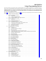
SECTION 4
Using Programming Devices
This section outlines the operations possible with the SYSMAC-CPT, SYSMAC Support Software (SSS) and the Programming Consoles. Actual SYSMAC-CPT operating procedures are provided in the SYSMAC-CPT User Manual. Actual SSS
operating procedures are provided in the SSS Operation Manuals: Basics and C-series PCs. Operations for the
WS02-CXPC1-E CX-Programmer are provided in the WS02-CXPC1-E CX-Programmer User Manual (W361) and
the CX-Server User Manual (W362).
Refer to 3-4-7 Programming Device Connections and 4-3-3 Connecting the Programming Console for details on connecting a
Programming Console or personal computer to the CPM2A.
4-1 SYSMAC-CPT Support Software . . . . . . . . . . . . . . . . . . . . . . . . . . . . . . . . . . . . . . . . . . . .
4-1-1 Introduction . . . . . . . . . . . . . . . . . . . . . . . . . . . . . . . . . . . . . . . . . . . . . . . . . . . . . .
4-1-2 Limitations and Precautions . . . . . . . . . . . . . . . . . . . . . . . . . . . . . . . . . . . . . . . . .
4-1-3 Using the SYSMAC-CPT Support Software . . . . . . . . . . . . . . . . . . . . . . . . . . . . .
4-2 SYSMAC Support Software (SSS) . . . . . . . . . . . . . . . . . . . . . . . . . . . . . . . . . . . . . . . . . . .
4-2-1 Introduction . . . . . . . . . . . . . . . . . . . . . . . . . . . . . . . . . . . . . . . . . . . . . . . . . . . . . .
4-2-2 Limitations and Precautions . . . . . . . . . . . . . . . . . . . . . . . . . . . . . . . . . . . . . . . . .
4-3 Using a Programming Console . . . . . . . . . . . . . . . . . . . . . . . . . . . . . . . . . . . . . . . . . . . . . .
4-3-1 Compatible Programming Consoles . . . . . . . . . . . . . . . . . . . . . . . . . . . . . . . . . . .
4-3-2 Changing the CPM2A’s Mode with the Mode Switch . . . . . . . . . . . . . . . . . . . . . .
4-3-3 Connecting the Programming Console . . . . . . . . . . . . . . . . . . . . . . . . . . . . . . . . .
4-3-4 Preparation for Operation . . . . . . . . . . . . . . . . . . . . . . . . . . . . . . . . . . . . . . . . . . .
4-3-5 Entering the Password . . . . . . . . . . . . . . . . . . . . . . . . . . . . . . . . . . . . . . . . . . . . . .
4-4 Programming Console Operations . . . . . . . . . . . . . . . . . . . . . . . . . . . . . . . . . . . . . . . . . . . .
4-4-1 Overview . . . . . . . . . . . . . . . . . . . . . . . . . . . . . . . . . . . . . . . . . . . . . . . . . . . . . . . .
4-4-2 Clearing Memory . . . . . . . . . . . . . . . . . . . . . . . . . . . . . . . . . . . . . . . . . . . . . . . . . .
4-4-3 Reading/Clearing Error Messages . . . . . . . . . . . . . . . . . . . . . . . . . . . . . . . . . . . . .
4-4-4 Buzzer Operation . . . . . . . . . . . . . . . . . . . . . . . . . . . . . . . . . . . . . . . . . . . . . . . . . .
4-4-5 Assigning Expansion Instruction Function Codes . . . . . . . . . . . . . . . . . . . . . . . . .
4-4-6 Setting and Reading a Program Memory Address and Monitoring I/O Bit Status
4-4-7 Entering or Editing Programs . . . . . . . . . . . . . . . . . . . . . . . . . . . . . . . . . . . . . . . .
4-4-8 Instruction Search . . . . . . . . . . . . . . . . . . . . . . . . . . . . . . . . . . . . . . . . . . . . . . . . .
4-4-9 Bit Operand Search . . . . . . . . . . . . . . . . . . . . . . . . . . . . . . . . . . . . . . . . . . . . . . . .
4-4-10 Inserting and Deleting Instructions . . . . . . . . . . . . . . . . . . . . . . . . . . . . . . . . . . . .
4-4-11 Checking the Program . . . . . . . . . . . . . . . . . . . . . . . . . . . . . . . . . . . . . . . . . . . . . .
4-4-12 Bit, Digit, Word Monitor . . . . . . . . . . . . . . . . . . . . . . . . . . . . . . . . . . . . . . . . . . . .
4-4-13 Differentiation Monitor . . . . . . . . . . . . . . . . . . . . . . . . . . . . . . . . . . . . . . . . . . . . .
4-4-14 Binary Monitor . . . . . . . . . . . . . . . . . . . . . . . . . . . . . . . . . . . . . . . . . . . . . . . . . . .
4-4-15 Three-Word Monitor . . . . . . . . . . . . . . . . . . . . . . . . . . . . . . . . . . . . . . . . . . . . . . .
4-4-16 Signed Decimal Monitor . . . . . . . . . . . . . . . . . . . . . . . . . . . . . . . . . . . . . . . . . . . .
4-4-17 Unsigned Decimal Monitor . . . . . . . . . . . . . . . . . . . . . . . . . . . . . . . . . . . . . . . . . .
4-4-18 Three-Word Data Modification . . . . . . . . . . . . . . . . . . . . . . . . . . . . . . . . . . . . . . .
4-4-19 Changing Timer, Counter SV . . . . . . . . . . . . . . . . . . . . . . . . . . . . . . . . . . . . . . . .
4-4-20 Hexadecimal, BCD Data Modification . . . . . . . . . . . . . . . . . . . . . . . . . . . . . . . . .
4-4-21 Binary Data Modification . . . . . . . . . . . . . . . . . . . . . . . . . . . . . . . . . . . . . . . . . . .
4-4-22 Signed Decimal Data Modification . . . . . . . . . . . . . . . . . . . . . . . . . . . . . . . . . . . .
4-4-23 Unsigned Decimal Data Modification . . . . . . . . . . . . . . . . . . . . . . . . . . . . . . . . . .
4-4-24 Force Set, Reset . . . . . . . . . . . . . . . . . . . . . . . . . . . . . . . . . . . . . . . . . . . . . . . . . . .
4-4-25 Clear Force Set/Reset . . . . . . . . . . . . . . . . . . . . . . . . . . . . . . . . . . . . . . . . . . . . . . .
4-4-26 Hex-ASCII Display Change . . . . . . . . . . . . . . . . . . . . . . . . . . . . . . . . . . . . . . . . .
4-4-27 Displaying the Cycle Time . . . . . . . . . . . . . . . . . . . . . . . . . . . . . . . . . . . . . . . . . .
4-4-28 Reading and Setting the Clock . . . . . . . . . . . . . . . . . . . . . . . . . . . . . . . . . . . . . . . .
4-5 Programming Example . . . . . . . . . . . . . . . . . . . . . . . . . . . . . . . . . . . . . . . . . . . . . . . . . . . . .
4-5-1 Preparatory Operations . . . . . . . . . . . . . . . . . . . . . . . . . . . . . . . . . . . . . . . . . . . . .
4-5-2 Example Program . . . . . . . . . . . . . . . . . . . . . . . . . . . . . . . . . . . . . . . . . . . . . . . . .
4-5-3 Programming Procedures . . . . . . . . . . . . . . . . . . . . . . . . . . . . . . . . . . . . . . . . . . . .
4-5-4 Checking the Program . . . . . . . . . . . . . . . . . . . . . . . . . . . . . . . . . . . . . . . . . . . . . .
4-5-5 Test Run in MONITOR Mode . . . . . . . . . . . . . . . . . . . . . . . . . . . . . . . . . . . . . . . .
83
Section
SYSMAC-CPT Support Software
4-1
4-1
SYSMAC-CPT Support Software
4-1-1 Introduction
The SYSMAC-CPT Support Software is a complete programming and control
package. It provides not only programming capabilities, but also advanced
debugging, monitoring, and program/data management. The software is compatible with Windows 3.1, Windows 95, Windows 98, and Windows NT 3.5/4.0.
Any version of the SYSMAC-CPT Support Software can be used to program
CPM2A PCs with the limitations described later in this section. For further
information and actual operating procedures, please refer to the SYSMAC-CPT
Support Software Quick Start Guide (W332) and User Manual (W333).
Refer to 3-4-7 Programming Device Connections for details on connecting a
personal computer to the CPM2A.
4-1-2 Limitations and Precautions
When programming a CPM2A PC with the SYSMAC-CPT Support Software, set
the PC model to “CQM1” and the CPU model to “CPU43.” There are some software limitations because of differences between the CPM2A and CQM1-CPU43
CPUs.
Program Input and
Program Check
CQM1 data areas are larger than the corresponding CPM2A data areas, so the
data area addresses that don’t actually exist in the CPM2A or instructions not
supported by the CPM2A can be input and won’t be detected in the program
check. Be sure that the word and bit addresses are within the specified ranges
and that all instructions are supported.
If a program contains a data area address that exceeds the range of a CPM2A
data area, a memory error will be generated when the program is executed and
the Memory Area Specification Error Flag (AR 1308) will be turned ON.
Data area
CQM1 range
CPM2A range
Input words
IR 000 to IR 011
IR 000 to IR 009
Output words
IR 100 to IR 111
IR 010 to IR 019
Work words and
dedicated words
IR 012 to IR 099
IR 020 to IR 049/IR 200 to IR 227
(IR 050 to IR 199 cannot be used.)
SR area
SR 244 to SR 255
SR 228 to SR 255
HR area
HR 00 to HR 99
HR 00 to HR 19
(HR 20 to HR 99 cannot be used.)
AR area
AR 00 to AR 27
AR 00 to AR 23
(AR 24 to AR 27 cannot be used.)
LR area
LR 00 to LR 63
LR 00 to LR 15
(LR 16 to LR 63 cannot be used.)
Timer/Counter
area
TIM/CNT 000 to 511
TIM/CNT 000 to 255
(TIM/CNT 256 to 511 cannot be used.)
DM
area
Read/write DM 0000 to DM 6143 DM 0000 to DM 1999,
DM 2022 to DM 2047
(DM 2048 to DM 6143 cannot be used.)
Read-only
Error Log
PC Setup
DM 6144 to DM 6568 DM 6144 to DM 6599
DM 6569 to DM 6599 DM 2000 to DM 2021
DM 6600 to DM 6655 DM 6600 to DM 6655
Monitoring, Online
Editing, and Set Values
An error message will be displayed and the values will not be accepted if a data
area address that exceeds the range of a CPM2A data area is entered for monitoring, an instruction operand, or a timer/counter SV.
Available Program
Memory
The program capacity of the CQM1 (7,200 words) is greater than that of the
CPM2A (4,096 words), and so the display will show more free space than is actually available. Be sure to keep the actual program capacity in mind while programming.
84
Section
SYSMAC-CPT Support Software
4-1
Program Transfer
When the program is transferred from the PC to the CPT with the default function
code assignments, FUN18, FUN19, FUN87, and FUN88 will be displayed as
TKY, MCMP, DSW, and 7SEG. The instructions, however, will be transferred
correctly.
An error will occur if any instructions not supported by the CPT are transferred
from the CPM2A.
When the program is transferred from the CPT to the PC, TKY, MCMP, DSW,
and 7SEG will be displayed on the CPT, but will not be executed in the CPU Unit.
They will be treated as NOP.
If expansion instructions are transferred to the PC with DM 6602 is set to the “default settings” or if instructions not supported by the CPM2A are transferred to
the PC, a message saying that expansion instructions cannot be written because DIP switch pin 4 is OFF will be displayed. Change the setting of DM 6602
to enable user settings to use expansion instructions.
Expansion Instructions
It will not be possible to transfer the program if the function codes assigned to
expansion instructions (18 instructions) have been changed from their default
settings. A message to turn ON the DIP switch of the PC and execute again will
be displayed. Change the function code assignments to the CQM1 defaults
shown in the following table before programming.
Function code
Default CPM2A Assignments
17
ASFT
ASFT
Default CQM1 Assignments
18
---
TKY
19
---
MCMP
47
RXD
RXD
48
TXD
TXD
60
CMPL
CMPL
61
INI
INI
62
PRV
PRV
63
CTBL
CTBL
64
SPED
SPED
65
PULS
PULS
66
SCL
SCL
67
BCNT
BCNT
68
BCMP
BCMP
69
STIM
STIM
87
---
DSW
88
---
7SEG
89
INT
INT
There are four CPM2A instructions (STUP(––), SYNC(––), TIML(––), and
TMHH(––)) that are not supported by the CQM1 and cannot be used. If one of
these instructions is used in the program, an error will occur when the program is
transferred from the PC to the computer.
The input word for the frequency for PWM must be between IR 000 and IR 049,
or between IR 200 and IR 252.
If a CQM1 instruction that is not supported by the CPM2A is used in the program,
an error will occur when the program is transferred from the computer to the PC.
Error Log
The error log cannot be displayed. If data has been written to DM 6569 to
DM 6599, however, this data will be incorrectly displayed as the error log. Do not
use the information that is displayed.
PC Setup
Some of the CPM2A’s PC Setup settings are different from those in the CQM1,
so not all settings can be made from the menus. These settings have to be made
by writing data directly to the word containing the setting.
85
SYSMAC-CPT Support Software
Section
4-1
4-1-3 Using the SYSMAC-CPT Support Software
This section shows how to perform basic SYSMAC-CPT Support Software operations with the CPM2A PC. (The software is operating in a Windows 95 environment in these examples.)
Starting the Software
The SYSMAC-CPT Support Software is a Windows 3.1/Windows 95 application. Refer to the SYSMAC-CPT Support Software User Manual (W333) for details on computer requirements and the software installation procedure.
1, 2, 3...
1. Select “Programs (P)” from the Start Menu, “SYSMAC-CPT,” and then
“SYSMAC-CPT” to start the software.
2. Read the notes provided in the startup messages and click “OK.”
3. The SYSMAC-CPT Support Software will start.
Note To exit from the SYSMAC-CPT Support Software, select “File (F)” from the menu
bar and “Exit (X)” from the File menu.
86
Section
SYSMAC-CPT Support Software
Creating a New Project
1, 2, 3...
4-1
Follow this procedure when using SYSMAC-CPT Support Software for the first
time or creating a new project. Specify the PC model and CPU version of the PC
being used.
1. Select “File (F)” from the menu bar and “New (N)” from the File menu.
2. Input the name of the new project, set the PC model to “CQM1,” set the CPU
version to “CPU43,” and click “OK.”
d) Click OK.
a) Input the
project name.
b) Set the PC model to CQM1.
c) Set the PC model to CQM1.
3. The new project’s ladder diagram will be displayed.
87
Section
SYSMAC-CPT Support Software
Writing and Editing the
Ladder Program
The SYSMAC-CPT Support Software can display programs in ladder-diagram
format or mnemonic format. To switch the display/editing format, select
“View (V)” from the menu bar, “Program editor (P),” and then “Ladder (L)” or
“Mnemonic (M).”
Ladder-diagram format
Transferring the Program
88
4-1
Mnemonic format
There are three steps involved in transferring the program.
• Connect the CPM2A with the computer in which the SYSMAC-CPT Support
Software has been installed.
• Switch the SYSMAC-CPT Support Software to online operation.
• Transfer the program.
Section
SYSMAC-CPT Support Software
4-1
Connecting the CPM2A with the Computer
Securely insert the computer Connecting Cable to the CPM2A’s peripheral port
and then turn on the CPM2A’s power supply.
IBM PC/AT or compatible
personal computer
CPM2A CPU Unit
Connecting Cable
S CQM1-CIF01
(25-pin D-Sub Connector)
S CQM1-CIF02
(9-pin D-Sub Connector)
Operating Modes
If power is turned ON to the CPM2A without anything connected to the peripheral port, the CPM2A will start operation in RUN mode. If operation starts in RUN
mode when power is turned ON even though a Connecting Cable is correctly
connected to the peripheral port, check the settings in the PC Setup in the
CPM2A.
The CMP2A has three operating modes: PROGRAM, MONITOR, and RUN.
When the CPT is offline, the CPM2A will operate in PROGRAM mode. When the
CPT is online, the CPM2A operating mode can be controlled from the CPT.
PROGRAM Mode
The CPM2A program isn’t executed in PROGRAM mode. Use PROGRAM
mode to create and edit the program, clear memory, or check the program for
errors.
MONITOR Mode
The CPM2A program is executed in MONITOR mode and I/O is processed just
as it is in RUN mode. Use MONITOR mode to test system operations, such as
monitoring CPM2A operating status, force-setting and resetting I/O bits, changing the SV/PV of timers and counters, changing word data, and online editing.
RUN Mode
This is the CPM2A’s normal operating mode. The CPM2A’s operating status can
be monitored from a Programming Device, but bits can’t be force-set/force-reset
and the SV/PV of timers and counters can’t be changed.
89
Section
SYSMAC-CPT Support Software
4-1
Switching to Online Operation
The SYSMAC-CPT Support Software must make an online connection in order
to communicate with the CPM2A, transfer the program, or change the CPM2A’s
operating mode.
1, 2, 3...
1. Select “Online (O)” from the menu bar and “Go online (G)” from the Online
menu.
2. A confirmation message will be displayed. Click “OK” to go online.
Cancel
3. The ladder-diagram display will change to indicate the online connection.
Changes to “Program,” showing
the PC’s operating mode.
90
Section
SYSMAC-CPT Support Software
4-1
Transferring the Program
Use the following procedure to transfer a program to the PC.
Before attempting to transfer the program, make sure that the SYSMAC-CPT
Support Software is online and that the CPM2A is in PROGRAM mode. The program cannot be transferred unless the PC is in PROGRAM mode.
1, 2, 3...
1. Check that the PC is in PROGRAM mode, select “Online (O)” from the menu
bar, and “Transfer (Computer → PC (T))” from the Online menu.
Make sure that the CPM2A is in PROGRAM mode
before attempting to transfer the program.
2. Select “Program” and click “Transfer (Computer → PC)” to begin transfer
the program.
b) Click to begin
the program
transfer.
a) Select “Program.”
Checking Operation in MONITOR Mode
Use the following procedure to switch the CPM2A to MONITOR mode.
1, 2, 3...
1. Make sure that the SYSMAC-CPT Support Software is online. Select “Online (O)” from the menu bar, select “Mode (M),” and then “MONITOR (M).”
2. A confirmation message will be displayed. Click “OK” to switch to MONITOR
mode.
Cancel
91
Section
SYSMAC Support Software (SSS)
4-2
Starting Operation in RUN Mode
Use the following procedure to switch the CPM2A to RUN mode.
1, 2, 3...
1. Make sure that the SYSMAC-CPT Support Software is online. Select “Online (O)” from the menu bar, select “Mode (M),” and then “RUN (R).”
2. A confirmation message will be displayed. Click “OK” to switch to RUN
mode.
Cancel
4-2
SYSMAC Support Software (SSS)
4-2-1 Introduction
The SSS is a complete programming and control package designed for C-series
and CVM1 PCs. It provides not only programming capabilities, but also
advanced debugging, monitoring, and program/data management. For further
information and actual operating procedures, please refer to the SYSMAC Support Software Operation Manuals: Basics and C-series.
CPM2A programming can be performed with any version of the SSS.
Refer to 3-4-7 Programming Device Connections for details on connecting a
personal computer to the CPM2A.
4-2-2 Limitations and Precautions
When programming a CPM2A PC with the SSS, set the PC model to “CQM1.”
There are some software limitations because of differences between the
CPM2A and CQM1 CPUs.
CQM1
A:
K:
Program Input and
Program Check
92
CVM1-CPU21
CQM1
CQM1 data areas are larger than the corresponding CPM2A data areas, so the
data area addresses that don’t actually exist in the CPM2A or instructions not
supported by the CPM2A can be input and won’t be detected in the program
check. Be sure that the word and bit addresses are within the specified ranges
and that all instructions are supported.
Section
SYSMAC Support Software (SSS)
4-2
If a program contains a data area address that exceeds the range of a CPM2A
data area, a memory error will be generated when the program is executed and
the Memory Area Specification Error Flag (AR 1308) will be turned ON.
Data area
CQM1 range
CPM2A range
Input words
IR 000 to IR 011
IR 000 to IR 009
Output words
IR 100 to IR 111
IR 010 to IR 019
Work words
IR 012 to IR 099
IR 020 to IR 049/IR 200 to IR 227
(IR 050 to IR 199 cannot be used.)
SR area
SR 244 to SR 255
SR 228 to SR 255
HR area
HR 00 to HR 99
HR 00 to HR 19
(HR 20 to HR 99 cannot be used.)
AR area
AR 00 to AR 27
AR 00 to AR 23
(AR 24 to AR 27 cannot be used.)
LR area
LR 00 to LR 63
LR 00 to LR 15
(LR 16 to LR 63 cannot be used.)
Timer/Counter
area
TIM/CNT 000 to 511
TIM/CNT 000 to 255
(TIM/CNT 256 to 511 cannot be used.)
DM
area
Read/write DM 0000 to DM 6143 DM 0000 to DM 1999,
DM 2022 to DM 2047
(DM 2048 to DM 6143 cannot be used.)
Read-only
Error Log
PC Setup
DM 6144 to DM 6568 DM 6144 to DM 6599
DM 6569 to DM 6599 DM 2000 to DM 2021
DM 6600 to DM 6655 DM 6600 to DM 6655
Monitoring, Online
Editing, and Set Values
An error message will be displayed and the values will not be accepted if a data
area address that exceeds the range of a CPM2A data area is entered for monitoring, time charts, an instruction operand, or a timer/counter SV.
Transferring and
Verifying DM Area Data
DM Area addresses not supported by the CPM2A cannot be transferred or monitored. DM 1024 to DM 6143 are not checked for DM Area verification.
Available Program
Memory
Since the program capacity of the CQM1 (7,200 words) is greater than that of the
CPM2A (4,096 words), the display will show more free space than is actually
available. Be sure to keep the actual program capacity in mind while programming.
Program Transfer
When the program is transferred from the PC to the SSS with the default function
code assignments, FUN18, FUN19, FUN87, and FUN88 will be displayed as
TKY, MCMP, DSW, and 7SEG. The instructions, however, will be transferred
correctly.
“???” will be displayed if any instructions not supported by the SSS are transferred from the CPM2A. Mnemonics will be displayed, however, if any have been
defined for the specified function code.
When the program is transferred from the SSS to the PC, TKY, MCMP, DSW,
and 7SEG will be displayed on the SSS, but will not be executed in the CPU Unit.
They will be treated as NOP.
If expansion instructions are transferred to the PC with DM 6602 is set to the “default settings,” a message saying that expansion instructions cannot be written
because DIP switch pin 4 is OFF will be displayed. Change the setting of
DM 6602 to enable user settings to use expansion instructions. If instructions
not supported by the CPM2A are transferred to the PC, a message saying to set
expansion instructions will be displayed, and transfer will not be possible.
93
Section
SYSMAC Support Software (SSS)
Expansion Instructions
4-2
It will not be possible to transfer the program if the function codes assigned to
expansion instructions have been changed from their default settings. A message to turn ON the DIP switch of the PC and execute again will be displayed.
Change the function code assignments to the CQM1 defaults shown in the following table before programming.
Function code
Default CPM2A Assignments
17
ASFT
ASFT
Default CQM1 Assignments
18
---
TKY
19
---
MCMP
47
RXD
RXD
48
TXD
TXD
60
CMPL
CMPL
61
INI
INI
62
PRV
PRV
63
CTBL
CTBL
64
SPED
SPED
65
PULS
PULS
66
SCL
SCL
67
BCNT
BCNT
68
BCMP
BCMP
69
STIM
STIM
87
---
DSW
88
---
7SEG
89
INT
INT
If a CQM1 instruction that is not supported by the CPM2A is used in the program,
an error will occur when the program is transferred from the computer to the PC.
There are four CPM2A instructions (STUP(––), SYNC(––), TIML(––), and
TMHH(––)) that are not supported by the CQM1. These instructions can be used
by transferring the expansion instructions from the CPM2A to the SSS. This procedure is outlined below.
1, 2, 3...
1. Select “Transfer Instr” from the “Utility” menu.
2. Confirm the transfer by pressing “Y” when the confirmation pop-up is displayed.
3. The “Utility” menu will be displayed again when the transfer is completed.
PC Setup
94
Since some of the CPM2A’s PC Setup settings are different from those in the
CQM1, not all settings can be made from the menus. These settings have to be
made by writing data directly to the word containing the setting.
Section
Using a Programming Console
4-3
4-3
Using a Programming Console
This section provides information on connecting and using a Programming Console. Refer to 5-3 Programming Console Operation Errors for details on errors
that might occur during Programming Console operations.
4-3-1 Compatible Programming Consoles
There are two Programming Consoles that can be used with the CPM2A: The
CQM1-PRO01-E and the C200H-PRO27-E. The key functions for these Programming Consoles are identical.
Press and hold the Shift Key to input a letter shown in the upper-left corner of the
key or the upper function of a key that has two functions. For example, the
CQM1-PRO01-E’s AR/HR Key can specify either the AR or HR Area; press and
release the Shift Key and then press the AR/HR Key to specify the AR Area.
CQM1-PRO01-E
LCD display
Attached Connecting
Cable (2 m)
Mode switch
Operation keys
C200H-PRO27-E
LCD display
Mode switch
Operation keys
Cassette recorded jack
(Cannot be used with the CPM2A).
Connecting Cables
C200H-CN222 (2 m)
C200H-CN422 (4 m)
95
Section
Using a Programming Console
Different Keys
4-3
The following keys are labeled differently on the CQM1-PRO01-E and the
C200H-PRO27-E, but the operation of the keys in each pair is identical.
CQM1-PRO01-E Keys
C200H-PRO27-E Keys
AR
HR
HR
PLAY
SET
SET
REC
RESET
RESET
Note To specify the AR area, use SHIFT and HR Keys for the C200H-PRO27-E and
use SHIFT and AR/HR Keys for the CQM1-PRO01-E.
A shift symbol will be displayed in the upper-right corner of the screen when the
Shift Key is pressed. The shift input can be cleared by pressing the Shift Key
again.
^
SHIFT
Shift input
symbol
Mode Switch
The mode switch controls the CPM2A’s operating mode. The key can be removed when the switch is set to RUN or MONITOR but it cannot be removed
when the switch is set to PROGRAM.
Contrast Control
The display contrast can be adjusted with the control on the right side of the Programming Console.
Contrast control
Buzzer Volume
The C200H-PRO27-E’s buzzer volume can be adjusted with the lever on the
right side of the Programming Console. The CQM1-PRO01-E’s buzzer volume
cannot be adjusted.
Low volume
High volume
C200H-PRO27-E
Note The buzzer volume can be turned on and off with a key operation. See 4-4-4
Buzzer Operation for details.
96
Section
Using a Programming Console
4-3
4-3-2 Changing the CPM2A’s Mode with the Mode Switch
Once the Programming Console has been connected, its mode switch can be
used to change the CPM2A’s operating mode. The mode display (<PROGRAM>, <MONITOR>, or <RUN>) will appear on the Programming Console
screen.
• No key operations can be performed while the mode display is displayed on
the Programming Console screen. Press CLR to clear the display so that key
operations can be performed.
• If the SHIFT Key is pressed while the mode switch is turned, the original display will remain on the Programming Console’s screen and the mode display
won’t appear.
• The CPM2A will enter RUN mode automatically if a Programming Console
isn’t connected when the CPM2A is turned on.
MONITOR
RUN
PROGRAM
MONITOR
RUN
PROGRAM
MONITOR
RUN
PROGRAM
Mode display
<PROGRAM>
BZ
Operation
<MONITOR>
CLR
Initial display
BZ
Operation
<RUN>
SHIFT
BZ
CLR
00000
Operating Modes
PROGRAM Mode
The CPM2A program isn’t executed in PROGRAM mode. Use PROGRAM
mode to create and edit the program, clear memory, or check the program for
errors.
MONITOR Mode
The CPM2A program is executed in MONITOR mode and I/O is processed just
as it is in RUN mode. Use MONITOR mode to test system operations, such as
monitoring CPM2A operating status, force-setting and resetting I/O bits, changing the SV/PV of timers and counters, changing word data, and online editing.
RUN Mode
This is the CPM2A’s normal operating mode. The CPM2A’s operating status can
be monitored from a Programming Device, but bits can’t be force-set/force-reset
and the SV/PV of timers and counters can’t be changed.
! Caution
Check the system thoroughly before changing the operating mode of the PC to
prevent any accidents that might occur when the program is first started.
! Caution
Never change the mode while pressing any of the keys.
97
Section
Using a Programming Console
Startup Operating Mode
4-3
The operating mode of the CPM2A when the power is turned ON depends upon
the PC Setup setting in DM 6600 and the Programming Console’s mode switch
setting if the Programming Console is connected.
PC Setup setting
(DM 6600)
0000
0100
Programming
Console connected
Programming Console not
connected
The startup mode
determined by the
mode switch setting.
RUN mode if no Programming Device
is connected. PROGRAM mode if
another Programming Device is
connected.
The startup mode is the same as the operating mode before
power was interrupted.
0200
PROGRAM mode
0201
MONITOR mode
0202
RUN mode
Note The default setting is 0000. If a Programming Console is not connected, the PC
will automatically enter RUN mode. Be sure that it is safe for the PC to operate
before turning on the PC without a Programming Console connected.
4-3-3 Connecting the Programming Console
Connect the Programming Console’s connecting cable to the CPM2A’s peripheral port, as shown below.
Panel Installation
The C200H-PRO27-E Programming Console can be installed in a control panel
as shown in the following diagram. (The C200H-ATT01 Mounting Bracket is sold
separately.)
Mounting Bracket
Mounting hole dimensions
(DIN43700 standards)
Two screws
+1.1
186 –0
Panel thickness: 1.0 to 3.2 mm
98
92 +0.8
–0
Section
Using a Programming Console
4-3
Allow at least 80 mm for the cable connector above the Programming Console.
37
15
At least 80 mm is required.
Either connector may
be used.
About 70 mm is required.
4-3-4 Preparation for Operation
This section describes the procedures required to begin Programming Console
operation when using the Programming Console for the first time.
! Caution
Always confirm that the Programming Console is in PROGRAM mode when
turning ON the PC with a Programming Console connected unless another
mode is desired for a specific purpose. If the Programming Console is in RUN
mode when PC power is turned ON, any program in Program Memory will be
executed, possibly causing a PC-controlled system to begin operation.
The following sequence of operations must be performed before beginning initial program input.
1, 2, 3...
1. Be sure that the PC is OFF.
2. Connect the Programming Console to the CPU Unit’s peripheral port. See
4-3-3 Connecting the Programming Console for details.
(The CPU Unit’s Communications Switch setting has no effect on communications with the Programming Console.)
3. Set the mode switch to PROGRAM mode.
4. Turn ON the PC.
5. Enter the password. See 4-3-5 Entering the Password for details.
6. Clear (All Clear) the PC’s memory. See 4-4-2 Clearing Memory for details.
7. Read and clear all errors and messages. See 4-4-3 Reading/Clearing Error
Messages for details.
8. Start programming.
4-3-5 Entering the Password
To gain access to the PC’s programming functions, you must first enter the password. The password prevents unauthorized access to the program.
The PC prompts you for a password when PC power is turned on or, if PC power
is already on, after the Programming Console has been connected to the PC. To
gain access to the system when the “Password!” message appears, press CLR
and then MONTR. Then press CLR to clear the display.
99
Section
Using a Programming Console
4-3
If the Programming Console is connected to the PC when PC power is already
on, the first display below will indicate the mode the PC was in before the Programming Console was connected. Ensure that the PC is in PROGRAM mode
before you enter the password. When the password is entered, the PC will
shift to the mode set on the mode switch, causing PC operation to begin if the
mode is set to RUN or MONITOR. The mode can be changed to RUN or MONITOR with the mode switch after entering the password.
<PROGRAM>
PASSWORD!
<PROGRAM>
BZ
Indicates the mode set by the mode selector switch.
100
Section
Programming Console Operations
4-4
4-4
Programming Console Operations
4-4-1 Overview
The following table lists the programming and monitoring operations that can be
performed from a Programming Console. Refer to the rest of this section for
details on operational procedures.
Name
Function
Page
Clearing memory
Clears all or part of the Program Memory and any data areas that are not
read-only, as well as the contents of the Programming Console’s memory.
102
Reading/clearing error
messages
Displays and clears error messages and displays MESSAGE instruction
messages.
103
Buzzer operation
Turns on and off the buzzer that sounds when Programming Console keys
are pressed.
103
Assigning expansion
instruction function codes
Reads or changes the function codes assigned to expansion instructions
104
Setting a program memory
address
Sets the specified program memory address when reading, writing,
inserting and deleting programs.
105
Reading a program memory
address
Reads the contents of the Program Memory. Displays the status of the
currently displayed bit in PROGRAM and MONITOR modes.
105
Instruction search
Finds occurrences of the specified instruction in the program.
108
Bit operand search
Finds occurrences of the specified operand bit in the program.
109
Inserting and deleting
instructions
Inserts or deletes instructions from the program.
110
Entering or editing programs
Overwrites the contents of the current Program Memory to either input a
program for the first time or to change a program that already exists.
105
Checking the program
Checks for programming errors and displays the program address and
error when errors are found.
111
Bit, digit, word monitor
Monitors the status of up to 16 bits and words, although only 3 can be
shown on the display at one time.
111
Multiple address monitor
Monitors the status of up to 6 bits and words simultaneously.
113
Differentiation monitor
Monitors the up or down differentiation status of a particular bit.
113
Binary monitor
Monitors the ON/OFF status of any word’s 16 bits.
114
3-word monitor
Monitors the status of three consecutive words.
115
Signed decimal monitor
Converts the contents of the specified word from signed hexadecimal
(two’s complement format) to signed decimal for display.
115
Unsigned decimal monitor
Converts hexadecimal data in a word to unsigned decimal for display.
116
3-word data modification
Changes the contents of one or more of the 3 consecutive words
displayed in the 3-Word Monitor operation.
116
Changing timer, counter SV 1
Changes the SV of a timer or counter.
117
Changing timer, counter SV 2
Makes fine adjustment changes to the SV of the timer or counter.
118
Hexadecimal, BCD data
modification
Changes the BCD or hexadecimal value of a word being monitored.
118
Binary data modification
Changes the status of a word’s bits when the word is being monitored.
119
Signed decimal data
modification
Changes the decimal value of a word being monitored as signed decimal
data, within a range of –32,768 to 32,767. The contents of the specified
word are converted automatically to signed hexadecimal (two’s
complement format.)
Changes the decimal value of a word being monitored as unsigned
decimal data, within a range of 0 to 65,535. A change into hexadecimal
data is made automatically.
119
Force set/reset
Forces bits ON (force set) or OFF (force reset.)
121
Clear force set/reset
Restores the status of all bits which have been force set of reset.
122
Hex-ASCII display change
Converts word data displays back and forth between 4-digit hexadecimal
data and ASCII.
122
Unsigned decimal data
modification
120
101
Section
Programming Console Operations
Name
Function
4-4
Page
Displaying the cycle time
Displays the current average cycle time (scan time.)
123
Reading and setting the clock
Reads or sets the internal clock.
123
4-4-2 Clearing Memory
This operation is used to clear all or part of the Program Memory and data areas,
as well as the contents of the Programming Console’s memory. This operation is
possible in PROGRAM mode only.
RUN
MONITOR
No
No
PROGRAM
OK
Before beginning to program for the first time or when installing a new program,
clear all areas.
All Clear
The following procedure is used to clear memory completely, including the program, all data areas, counter PVs, Data Memory, and the PC Setup (DM 6600 to
DM 6655).
1, 2, 3...
1. Bring up the initial display by pressing the CLR Key repeatedly.
2. Press the SET, NOT, and then the RESET Key to begin the operation.
SET
NOT
RESET
00000MEMORY CLR?
HR
CNT DM
3. Press the MONTR Key to clear memory completely.
MONTR
! Caution
Partial Clear
00000MEMORY CLR
END HR
CNT DM
The PC Setup (DM 6600 through DM 6655) will be cleared when this operation is
performed.
It is possible to retain the data in specified areas or part of the Program Memory.
To retain the data in the HR, TC, or DM Areas, press the appropriate key after
pressing SET, NOT, and RESET. Any data area that still appears on the display
will be cleared when the MONTR Key is pressed.
The HR Key is used to specify both the AR and HR Areas, the CNT Key is used to
specify the entire timer/counter area, and the DM Key is used to specify the DM
Area.
It is also possible to retain a portion of the Program Memory from the first
memory address to a specified address. After designating the data areas to
be retained, specify the first Program Memory address to be cleared. For
example, input 030 to leave addresses 000 to 029 untouched, but to clear
addresses from 030 to the end of Program Memory.
As an example, follow the procedure below to retain the timer/counter area and
Program Memory addresses 000 through 122:
1, 2, 3...
1. Press the CLR Key to bring up the initial display.
2. Press the SET, NOT, and then the RESET Key to begin the operation.
3. Press the CNT Key to remove the timer/counter area from the data areas
shown on the display. (Counter PVs will not be cleared.)
CNT
00000MEMORY CLR?
HR
DM
4. Press 123 to specify 123 as the starting program address.
B
102
1
C
2
D
3
00123MEMORY CLR?
HR
DM
Section
Programming Console Operations
4-4
5. Press the MONTR Key to clear the specified regions of memory.
MONTR
00000MEMORY CLR
END HR
DM
4-4-3 Reading/Clearing Error Messages
This operation is used to display and clear error messages. It is possible to display and clear non-fatal errors and MESSAGE instruction messages in any
mode, but fatal errors can be cleared in PROGRAM mode only.
RUN
MONITOR
OK
OK
PROGRAM
OK
Before inputting a new program, any error messages recorded in memory
should be cleared. It is assumed here that the causes of any of the errors for
which error messages appear have already been taken care of. If the buzzer
sounds when an attempt is made to clear an error message, eliminate the
cause of the error, and then clear the error message. (Refer to Section 5 Test
Runs and Error Processing for troubleshooting information.)
Key Sequence
Follow the procedure below to display and clear messages.
1, 2, 3...
1. Press the CLR Key to bring up the initial display.
2. Press the FUN and then the MONTR Key to begin the operation. If there are
no messages, the following display will appear:
FUN
MONTR
ERR/MSG CHK OK
If there are messages, the most serious message will be displayed when the
MONTR Key is pressed. Pressing MONTR again will clear the present message and display the next most serious error message. Continue pressing
MONTR until all messages have been cleared. These are some examples
of error messages:
A memory error:
MONTR
MEMORY ERR
A system error:
MONTR
SYS FAIL FAL01
A message (displayed with MSG(46)):
MONTR
MATERIAL USED UP
All messages cleared:
MONTR
ERR/MSG CHK OK
4-4-4 Buzzer Operation
This operation is used to turn on and off the buzzer that sounds when Programming Console keys are pressed. This buzzer will also sound whenever an error
occurs during PC operation. Buzzer operation for errors is not affected by this
setting.
This operation is possible in any mode.
RUN
OK
MONITOR
OK
PROGRAM
OK
103
Section
Programming Console Operations
Key Sequence
4-4
Follow the procedure below to turn the key-input buzzer on and off.
1, 2, 3...
1. Press the CLR, SHIFT, and then the CLR Key to bring up the mode display.
In this case the PC is in PROGRAM mode and the buzzer is ON.
CLR
SHIFT
CLR
<MONITOR>
BZ
2. Press the SHIFT and then the 1 Key to turn off the buzzer.
SHIFT
B
1
<MONITOR>
The buzzer will not sound
when “BZ” is not displayed.
3. Press the SHIFT and then the 1 Key again to turn the buzzer back ON.
SHIFT
B
1
<MONITOR>
BZ
4-4-5 Assigning Expansion Instruction Function Codes
This operation is used to display or change the expansion instructions assigned
to expansion instruction function codes. The assignments can be displayed in
any mode, but can be changed in PROGRAM mode only.
Operation
RUN
MONITOR
PROGRAM
Read assignment
OK
OK
OK
Change assignment
No
No
OK
Assign expansion instruction function codes before inputting the program.
The CPM2A will not operate properly if expansion instructions aren’t assigned correctly. An expansion instruction can be assigned to one function
code only.
The PC Setup must be set for user-defined expansion instruction assignments. Set bits 8 to 11 of DM 6602 to 1 and turn the PC’s power off and then
on again to enable the new setting.
There is a table on page 85 showing the default function code assignments
in the CPM2A.
1, 2, 3...
1. Press the CLR Key to bring up the initial display.
2. Press the EXT Key to display the assignment for the first function code (17).
EXT
INST TBL
READ
FUN017:ASFT
3. Press the Up and Down Arrow Keys to scroll through the expansion instruction function codes.
↓
INST TBL
READ
FUN018:FUN
4. Press the CHG Key to assign a different expansion instruction to the selected function code.
CHG
INST TBL
CHG?
FUN018:FUN ~????
5. Press the Up and Down Arrow Keys to scroll through the expansion instructions that can be assigned to the selected function code.
↓
104
INST TBL
CHG?
FUN018:FUN ~HEX