1
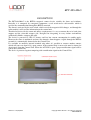
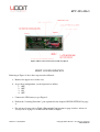
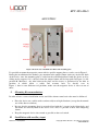
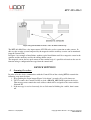
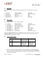
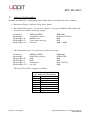
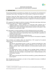
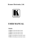
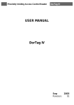
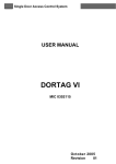
RFT-868-MAG
WIRELESS NETWORK
USER MANUAL
868.3 MHz
RFT-868-MAG
Wireless Magnetic Sensor
Release A - 01/09/2015
Copyright 2015 Udoit Srl - All rights are reserved
www.udoit.eu
RFT-868-MAG
Device Specifications
Power Supply: 3V (1xCR2 battery)
Current Draw in standby mode: 5.5µA
Temperature Working Range: -10 ÷ +55°C
Dimensions ( L x W x H ): 38 x 24 x 98 mm (device), 19 x 14 x 46 mm (magnetic)
Radio Module TRX Features1
Low Rx power consumption: 10mA.
Low Tx power consumption: 33mA @+10dBm.
Low Standby consumption: 4 µA.
Radio Operative Frequency: 868.3 MHz.
FSK Modulation.
Good reception sensitivity: down to -100 dBm at 25 kb/s in FSK.
Transmit power: 7 dBm
Packet handling feature with data whitening and automatic CRC generation.
Incoming sync word recognition.
Distance coverage: up to 20 m indoors (depending on building materials).
Effective Radiated Power (ERP): 5mW.
RFTide Network Features
Wireless mesh network topology.
Proprietary routing protocol and software application.
Centrally managed network from a Control Unit.
Advanced Encryption Standard (AES) of the data.
Typical Applications
Wireless alarm and security systems.
Wireless sensor networks.
Automated Meter reading.
Home and building automation.
Industrial monitoring and control.
Remote wireless control.
Revision History
Date
15/09/2015
Version
1.0
Revision
Initial Release
1
Refer to RFTide Transceiver for mesh network datasheet
http://www.aurelwireless.com/wp-content/uploads/2015/04/650201380G_sf.pdf
Release A - 01/09/2015
Copyright 2015 Udoit Srl - All rights are reserved
www.udoit.eu
RFT-868-MAG
CAUTION
Read this manual before attempting to install the device!
Failure to observe recommendations included in this manual may
be dangerous or cause a violation of the law. The manufacturer
Udoit Srl will not be held responsible for any loss or damage
resulting from not following the instruction of operating manual.
When handled carelessly or used in non-specified environment
conditions, the device may not function properly. It’s highly
recommended to ensure safety and property protection.
The RFT-868-MAG is a battery-powered device. Using batteries
other than specified may result in explosion. Dispose of properly,
observing environmental protection rules.
Release A - 01/09/2015
Copyright 2015 Udoit Srl - All rights are reserved
www.udoit.eu
RFT-868-MAG
DESCRIPTION ....................................................................................................................5
FIRST CONFIGURATION ...................................................................................................6
MOUNTING .........................................................................................................................7
DEVICE SETTINGS.............................................................................................................8
MAINTENANCE.................................................................................................................12
Release A - 01/09/2015
Copyright 2015 Udoit Srl - All rights are reserved
www.udoit.eu
RFT-868-MAG
DESCRIPTION
The RFT-868-MAG is the RFTide magnetic contact device suitable for doors and windows.
Basically, it is composed by a magnetic component, a reed switch and a radio module which is
used for the communication through the RFTide network.
The alarm is activated by the reed switch, which reveals the magnetic field changes, and through the
radio module it will send the information to the control unit.
That kind of device fits the room and offices requirements, it’s easy to mount due to its back plate
support and the selectable magnet side. Designed for integrating in every indoor environment,
aesthetically likable, compact and solid.
The device is powered by CR2 3V battery and has low current consumption in standby mode.
However the status is monitored and once low batteries alarm happens a signal through the RFTide
network it’s automatically forwarded to the Control Unit.
It’s available an auxiliary internal terminal strip where it’s possible to connect another contact,
which will cause an alarm if it’s open contact, if the terminal strip is not used it must be shorted or
deactivated from the Control Unit. When the AUX-IN is open a proper notification signal will be
sent to the Control Unit.
The device is protected against tampering with a notification signal to the Control Unit.
Figure 1 MAG sensor external view
Release A - 01/09/2015
Copyright 2015 Udoit Srl - All rights are reserved
www.udoit.eu
RFT-868-MAG
Figure 2 MAG sensor internal view with description
FIRST CONFIGURATION
Referring to Figure 2, these first steps must be followed:
a. Remove the upper cover of the case.
b. As per first configuration, set the dipswitch as follow:
1. OFF
2. OFF
3. ON
4. OFF
c. Connect the CR2 battery as per Figure 2.
d. Follow the “Learning Procedure” part explained in the chapter DEVICE SETTINGS at page
8.
e. For advanced setup refer to Table 1 Dip-switch Configuration at page 9 and to Advanced
Configuration at page 11 on DEVICE SETTINGS chapter.
Release A - 01/09/2015
Copyright 2015 Udoit Srl - All rights are reserved
www.udoit.eu
RFT-868-MAG
MOUNTING
Figure 3 Bottom side of the RFT-868-MAG and mounting plate
It’s possible to mount the magnetic sensor with its specific support plate as can be seen in Figure 3.
During the installation of the module, pay attention to the tamper button (anti-tear) sited in the back
of the device: once the mounting plate is settled on the wall/window/door, hook the device on it by
sliding on the support, if it’s correctly done the tamper button will be kept push. In Figure 3 is the
position B. Moreover, the joint between the plate and the device is guaranteed by the hole in
position A which allow a stable and accurate lock. As already seen in
Figure 1, there’re two different reed positions, make sure the magnetic device is close to one of
those.
I.
Mounting Recommandations
In order to have a correct installation and to avoid false alarms some basic rules must be followed:
• Place the device on a stable surface and not subject to high vibrations (except for the normal
use of the door or window).
• Be sure that the mounting plate is correctly fixed with the 2 screws in the fixing holes and
the hooks are correctly fixed to the device. If it’s not, it’s possible to have false tampering
alarms.
• Keep the magnetic device close much as possible to the reed switch.
II.
Installation with auxiliary input
Release A - 01/09/2015
Copyright 2015 Udoit Srl - All rights are reserved
www.udoit.eu
RFT-868-MAG
Figure 4 Typical installation and use of the AUX-IN terminal strip
The RFT-868-MAG has a dry input contact AUX-IN to be used as extension to other sensors. In
this way the security system composed by the magnetic and the auxiliary sensors can be monitored
from the Control Unit.
In Figure 4 an example of installation, another typical installation could be a magnetic sensor in the
window and the auxiliary used by the rolling shutter sensor.
The magnetic sensor detects open contact in the terminal strip, it’s possible to deactivate the aux-in
function using a configuration message from the control unit.
DEVICE SETTINGS
I.
Learning Procedure
In order to let the device communicate with the Control Unit of the existing RFTide network the
following steps must be done:
1. Keep pushing the Learn button (Figure 2) for about 3 seconds, till a red led turns on.
2. Till 15 seconds, the Control Unit has to send a PROGR_MESSAGE signal to the device.
That message must contain the node address which will be assigned to the sensor and the
Network ID.
3. If the message is received correctly, the red led must be blinking for a while, then it turns
off.
Release A - 01/09/2015
Copyright 2015 Udoit Srl - All rights are reserved
www.udoit.eu
RFT-868-MAG
II.
Keep Alive
Referring to Figure 2, the Keep Alive button permit the device to send instantly a message as
follow:
Command:
Destination:
Payload Byte 0:
Payload Byte 1:
Payload Byte 2÷7.
III.
SEND_PACKET
Control Unit address
PIR Device
Keep Alive message
Not used
0x00 0x00
0x[Control Unit ID]
0x01
0x01
0x00..0x00
Alarm Status
In case of alarm, the device sent a message as follow:
Command:
Destination:
Payload Byte 0:
Payload Byte 1:
Payload Byte 2:
Payload Byte 3:
Payload Byte 4-5:
Payload Byte 6-7:
SEND_PACKET
Control Unit address
0x02 ( = MAG Device)
0x03 (Alarm message)
Alarm Code
Battery Status
Not used
Alarm Number
0x00 0x00
0x[Control Unit ID]
0x02
0x03
0x[see Table 2]
0x[see Table 3]
0x00 0x00
0x[Incremental value]
As for every SEND_PACKET message, the RFTide module re-send the message in case that the
ANSWER_MESSAGE from the Control Unit it’s not received. The sensor will make 2 retry
maximum and then goes off after 1 second.
IV.
Configuration Tables
Dip-switch Configuration
Dip1 Radio Mode
Dip2 Supervisor
Dip3 Select reed side
Dip4 Set magnet
ON
Continuous radio
TX for 1 minute
Active
REED-1 ON
REED-2 OFF
(see Figure 2)
Active
OFF
Normal Status
Not Active
REED-1 OFF
REED-2 ON
(see Figure 2)
Not Active
Table 1 Dip-switch Configuration
If there’re some doubts about the radio coverage of the module, it is possible to put the
device in continuous transmission mode for 1 minute with the dip-switch 1 (Radio Mode),
after that time it will turn back to normal status. To restore the radio mode it’s necessary to
turn off and then on again.
Release A - 01/09/2015
Copyright 2015 Udoit Srl - All rights are reserved
www.udoit.eu
RFT-868-MAG
To set the supervision of the device it’s necessary to turn on the dip-switch 2 (Supervision).
In this way the radio module will transmit a supervision message every 60 minutes.
Depending on the type of the support where the device is mounted, it could be necessary
select the reed switch with the dip-switch 3 (Select reed side).
During the installation of the device it could be handy a led sensor which allow to
understand when the magnetic contact trigger the reed switch. To do so use the dip-switch 4
(Set magnet), it turns on a led when the magnet closes the switch and off when it opens. No
radio transmission is activated during the process. After 5 minutes the sensor will return in
normal mode. To restore the calibration it’s necessary to turn off and then on again.
Bit 0
Bit 1
Bit 2
Bit 3
Bit 4
Bit 5
Bit 6
Bit 7
MAG Alarm Code (Byte 2)
[1 = Active; 0 = Not Active]
Reed
Tamper
Anti - Tear (Tamper back button)
Auxiliary
Not used
Not used
Monitoring
Radio Test Mode
Table 2 MAG Alarm Code
00000001
00000000
Battery Status (Byte 3)
Low Level Battery (<2.15V)
Normal Level Battery(>2.15V)
Table 3 Battery Status
Release A - 01/09/2015
Copyright 2015 Udoit Srl - All rights are reserved
www.udoit.eu
RFT-868-MAG
V.
Advanced Configuration
The RFT-868-MAG has a configuration signal which allows to configure the device remotely.
a. Referring to Figure 2, push the “Keep Alive” button.
b. The Control Unit receive a “Configuration Request” message. The MAG radio module will
stay on for ten seconds, awaiting a response.
Command:
Destination:
Payload Byte 0:
Payload Byte 1:
Payload Byte 2÷7:
SEND_PACKET
Control Unit address
MAG Device
Conf. request message
Not used
0x00 0x00
0x[Control Unit ID]
0x02
0x01
0x00 … 0x00
c. The Control Unit send a “Configuration Command” message.
Command:
Destination:
Payload Byte 0:
Payload Byte 1:
Payload Byte 2:
Payload Byte 3÷7:
SEND_PACKET
MAG Sensor address
0x02
0x02
Config Data
not used
0x00 0x00
0x[MAG ID]
0x02
0x02
0x[see Table 4]
0x00
The Config Data field is composed as follow:
MAG Config Data (Byte 2)
[1 = Active; 0 = Not Active]
Bit 0
Buzzer
Bit 1
Alarm Led
Bit 2
Supervision
Bit 3
AUX-IN
Bit 4
Not used
Bit 5
Not used
Bit 6
Not used
Bit 7
Not used
Table 4 MAG Configuration Data
Release A - 01/09/2015
Copyright 2015 Udoit Srl - All rights are reserved
www.udoit.eu
RFT-868-MAG
MAINTENANCE
In order to replace the battery, remove the front plate and place the CR2 battery as per Figure 2. In
case of loosing of acid from the battery, remove it and clean the contacts.
Here follows some cases which could be resolved easily:
Buzzer goes on when the battery is inserted in the plug:
That’s the indicator of the low voltage alarm. The battery need to be replaced and if the
radio module is already configured in the RFTide network, the Control Unit will receive a
low battery message.
The Control Unit doesn’t receive any message from the MAG:
There could be a dual problem, to avoid radio issues it’s necessary to repeat the learning
procedure as described in the Learning Procedure section at page 8. Or the configuration of
the dip-switch is wrong, see point b of the chapter FIRST CONFIGURATION at page 6.
The device can’t detect reed alarms:
Be sure to have configured the right active reed and do some checks if the magnet is
positioned at a correct distance (see Table 1 Dip-switch Configuration).
Release A - 01/09/2015
Copyright 2015 Udoit Srl - All rights are reserved
www.udoit.eu