1
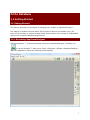
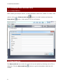
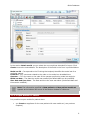
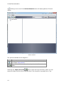
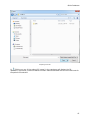
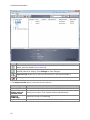
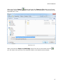
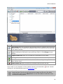
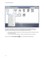
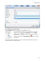
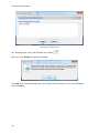
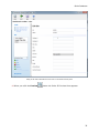
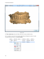
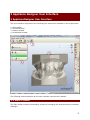
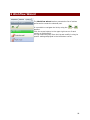
Printed Documentation
Table of Contents
Introduction .............................................................................................................. 1
Appliance Designer Glossary ........................................................................................ 3
Ortho Database.......................................................................................................... 7
1.1 Getting Started .................................................................................................. 7
1.1 Getting Started ............................................................................................... 7
1.1.1 Executing ApplianceDesigner ......................................................................... 7
1.1.2 Creating a New Database Entry ...................................................................... 8
1.1.3 Returning to the Database Entry .................................................................. 12
1.2 Preparation .................................................................................................. 23
1.3 TRIOS® ....................................................................................................... 32
2 Appliance Designer User Interface ........................................................................... 37
2 ApplianceDesigner User Interface ......................................................................... 37
2.1 Main Toolbar ................................................................................................... 37
2.2 Visualization Toolbar ........................................................................................ 40
2.3 Additional Plane Views ...................................................................................... 41
3 Interactive Tools ................................................................................................... 43
3 Interactive Tools ................................................................................................. 43
3.1 Cross-section .................................................................................................. 43
3.2 Remove Undercuts ........................................................................................... 52
3.3 3D Measurements and Custom Analysis .............................................................. 56
3.4 Articulator ....................................................................................................... 62
3.4 Articulator .................................................................................................... 62
3.4.1 How to Adapt a Parts Design in the Articulator ............................................... 70
4 Components Tab ................................................................................................... 75
4 Components Tab ................................................................................................ 75
4.1 Part ................................................................................................................ 76
4.1 Part ............................................................................................................. 76
4.1.1 Shell ......................................................................................................... 76
4.1.2 Bar ........................................................................................................... 80
4.1.3 Combine Models ......................................................................................... 85
4.1.5 Load Model ................................................................................................ 88
5 Features Tab ......................................................................................................... 93
6 Workflow Wizard ................................................................................................... 99
iii
Appliance Designer 2012™
User Manual
Introduction
Appliance Designer is a flexible program designed as a toolbox to create most of the types
of orthodontic appliances. Its structure allows a maximum of flexibility in the design
process:
• The basic tools can be applied in any sequence
• Any model can be exported for production (i.e. either a modified dentition model
used as master or the appliance itself)
• Any combination of the active 3D models is supported (addition or subtraction)
• STL library items can be applied to any 3D models
• Predefined profiles and parameters are supported
• Full export and import of design template are supported to ensure productivity and
consistency of designs
• Virtual articulation allows appliance design optimized for the patient’s specific
occlusion
1
Printed Documentation
OS-AD-1.4.0.10-A-EN
2
Appliance Designer Glossary
•
•
Part: a part is an individual element of an appliance; it consists of components and
features and will typically be manufactured individually. For example, one appliance
can be made of two separate parts: one for the upper jaw and one for the lower
which will be mounted together.
Component: a component is a building block for the appliance.
The 5 main component types are:
Shell: wrap
surface with a
fixed offset
distance.
Bar: a 3D model based
on a 2D profile, allows
to apply predefined
parameters and
geometries.
Combine models: adding or subtracting 2 models geometries
Remove undercuts: fills undercuts to simulate e.g. waxing on models
Load model: load any STL to use it as visual guide, or combine it with the appliance
Features: indicate the specific design parameters applied to a component.
Additional features, which can be applied to any active 3D model (ie not just to
components) are:
•
Additional Features:
Modify model: a sculpting toolkit to add, remove material, or smooth the model’s surface.
Attachments: allows to place an STL object from the library to the active 3D model.
3
Printed Documentation
Visual model - an attachment setup as visual model will be displayed on the screen but
will have no impact on the underlying geometry, unless one of the two following options is
chosen:
•
Additive models: when this option is chosen, the attachment geometry will be
added to the underlying model’s geometry (Boolean operation)
•
Subtractive models: when this option is chosen, the attachment geometry will be
subtracted from the underlying model’s geometry (Boolean operation)
OR
ID tags: places a unique ID tag on the active 3d model to distinguish it.
Workflows: sequence of components and features used to create an appliance or part.
Template: a template allows to reapply a given workflow to another patient model set.
4
Appliance Designer Lexicon
5
Ortho Database
1.1 Getting Started
1.1 Getting Started
This section describes the principles of managing the models in ApplianceDesigner™ .
The chapter is divided into three parts: the first part is about a new patient entry, the
second is for working on already created cases, and the third is for running an independent
session with no patient database attachments.
1.1.1 Executing ApplianceDesigner
ApplianceDesigner ™ is started by double-clicking the ApplianceDesigner™ desktop icon
or via the Windows ™ Start menu: Start->Programs->3Shape->ApplianceDesigner.
When the application starts, the following screen appears.
7
Printed Documentation
1.1.2 Creating a New Database Entry
1.1.2.1 New Patient
Before starting an analysis session, a patient database needs to be created. To create a new
patient, click on the Patient model set
New patient
button in the Main toolbar and select the
button. A New patient info form will appear.
1.2.2 New Model Set
The New model set step creates the set for the current patient by allowing you to fill in a
dialog box. Click the New model set
window:
8
button to get the New patient model set info
Ortho Database
In the section Attach model you can select the new model set intended for import. Click
Create to save the entered data. The description of the fields in the form is provided below:
Model set ID – Corresponds to the ID string that uniquely identifies the model set for a
particular patient.
Comment – Any comments related to the order or the model can be added here.
Operator – Fill in the name or the code of the operator performing model set analysis.
Model set date – The date the model was created (the default date can be modified).
Scan date and Scan time – The Date and time the scan was taken (the default date and
time can be modified).
Note: The information specified in New patient and New patient model set
appears at the bottom left corner of the session window for reference.
1.1.2.3 Open Models for Patient
It is possible to open models for patient when:
•
you Create an appliance for the new patient with new model set ( see previous
chapters)
9
Printed Documentation
•
you select Open Models
button in the Main toolbar ( becomes active when you
click Cancel in the previous case)
The Open models form appears.
Please follow the steps described below to open the existing models:
1. Choose the models for the form
General:
Select either of
the 2 models to
automatically
locate the
complimentary
model and open
the model set.
They can be
loaded in three
formats: .stl,
.wrl, .dcm.
Maxillary model:
Choose a maxillary
model only, to
load into the
system.
Mandibular
model:
Choose a
mandibular model
only, to load into
the system.
10
Ortho Database
2. Load the models to the form
To browse for a model set in the Orthodontics Control Panel, use the Browse buttons under
each of the blank fields. The default path to the folder with files of the patient database is
C:\Program Files\3Shape\OrthoData.
•
•
You may browse exclusively for the maxillary or mandibular models using the
Maxillary model or Mandibular model fields of the window.
If both parts of a model set are required, then it is possible to either select them
using the option described above or to browse for any of the two models in the
General field. The system automatically locates the pair model in the same folder to
form a properly occluded double-cast for further inspection.
3. Check Show preview to see the selections made in the preview boxes to the right of the
window.
4. Check Decimate db models to...triangles to decrease the number of triangles on the
model to a predefined value.
11
Printed Documentation
5. Click Rotate to set the appropriate rotation angle for the relational positioning of the
maxillary and the mandibular models. In the new window which pops up immediately after
you push the Rotate button, move the Rotation degrees sliding bar (minimal value being 180°, maximal 180°) to bring the rotation angle to the necessary value. View the changes
made in the preview boxes provided, to help you to control the maxillary, mandibular and
the occluded modes rotation.
6. Click Load to display the selected model(s) in the session window and start the analysis
session.
1.1.3 Returning to the Database Entry
1.1.3.1 Patient Model Set
The Patient model set option allows you to start the analysis session.
You can also start analysis session by opening an existing patient model set by clicking the
Patient model set button in the Main toolbar. Then the empty Open patient case window
pops up suggesting to search for a patient.
Open patient case window
12
Ortho Database
You can use two options to search the cases in the system:
Search
Use the Search bar in the right corner of the window to view model sets for inspection. Click
the blue triangle in the corner of the field to apply different criteria for search.
Click the Search button leaving the Search field blank to see all available model sets,
configured in the Control panel. A list of patients sorted by their IDs will appear under
Patient Selection, which would offer model set(s) for further inspection.
Advanced search
Use the Advanced search option for more precise results:
The system has several indications in the main window to help you look for the necessary
model sets in the catalogue:
13
Printed Documentation
a)
Clicking on the root of the Patient Selection tree will display patients’ IDs and
names.
Patient Selection
The options available at this stage are:
Option
Function
New patient creates a new patient in the patient database (see
the chapter New patient).
Import from file button permits to import models from other
folders.
Selecting the Import from file
button opens the Import window, where you can
select the folder the file will be imported from. The format for imported files is .3sz.
14
Ortho Database
Importing from file
b)
Clicking on one of the patient ID (name) in the catalogue will display the ID,
operators, comments, model set dates and scan dates associated with all the model sets for
the patient ID selected.
15
Printed Documentation
Option
Function
New model set allows you to create a new patient model set for the selected
patient (see the chapter New model set).
Edit patient options allows you to open the existing patient information form of the
selected patient for editing. Click Change to save changes.
Export to file allows you to save the selected file in the selected folder.*
Delete patient allows you to remove the selected patient from the list.
* The Export to file option comprises several options:
Option
Export to file
Export Trios
models without
patched areas
Export to
CAMBridge
Export to ABO
16
Function
Allows you to export the model to the selected file*.
Allows you to export Trios models without patched areas.
Exports the model to CAMBridge
Allows you to export model formatted according to the ABO format.
Ortho Database
button and select the Export to file option you will open
When you click the Export
the window, where you can select the folder where it will be exported to. The format for the
exported files is .3sz.
Exporting to file
When you select the Export to CAMbridge option from the list (the button turns to
you can observe the preview of the selected model in the Model preview window.
)
17
Printed Documentation
Model preview window
c)
Unfolding the patient model set tree further and clicking on one of the model IDs
(e.g. 2), representing the selected model set, will display seven views corresponding to this
particular model.
18
Ortho Database
Option
Function
Open model set button produces just the same effect as a double left-click on the
selected model, i.e. it submits the selected model to the analysis process opening it
in the session window.
Edit model set button opens the existing patient case information form and
suggests editing the fields which were previously filled in. Click Change to save
changes.
Prepare model set allows you to create the virtual base on the model.
New Appliance button allows you to create appliance for the selected patient case.
Refresh previews option refreshes visualization of the settings changed in the
Ortho Control Panel.
Delete model set button removes the selected model set from the list.
If the model is not prepared it will be marked with the red exclamation
clicking at it will automatically open the Preparation step.
mark. Double-
Note: There are two preview options available at this stage: small previews and
large previews. The size of the large preview images can be set in the Ortho
Control Panel. Click on the Views button on the top toolbar to select the most
convenient viewing option.
19
Printed Documentation
Throughout advancing to the last node of the selection tree, the system assists you in
tracing the order selection, as well as in managing the active selection with available
options. There are two sections in the window which perform this task:
•
•
The dark grey field at the bottom of the window summarizes the information related
to the active selection.
The top toolbar window modifies its content according to the active selection:
When you click the New Appliance
20
button the dialogue window appears.
Ortho Database
It is possible to select the template from the drop down menu. All the templates imported to
the programme will be displayed here.
Enter the Appliance id and the name and click Create to proceed.
After creating the new appliance you can observe it in the Open
patient form list. Right-click the Appliance icon select Modify
appliance info...
button from the popup menu to edit the
appliance information or Delete Appliance
the appliance.
button to remove
All of the options described above may also be accessed by right-clicking on the active
selection label (top) or image (bottom):
21
Printed Documentation
The Preview option displays the preview of the selected model. Once you click at this
option the Order 3D Preview form appears:
22
Ortho Database
Order 3D Preview form
1.1.3.2 Open Model Set
In order to complete this step, it is required that there is a patient case created (see the
chapter New Patient). Having opened a patient model set in the session window (see the
chapter Patient Model Set) you can use the Open model set
option to see the record
of just the patient case specific to the model opened. The function is provided in order to
open a different model set for the same patient and to compare models while making a
complete analysis of a single model set.
1.2 Preparation
Once you click Prepare model set
alignment
option, you are taken to the Setup plane
step once you get to the Preparation section.
23
Printed Documentation
Plane alignment section
Following the next steps will create the virtual base on the model:
1. Place the points indicating the occlusion plane following the instructions in the Plane
alignment window:
Indicating occlusion plane
2. Draw a red line on occlusion plane to create the Sagittal plane:
24
Ortho Database
Drawing a Sagittal plane
3. The Sagittal plane position can be adjusted manually (turns yellow when active):
25
Printed Documentation
Move the blue control point (1) to change the position of the plane along the Occlusal
plane. Drag the red control point (2) to change the angle of the plane.
Click OK to move to the next step.
4. You are taken to the Virtual base step.
On this step you create the virtual base using such options as Define cut, Fit Base and
Create Base.
•
26
Define cut
Ortho Database
Define cut option
Use the following options to operate through the step:
Option
Function
Upper/Lower base icons toggle the visualization of
the corresponding models for better overview.
Previous /Next operations navigation buttons.
Define cut – used to draw the cut.
Fit base – adjusts the base.
Create base - creates a new base.
Fast edit
spline
Clear
splines
Improved
bases
autosizing
If checked, allows you to place the spline by drawing
it on the surface instead of placing control points.
Removes the incorrect splines.
If checked, allows to fit the model automatically the
virtual base.
Decide on the part of the model you wish to leave, click the Define cut button if not
already at this step and place the spline points over the model curve to define the cut. Click
the first point of the spline to close it.
Adjust the spline manually by dragging the points with the cursor to the required position.
27
Printed Documentation
Editing spline
From the right-click menu options of the cursor positioned over the cutting spline you can
Add new or Remove indicated spline points, Clear spline or use Fast edit function to
correct the spline.
Hint: To create the smallest virtual bases, select the provided Arch base model
out of the base models list. You can also import your own base models.
Please refer to the Ortho Control Panel manual (chapter Construction Elements) to learn
how to add these models to the list.
Select the arch_man/arch_max base models from the drop down menu in the Select
base model section.
•
28
Fit base
Ortho Database
Once maxilla and mandible splines have been placed, click the Next or the Fit base buttons
to go to the Fit base step.
You can adjust orientation of the base by dragging the violet points and the base size with
the green points of the bounding box. Click and hold the mouse button to drag the bounding
box to the required position.
Fit base
The following parameters of the base can be modified:
Option
Show Virtual
Base
Scale
Symmetrically
Function
Toggles visualization of the virtual base.
Sets whether the bounding box is scaled
symmetrically when dragging by the green points.
Specifies the decimation amount of the base
Decimate base to
triangles (see image below).
Sets the amount of curvedness for the base
Curvature
model along the sides (see image below).
Dist. between
Specifies the distance between the maxillary and
bases
the mandibular bases.
Specifies the distance between the initial shapes
Offset
of the base and the baseless model.
Allow splines
If checked, lets the splines be placed outside the
out-of-bounds
fit base box.
29
Printed Documentation
IMPORTANT: if the cutting spline is not contained in the blue base model at the
Fit Base stage, the combined 3D model cannot be generated.
•
Create base
Once adjustments to the bounding box at the Fit base step are complete, click the Next or
Create base button to create the virtual base.
Click OK to close the Virtual base dialog window. Your models now appear to have virtual
bases.
The image below shows the virtual base using the included Arch Max and Arch Man bases
STL models:
5. Sculpt Maxillary/Mandibular
option is open automatically. Here you can trim
the results of the previous steps. Find more information on Sculpt tools in the Features
section.
to end the procedure and save the prepared model. You are
6. Click Finish
automatically taken to the Open patient case section.
Note: If you need to align jaws first you can
go back to the Occlusion step:
•
30
The Occlusion step helps to align the upper and the lower virtual casts
Ortho Database
Trans box:
1. Click on either the upper or lower casts to visualize the corresponding bounding box.
2. Drag the purple control points on the ends of the axis arrows (turn yellow) to set up the
ultimate position of the cast.
Enter the necessary values for the Maxillary distance and
Mandibular distance to move the upper and the lower casts up
and down.
Arrow buttons:
1. Click on either the upper or lower casts to visualize the green arrows.
2. Click on one of the four arrows to set up the ultimate position of the cast. Hold the CTRL
key to rotate.
31
Printed Documentation
Transition step – sets up the distance for which the cast moves up
or down at one click on the arrow.
Rotation step – sets up the degree of rotation of the model.
1.3 TRIOS®
Appliance Designer can work with the orders scanned with TRIOS®. Once you have
connected Ortho System 2012-1 to Trios (find more information on this in the Ortho Control
panel manual) you can work with the orders:
32
Ortho Database
Trios tab
1. Operation buttons indicate the actins that can be performed with the selected order.
Option
Function
Refresh option allows you to refresh the list of
the orders.
Accept allows you to accept the order and start
working with the case*.
Reject option rejects the selected order.
Accept all allows you to select all the orders in
the list.
Preview displays the preview of the scanned
model**.
* After you click Accept
button the Accept the selected orders form popups:
33
Printed Documentation
Accepting the selected orders
The selected order will be marked with the padlock
.
Once you click Accept you get the message:
Click OK. This will automatically open the Control panel Sites form. Fill in the information
and click Save:
34
Ortho Database
Filling in the Sites information for the order in the Ortho Control panel
** When you click the Preview
button the Order 3D Preview form appears:
35
Printed Documentation
Preview form
2. Trios orders tree enlists the folders with the currently available orders.
3. It is possible to open the list of options duplicating the Operation buttons by rightclicking the desired orders in the List of orders:
36
2 Appliance Designer User Interface
2 ApplianceDesigner User Interface
The user interface comprises of the following four sections as indicated on the image below:
1.
2.
3.
4.
Main toolbar
Functional panel
Session window
Visualization toolbar
The following sections describe all the user interface components in details.
2.1 Main Toolbar
The Main toolbar contains functionality relevant to managing the analysis and the processes
of design:
37
Printed Documentation
Icon
Action
Patient model set - Loads previously created patient model sets from the patient
database.
Templates - manages the templates for the program.
Rebuild all components - allows to rebuild all the loaded components.
Open models - Opens model(s) required for inspection and imports them into the
system.
Save session - Saves the current analysis session to default file.
Export models as... - Saves the current analysis session to the selected file.
Once you have selected the Export models as... button, the Export models window
appears, displaying all the models and components:
Select the path for the saved models and click OK.
It is possible to customize the general application settings. Go to Application->Preferences.
The Preferences window appears:
38
2 Appliance Designer User Interface
The Preferences window posses three
tabs.
In the Feature tree set the
parameters for the Features tab in
the ApplianceDesigner.
Language tab allows you to select
the language of the program from
the drop-down menu.
Visualization tab offers a choice of
checkboxes to customize the view of
the model in the program.
Click OK to save the settings.
The Models button opens the list of options that duplicate the
functions in the Main toolbar
The View button allows you to customize the look of
the Components tab.
It is possible to operate
with templates in the
program. Click the
button to open the
Templates window.
You can Add... to the list
of the Existing
templates. Type the
Name of the new suit
and click OK.
Use the operation
buttons to the right to
customize the section.
It is possible to
Export/Import... by
selecting the path of
export/import.
39
Printed Documentation
Note: while a template will allow to save and reapply all design parameters, and
components and features, you will still need to define the components (e.g.
cutting splines or control points) on the new patient’s model set.
2.2 Visualization Toolbar
Finding the right point of view to work on a 3D model most effectively can be difficult and
time-consuming. ApplianceDesigner comes with a set of tools aimed at helping you find the
most advantageous visualization. The visualization tools are grouped in the Visualization
toolbar and allow to:
•
•
•
•
•
Rotate the 3D view to a preset angle: this allows you to view the models from the
front, back, top, bottom etc.
Set the position of objects on the screen for analytical inspection of the models in
relation to each other.
Set the visibility of objects visualizing a part of the virtual cast, which allows for a
more detailed inspection of particular objects on the virtual cast.
Set the objects transparency for the current operation to see or hide their internal
structure.
Switch to custom rotation and panning mode enabling rotation and free movement of
objects on the screen.
The buttons in the Visualization toolbar are presented in table below:
Icon
Action
View – The view buttons allow you to switch between a number of predefined
viewpoints:
• Front view
• Rear view
• Right side view
• Left side view
• Top view
• Bottom view
Zoom all – Sets the model to the default view, size and position on the screen
leaving its current rotation angle intact.
Additional plane view - allows to view the models according to predefined
planes.
Cross-section - Allows to create the 2D cross-section of the model at any stage
of the workflow.
Show undercuts - Marks the undercuts with the colors according to the set color
scheme
3D measurements - Allows you to perform measurements on the model.
Articulator - simulates the movements of the model in the articulator.
Axis locked rotation – Locks the rotation to the x, y or z axes.
40
2 Appliance Designer User Interface
Pan view – When selected, right-click and drag to pan the view.
Zoom view – When selected, right-click and drag to zoom in and out.
Show material and shadows – Marks the cast segments with the corresponding
material colors and toggles on and off the function of shadow visualization.
Show wireframe – Shows the triangulation of the virtual casts.
Show as transparent – Changes the degree of transparency of the virtual casts.
Show perspective – Transforms the model into a realistic 3D object, where the
distant objects appear smaller than the closer ones.
Show material and shadows
Show wireframe
Show as transparent
Show perspective
2.3 Additional Plane Views
Click the Additional plane views button on the Visualization toolbar to open the
option. Select Planes configuration from the drop-down menu
Click the Add button on the Planes
window to create a new plane. Give
a name to the new plane, place
three blue arrows on the model to
mark the plane area:
41
Printed Documentation
The plane is annotated with its
name and turns yellow when
selected.
Click OK to save it.
It is possible to select now different views according to the
created plane.
Note: You can apply any custom planes created (and
saved) in OrthoAnalyzer in Appliance Designer by
choosing them from the list.
42
3 Interactive Tools
3 Interactive Tools
Interactive Tools: These tools positioned on the Visualization toolbar can be activated at
any step of the analysis and planning process.
Activation: In order to avoid conflicts in user input between the open Function and the
chosen tool (articulator, 3d measurements or 2D Cross section) and to be able to toggle
between them, click on the tools’ window to activate the given tool or on the function
window. The active feature window is marked in blue as illustrated.
3.1 Cross-section
The Cross-section button in the Visualization toolbar opens the 2D Cross-section
preview in the bottom right corner. It can be accessed at any time during the modeling
process to inspect the design
43
Printed Documentation
1. Measuring buttons
2. Cross-section plane
2D Cross section
3. Temporary plane
window
44
3 Interactive Tools
Step
1:
Draw
the
Cross
sectio
n
plane
Draw
the
red
line to
define
the
crosssectio
n
plane
by
holdin
g the
left
key of
the
mouse
.
Single
click
at the
line
create
s the
crosssectio
n.
It is
also
possibl
e to
define
a
crosssectio
n
plane
by
placin
g
three
45
Printed Documentation
points.
Use the manipulation buttons on the 2D Cross-section - Temporary plane window (2):
•
•
•
•
View buttons - unfold the number
of options that customize the view of
the cross-section plane:
Clipping plane - Left - Hides the
right side of the model in relation to
the cross-section plane.
Clipping plane - Right - Hides the
left side of the model in relation to
the cross-section plane.
Fixed camera - allows to fix the
plane in one position and move the
model instead.
Grid - turns on/off the grid of the
cross-section plane.
Standard planes - Allows you to select
the plane through which the cross-section
plane will go.
Save plane - Allows you to save the
current plane*
Clear View - Removes cross-section.
Measure area - Allows you to measure
distance on the model in the 2D Crosssection window.
Clear measure - Deletes the measures.
Zoom all - Allows you to zoom the model.
Note: You can reuse and apply any custom plane created (and
saved) in OrthoAnalyzer in Appliance Designer by choosing them
from the list of Standard planes.
option you get the popup window. Choose
* Once you have selected the Save plane
the Save as new plane option and confirm the action by giving the Name to the new
plane and clicking Save:
46
3 Interactive Tools
You can select any saved plane in Standard planes section.
Step 2: Move the
cross-section plane:
1 - The control point
located on the plane
corner rotates the plane
clockwise and anticlockwise without
moving it or changing
its slope. Thereby, you
can select the most
appropriate position of
the plane for making ongrid measurements.
2,4 - Change the slope
of the plane along the
perpendicular crosssection plane which is
perpendicular to it. To
visualize this additional
plane, activate the blue
circle by clicking on it to
make it turn yellow.
When the cursor is
positioned on the yellow
circle with its own red
control point indicating
the movement path is
displayed. While
pressing the mouse
button, drag the control
point to change the
slope of the crosssection plane.
3 - The central point
moves the plane around
the model leaving the
slope of the plane
unchanged.
5 - Plane translation:
the control point located
on the blue circle
defining the plane
47
Printed Documentation
moves the plane back
and forth without
changing its slope.
Adjust the plane
position by pulling the
Plane offset slider
on
the Temporary plane
window (2).
Length measurement requires two points. Measures length from point to point.
It is possible to customize the
view of the measurement by
right-clicking it and selecting
Properties from the popup
menu:
Select Color or the
measurement, set the Line
width from the drop-down
menu and indicate the Value by
entering the parameters
manually in the appropriate
editbox.
You can move the measurement along the grid by dragging the control point (turn white
when selected). It is possible to annotate the control point and the measurement ( if
selected turns white). Right-click the desired object, select Annotate from the popup
menu and enter the annotation text in the popup window:
48
3 Interactive Tools
Angle measurement requires three points. With angle measurement, the second
point becomes a vertex of the angle.
There are some extra
options for Angle
measurement in the
Properties option. It is
possible to select the
Revert angle or edit
the angle parameters
manually.
Distance to measurement requires one point on the desired measurement and
one point on the grid.
Spline measurement allows you to measure curved areas with the help of the
spline.
49
Printed Documentation
Distance along centre line requires two points. Measures the distance in relation
to the centre line.
Symmetry points requires one point. Automatically places the second point
symmetrically to the selected one along the center line.
50
3 Interactive Tools
Symmetry guide requires three points.
For Symmetry guide it is possible
to Show additional line and
display Distance to the center
line by marking the appropriate
options in the right-click menu.
The 2D cross section allows to take measurements automatically at the intersection of the
chosen plane and 3D model in screen. All measuring points snap to the intersection. It also
allows to take measures of area and perimeter defined by this cross-section.
The measurements placed on the model in the 2D cross section window are automatically
mirrored on the model in 3D.
51
Printed Documentation
1, 2 – The points placed on the cross-section are
automatically attached to the beige contour of the
cross-section.
3 – The system automatically builds the rightangled triangle using the selected measurement
line as its lateral face.
4 – The measurements of the other faces of this
triangle are also displayed on the cross section.
To clear the measurements made, click the
button.
Click the
Measure
Area
button and
place the
cursor over
the area you
want to
measure. The
area becomes
colored
yellow and its
value is
calculated
automatically.
Note that the
second value
is the
perimeter of
the cross
section.
It is possible to open this function on any stage of your modelling process.
3.2 Remove Undercuts
Remove undercuts fills undercuts to simulate e.g. waxing on models.
To set the Remove undercuts option follow these steps:
1. Set the remove undercuts properties
52
3 Interactive Tools
In the newly created part section click the
button in the
Part section and select the Create "Remove undercuts"
option from the drop-down list (see the image to the left).
Indicate the Name of the
new component.
Important:
the name
of the
component
corresponds
to the name
of the
Output
model!
It is possible to select
source models on which the
component is to be built by
pressing the Click button.
The All available models
window pop ups( see the
image below):
53
Printed Documentation
Note: Appliance Designer™ allows you to build any
component on either the tooth model, or on any other
component created previously.
Select the model from the list or
click Set empty to leave the
source model unidentified.
Fill in the Text that will be
displayed on the Remove
undercuts icon to the left. The
last sign in the Name section
will be duplicated in the Text
section (see the image to the
left).
Apply color, if checked, allows
you to apply the selected color
to the image
2. Remove undercuts
•
54
set the insertion direction
3 Interactive Tools
Once you get to the Features tab, you can customize the parameters for removing
undercuts in the Set insertion direction window (1).
Save as default, if checked, allows to set the selected insertion direction as default.
Show colors - indicates the areas on the model according to the Undercut depth color
scheme (3). You can observe the areas that will be removed on the model (2).
Reset to default - allows you to undo the adjustment of the insertion direction back to the
default one.
•
remove undercuts
It is possible to indicate Retention amount in the
appropriate edit box on both steps.
The Cut the model with plane button is activated on this
step. Adjust the position of the cutting plane by dragging it
and click the button.
It is possible to undo the cutting by clicking the Restore
button.
55
Printed Documentation
Click OK to apply changes.
Click Apply to save the results.
3.3 3D Measurements and Custom Analysis
The Measurements and Custom Analysis option allows you to perform and edit the
desired 3D measurements on the model.
Landmarks
Landmarks represent simple (red) points that define angles, occlusion planes, crosssections, sections for measurements etc., thus, making up to all the analysis objects
enabled by the system.
The arrow-like surface markers help you navigate around the landmarks:
Blue arrows define a passive selection.
Yellow arrows indicate the selected objects. Their positions can be changed by dragging
the corresponding marker.
The arrow turns white when you place the cursor on it.
56
3 Interactive Tools
Annotate the landmark by right-clicking it and selection
the appropriate option from the popup menu. Enter the
name of the annotation and click OK.
Customize the view of the landmarks by right-clicking
a landmark and selecting the color and form of the
landmark from the drop-down menu.
- Angles
Angles are defined by three
landmarks and the
measurements which are
immediately displayed.
It is possible to customize the
view of the measurement by
right-clicking it and selecting
Properties from the pop-up
menu:
You can open this pop-up
menu by right-clicking the
appropriate measurement in
the Custom objects window.
- Planes
57
Printed Documentation
Set a plane by positioning
three landmarks on the model.
It is possible to customize the
plane by right-clicking its name
in the Custom objects
window:
Measures
•
- direct
Place two landmarks on the surface of the model to make the measurement. It is possible to
edit it by right-clicking the measurement line (if place a cursor on it turns white, if selected
turns yellow).
58
3 Interactive Tools
Place two landmarks on the
surface of the model to make the
measurement. It is possible to
edit it by right-clicking the
measurement line (if place a
cursor on it turns white, if
selected turns yellow).
You can select the Measure type
from the drop-down menu after
right-clicking the measurement
and select Properties:
•
- calliper
Indicate the
measurement by two
landmarks replicating a
physical calliper.
Customize the
measurement by rightclicking the landmark
and opening the popup
menu.
- Distance to line
59
Printed Documentation
To make this
measurement: create
the line->place the
landmark at the area
you want to make the
measurement from>click at the selected
line
- Distance to plane
To measure the distance to plane create a plane->place a landmark on the area you want to
measure the distance from->click the green border of the plane or the annotation (if there
is):
- Custom spline
60
3 Interactive Tools
To make this measurement place
a few control points that define
the spline. Double-click the last
control point to close the spline.
To hide the measurement, click the green tick
in front of the measurement/plane.
The selected object is highlighted blue.
arrow in
To fold/unfold the groups click the
front of its name.
61
Printed Documentation
3.4 Articulator
3.4 Articulator
The Articulator option is activated with the Articulator button in the Visualization
toolbar during the design process.
1. Modify the
alignment of the
jaws
You can set the jaws in the desired positions by clicking the
button in the Virtual Articulation window and
Modify
moving the control points with the cursor for a better fit (see the
images below).
Occlusal change - The indicated value of displacement in the
occlusion direction is relative to the original static occlusal and
shown in millimeters. It can be set directly by clicking the value
and keying in the number directly or selecting it with the buttons
next to the value.
Use the buttons in the Virtual articulation window to undo your
changes to the static occlusion (1) or update the static occlusion
with the current alignment of the jaws, when you are satisfied
with the results (2).
Click the Optimize occlusion button to align jaws automatically.
The red control point allows to rotate the jaw. The blue control
point allows you to move the jaw up and down:
Set the alignment of the jaws
62
3 Interactive Tools
2. Setup articulator model
and adjust placement
Click the
button on the Virtual articulator window to start
the setup.
Select the type of the articulator from the drop-down menu
clicking the arrow button
.
It is possible to place the model in the articulator according to the
Occlusion plane, selected from the popup menu. Set up the
desired plan first in the Additional plane views section.
L Bennett, R Bennett, L cond. incl., R cond. incl. are
articulator model parameters, they can be set by clicking the
appropriate editboxes and entering their parameters manually or
selecting them with the buttons next to the values.
The Auto placement (1) button allows you to customize the
default placement method and perform auto placement of the
model. Click it to open the Auto placement options window:
63
Printed Documentation
You will need
to click the
Browse
button and
select your
placement file
to use.
The Set as
default
button saves
you current
auto
placement
method to
use as the
default one
for future
orders.
The Perform
placement
button
initiates the
auto
placements
process with
the chosen
options.
Analyze
scans is
selected for
the models
without
adaptor
plates.
You can load
predefined
planes
created in
e.g.
OrthoAnalyze
r, such as the
occlusion
plane as
default
position in
the articulator
by checking
the User
Guide plane
box and
selecting the
plane from
64
3 Interactive Tools
the dropdown list.
Use custom
placement is
used when
the adaptor
plates are
included.
Click the
Browse
button to set
the
Placement
file path.
The placement can be adjusted manually by moving the blue plane. The plane can be
moved up/down and rotated with the cursor by the indicated points to find the correct
position. It is also possible to translate the plane by dragging it. You can change the tilt of
the plane by dragging its rim:
65
Printed Documentation
Moves the
1. articulator up and
down
Rotates the
2.
articulator
Change the angle
3. of the articulator
position
Use the visibility slider
customize the view of the articulator.
in the upper right corner of the screen to
3. Use articulator to evaluate and adapt design
66
3 Interactive Tools
Click the
settings tab.
on the Virtual articulator window to open the
To set Occlusion, Laterotrusion and Pro-/retrusion you can:
•
•
Edit the parameters in the appropriate edit boxes in the
Virtual articulation window.
Move the jaws by holding the left button on the mouse (
the red control point appears and the parameters are
updated automatically).
button to change it to the unlocked
to
Click the locked
free the movement of the required plane. Place the cursor over
the articulator/model and drag it while keeping the mouse button
pressed:
67
Printed Documentation
With the Upper
/ Lower
the articulator to the static occlusion.
when resetting
Click
jaw button you can select the jaw you want to move with
to lock the modelling position of the articulator. To set the articulator in modelling
position click
.
There are three options in the Articulate function:
•
•
Contact mode - on/off/auto shut (AS) indicates the position of jaws in relation
to their penetration.
Collide designs - indicates in color the collisions of the jaws.
The Occlusal compass
map (2):
68
button allows to color the areas of collision according the color
3 Interactive Tools
The legend of the compass
Disabled it colors the areas in blue (1):
•
Record contacts - if checked, enables the Adapt design section. Indicate the Min
distance and Adaption radius by setting the parameters in the appropriate edit
boxes.
The operation can be undone with the Undo
button.
4. Simulate articulation
It is possible to imitate the articulation motions by clicking the
articulation. Click
Click the
to pause the process or
button to start the
to stop it. To repeat the process click
.
button to customize the motion sequence:
69
Printed Documentation
List of
sequences
Edit
2.
buttons
Operation
3.
buttons
Motion
4. view
section
1.
The List of sequences can be customized with the Operation buttons. Add new
sequence, Move up/down the list or Delete from the list.
3.4.1 How to Adapt a Parts Design in the Articulator
After creating the Appliance it is possible to adapt its design with the help of the
Articulator. Please follow these steps:
1. Open the component you want to adapt
Click the Feature tab and select the component you want to work with:
70
3 Interactive Tools
2. Activate the Modify Model option
Select the Modify model option to open the Sculpt:
71
Printed Documentation
Note: The active
Sculpt option is a must
for the further process.
3. Articulate
Activate the Collide designs and the 0cclusial compass to view the problem areas. Move
the jaws in the articulator by holding the pressed left mouse button and changing the
position of the red control point:
72
3 Interactive Tools
4. Adapt the appliance
Enter the desired parameters for the Cut contacts in the appropriate editbox (1) and click
the activated now Adapt design button to finish the process (2):
73
Printed Documentation
74
4 Components Tab
4 Components Tab
Components are the main
building blocks used to create
an appliance part.
The main Components are: Shell, Bar, Combine models,
Remove undercuts and Load model. The Components tab
presents the section where it is possible to operate with the
appliances for the model.
It is possible to observe the relation between the two jaws by using the color scheme.
Select both jaws and right-click the model. Select the Distance map
button:
75
Printed Documentation
4.1 Part
4.1 Part
Parts are the main elements of an appliance. Using parts allows for more
overview in the design process and to create a file that will be exported
individually. For example, for an appliance that consists of a maxillary and
mandibular element, two parts will be created individually
Click the Create new part
part and click OK.
button, give a name to the
4.1.1 Shell
A Shell is a wrap surface with a fixed offset distance.
To create a Shell you need to proceed with the following steps:
1. Set the new component properties
In the newly created part section click the
button in the
Part section and select the Create shell option from the
drop-down list (see the image to the left).
76
4 Components Tab
Indicate the Name of the
shell.
Important:
the name of
the
component
corresponds
to the name
of the
Output
model!
It is possible to select
source models on which
the component is to be built
by pressing the Click
button. The All available
models window pop ups(
see the image below):
Note: Appliance Designer™ allows you to build any component on either the tooth
model, or on any other component created previously.
Select the model from the list
or click Set empty to leave
the source model unidentified.
Fill in the Text that will be
displayed on the Shell icon to
the left. The last sign in the
Name section will be
duplicated in the Text section
(see the image to the left).
Apply color, if checked,
allows you to apply the
selected color to the image
icon.
77
Printed Documentation
Customize the color of the
model click the colored square
and select the desired color
from the palette. To get back
to the default color click the
Reset to default button.
Start now if checked allows you to be immediately taken to the Features tab for the
selected component.
Click OK to save the settings.
Alternatively, you can right-click at the
desired model and open the drop-down menu
duplicating the options in the Part tab.
2. Define a shell on a model
You need to indicate the area of the shell on the model. Place the control points to create a
spline that will define the shell.
Double-click the first control point on the spline to
close it. It is possible to edit the spline by rightclicking at it and selecting the appropriate options
from the pop-up menu.
78
4 Components Tab
From the Shell features, it is possible to set the parameters of the
shell in the Settings window:
Thickness edit box displays the thickness parameters of the shell.
Remove undercuts, if checked, removes all the undercuts visible
from the set insertion direction to ensure easy insertion of the shell on
the underlying model.
without Remove undercuts
with Remove undercuts
Retention amount allows you to define a retention factor that will
compensate for the removed undercut, depending on the material to
be used for manufacturing. If it is 0 then all the undercuts are
removed. The larger the parameter,the more retention is provided
for, in spite of the undercut removal.
Use offset for inside surface - indicates the parameters of the
offset inside the shell.
Offset - Allows you to set the offset parameters in the edit box.
Use edges smoothing - If checked, sets smoothing for the edges of
the shell.
Smooth factor - Allows to indicate the parameters for smoothing in
the edit box as a factor of the shell thickness.
Reverse spline-selected part - Reverses the splines placement that
the opposite area that originally selected will be shelled.
Click the View insertion direction button to observe the insertion
direction indicated with the blue arrow. The Set direction window
appears:
79
Printed Documentation
Show colors, if checked, displays the undercuts marked by different colors according to the
color scheme in the right bottom. This option is generally used for the Remove undercuts
step.
Click Apply to change the insertion direction according to the view on screen.
4.1.2 Bar
A Bar is a 3D model based on a 2D profile that allows to apply predefined parameters and
geometries.
Note: to be able to use Bar component, you need to define some 2D profiles of
bars in the Ortho Control Panel ( see the Ortho Control Panel manual for more
information).
To create a Bar you need follow the procedure:
1. Define the new component properties.
This step is identical to the one from the Shell setting.
2. Set a bar on the model
•
80
Set the insertion direction
4 Components Tab
Indicate the insertion direction (2) in the Set insertion direction window (1) and mark the
Show colors checkbox to observe the undercuts. The Undercut depth color scheme will be
displayed in the right corner (3).
•
Define spline
Click the Define spline
button to move to the next step or click
.
1. Central spline tab
There are two ways of placing the spline:
3D spline on models
81
Printed Documentation
Place the spline in the desired area by simply
clicking at the surface of the model.
Click Next to continue.
2D spline on models
To place the central spline in 2D
mode select the plane from the
Plane drop-down menu (you
have to create the desired planes
before this. For more information
see the Additional Plane Views
section).
Adjust the plane in the Offset
edit box.
Place the spline of the plane and
click Next. To redo the spline
click Clear spline. Otherwise,
right-click the spline to edit it:
2. Fixed-on-model spline
This option allows to create a secondary spline to limit the lower part of the bar. Click Next
to move to the following step.
82
4 Components Tab
•
Create Bar
Click the Create Bar
points:
button. The bar on the model if formed. Align it using the control
Important: the Bar should be created previously in the Control Panel ( see the
Ortho Control Panel manual for more information).
Hold the right button of the mouse and pull the control point (becomes yellow when active)
to the desired position. Use red control points to rotate the bar segments round their axis.
Green points allow you to squeeze/stretch the bar. Blue control points move the bar
up/down in relation to the model surface. Purple control points stretch/shorten the general
length of the bar.
Double click at the blue control point cuts the bar at the control point for easy inspection
(2). To undo the cutting double click the control point once again (1):
83
Printed Documentation
Click Adjust width to set automatically the bar width to that of the underlying model.
Select the type of the Bar ending from the drop-down menu (Flat or Wrap around).
In case you have selected the Fixed-on-model spline type, mark the Use fixed-on-model
checkbox. Fit bar surface to spline, if checked, automatically aligns the bar to the
secondary spline.
Press Shift to select all the control points.
Press Ctrl to select some points only.
Right-click the selected control point to open the
popup menu. With this option it is possible to
move all selected control points to a common
plane.
84
4 Components Tab
Once you place a mouse over
the green segment a red
control point appears. Rightclick the point to open the popup menu.
The linear option creates
straight segments only and the
control points are positioned
between them.
The free form option resets all
the segment to their original
states.
•
Finish
Click the Finish
button to finalize the process.
Select one of the four options enlisted in the section.
Merge with model upper/lower part is available only for the bars created with the fixedon-model spline.
Combine bar with other model. Indicate the Remove undercuts retention amount
parameters in the edit box for the Substract reference model option.
Click OK to apply the adjustments and exit the current feature step.
Click Apply to make the changes but remain on the current step.
4.1.3 Combine Models
Combine models feature allows you adding or subtracting 2 models geometries.
To use this option follow the next steps:
1. Set the new component properties
This step has the same procedure as the one for the Shell setting (for more information see
the Shell chapter).
Important: the model you want to subtract from should be selected first from the
list of the models.
2. Combine the selected models
85
Printed Documentation
Use the Operations tab in the left bottom corner of the
screen to select the type of combination:
•
Combine - allows you to combine two models’ geometry into one new solid model
Bar before Combining
•
86
After Combine
Subtract - will carve one model’s geometry according to the other selected model.
4 Components Tab
Bar before Subtracting
•
After Subtracting
Extra Combine - allows to combine two models while carving the underlying
dentition automatically.
87
Printed Documentation
Shell and Bar before Extra Combine
Shell and Bar after Extra Combine
For higher results mark the Check and Repair models checkbox.
Click OK to view the result of the process.
Click Apply to save the changes.
4.1.5 Load Model
It is possible to load any STL model to the Components
section. Contrary to the Attachments , loaded models
don’t need to be fixed on another 3D model. They get their
own view slider which allows to view them as design guides
without affecting the actual design process.
in the Part section and select Load model in the
Click
popup menu. The New component properties window is
open (see the settings for it in the Shell section).
In the Select source model section indicate the path a model is loaded from.
88
4 Components Tab
It is possible to observe the model preview. Mark the Copy file to model set folder
checkbox to save the copy of the model.
After loading model it is possible to
align it. Right-click it and select the
Add "Align model" option in the
popup menu. The Registration
window appears:
89
Printed Documentation
Follow the instructions at the top of the Registration
window.
The Reference model button opens the list of the available
models.
You can select the type of alignment:
•
•
•
Surface 1-point: Indicate single corresponding
points on each model for alignment and optionally
select the surface to align with the help of the
Selection Tools.
Surface 3-point: Indicate three corresponding
points on each model for alignment and optionally
select the surface to align using the Selection Tools.
Direct 3-point: Indicate three corresponding points
on each model for alignment. This method does not
use the surface information.
Note: It is advisable to use the Dual view
visualization in order to access both models at
the same time. The selection of points can be
done on the reference model first and then on
the comparative model, or vice versa. Use the
Reset button to delete the reference points if
needed.
Reference
model
2. Model
3. Selection
1.
90
4 Components Tab
tools
The selection tools can be used in any order and combination. They include the following:
Icon
Function
Unselect all – Unselects all selections
Reduce selection – Reduces the selected area by
excluding the neighboring areas from the selection.
Extend selection – Extends the selected area by
adding the neighboring areas to the current selection.
Invert selection – Unselects the selected and
selects the unselected areas of the surface.
Undo last selection – Makes one step back in the
selection operation
Paint selection – Use the brush tool to "paint" the
model reference surface while keeping the left mouse
button pressed.
Click Apply to perform the changes but remain on the current step.
Click OK to apply the alignment and exit the current option.
91
5 Features Tab
The Features are the parameters of components as
described in this section. But there are also additional
features that can be applied to an existing component. It is
automatically open if you have marked the Start now
checkbox while creating the new component.
It is possible to use the Current workflow wizard operation buttons to customize your
steps:
The Previous button allows you to
undo the changes.
The Next button allows you to move
to the next step.
The Done button finalizes the
customization process.
The Add Feature button opens the
drop down menu with additional
features:
•
Add "modify model"
The modify model is a sculpting toolbox that allows you to make local changes to
the selected component or model’s geometry.
This option adds the Modify model step to the selected component or model.
This is applicable, when you have created a certain appliance and need to trim it. The Sculpt
window is open:
The Wax knife
option allows you to add
or remove surface on the selected area. Click
button in the Wax knife settings
the Add
section to add some material to the scan. The
target area circle is marked red. Select the
Remove
button to delete extra material
or click the Smooth
button. The target
area circle is marked blue and green
respectively. Adjust the Radius and Level of
the marking circle by pulling the
corresponding slide bars. It is possible to use
the already customized settings from the list of
six variants. Activate the desired mode by
93
Printed Documentation
clicking at its number in the list. To change the
setting for the mode set the parameters in the
Wax knife settings section and click the Save
button. Mark the Show target area
checkbox to display the marking circle.
The Morphing
option allows to force in
and out the curve on the surface. You can set
the radius of the marking circle by pulling the
Radius slidebar.
Note: the green outline
indicates that the
model’s edge will be
affected by the
morphing process.
The Plane cut
option allows to cut the
selected parts of the appliance with the plane.
Draw the red line by holding the left button of
the mouse. The cut plane is created. The green
arrow indicates the cutting direction. You can
move the cutting plane by pulling the blue
control point or set the parameters in the
Offset edit box. You can select the already
created plane by choosing it from the Default
planes drop-down list. It is possible to adjust
the size of the cutting plane by marking the
Local plane cut checkbox. Set the parameters
for Smooth radius in the appropriate edit
box. If marked the Show cut-off part shows
the section that was cut. To select another side
of the plane cut click Swap cut direction.
Click Clear to delete the plane cut.
The Spline cut
option allows to cut-off
the parts of the appliance using the splines.
Mark the desired area with the splines. It will
be circled with green line and the rest of the
model will be transparent. It is possible to
Save parameters for this option or Load the
already existing on another model. Select the
Spline type. Set the Fillet radius and Plane
offset parameters in the corresponding edit
boxes. Use the Reverse Direction button to
change swap the selected area. Mark
Additional plane cut checkbox to create the
additional plane.
94
Features1
Use the Global transformations
option
to stretch/squeeze the appliance to the desired
length and height. Use the green and red
control point to move the appliance. Hold the
left button of the mouse and pull the control
point in the desired direction. You see the ruler
to view the numerical information on the
movements you perform. It is possible to
rotate the appliance by pulling the red control
point. Click OK to apply the changes.
You can Undo/Redo the operation by clicking the appropriate buttons. It is
possible to view the history of actions performed by clicking the black arrow
by each button.
It is possible to observe the changes you perform in colors. Activate
the Difference map by clicking the appropriate button. Open the
drop-down menu by clicking the black arrow to view the legend and
customize its view.
•
Add "Attachments"
Attachments are 3D models that can be added to or subtracted from the surface of any
model, or simply used as visual guides for the output models or appliances.
Note: attachment should be added to an attachment group through the Ortho
Control Panel before they are available in the Appliance Designer.
Click on the desired area and place the attachment. Customize it using the red, green and
blue control points:
95
Printed Documentation
Rotates attachment
Changes the height of
4.
round its axis
attachment
Moves the attachment in
Changes the width
2.
5. relation to the surface of the
of attachment
appliance
Moves the
3. attachment back
and forward
1.
Note: Attachments properties can be edited in the Ortho Control Panel: it is for
example possible to lock the scaling parameters (i.e. 2 and 4 in the image above),
so the attachment’s geometry cannot be changed during the design process. This
is particularly useful when attachments are standard physical parts that will be
mounted in the designed appliance.
It is possible to select the Group, type of Attachment and Default orientation by
choosing them from the corresponding drop-down menu in the Attachment settings window.
•
Add "ID tag"
ID Tags allow you to add easy identification
to any output model for easy sorting in the
manufacturing equipment.
Click at the desired area on the model. It is possible adjust the ID tag in the desired
position with the help of the blue and purple control points on the joystick:
96
Features1
Changes the angle of ID tag
1. position according the
surface
Moves the ID You can setad
2. along the surface of
appliance
Rotates the ID tag round its
3.
axis
You can customize the look of the Id tag in the ID Tag generation window. Type the ID
Text and select the drop-down menu (Detachable or Integrated).
Indicate the Text Depth and Font Height in the appropriate edit boxes (for Integrated ID
Tag type).
Place one control point in the desired area to indicate the detachable ID tag and click OK to
view the result:
97
Printed Documentation
Set Connectors count and Min. distance to Model in the corresponding edit boxes (for
Detachable ID Tag type).
98
6 Workflow Wizard
The Workflow wizard section presents the list of actions
performed to create the selected part.
It is possible to navigate the list by using the
or
buttons.
Click the arrow buttons in the upper right corner of each
section to fold/unfold it.
You can select any step from the list and modify it using its
specific settings displayed in the left bottom corner.
99