1
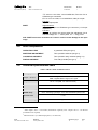
Technical
Information
Manual
Revision n.3
3 March 2004
MOD. V993
DUAL TIMER
MANUAL REV.3
NPO:
00114/00:V993x.MUTx/02
CAEN will repair or replace any product within the guarantee period if the Guarantor declares
that the product is defective due to workmanship or materials and has not been caused by
mishandling, negligence on behalf of the User, accident or any abnormal conditions or
operations.
CAEN declines all responsibility for damages or
injuries caused by an improper use of the Modules due
to negligence on behalf of the User. It is strongly
recommended to read thoroughly the CAEN User's
Manual before any kind of operation.
CAEN reserves the right to change partially or entirely the contents of this Manual at any time
and without giving any notice.
Document type:
User's Manual (MUT)
Title:
Mod. V993 B Dual Timer
Revision date:
03/03/2004
Revision:
3
TABLE OF CONTENTS
1.
MODULE DESCRIPTION ........................................................................................................................4
1.1.
2.
3.
OVERVIEW .............................................................................................................................................4
TECHNICAL SPECIFICATIONS............................................................................................................5
2.1.
PACKAGING ............................................................................................................................................5
2.2.
POWER REQUIREMENTS ..........................................................................................................................5
2.3.
FRONT PANEL .........................................................................................................................................6
2.4.
SIGNALS FEATURES ................................................................................................................................7
2.5.
OTHER COMPONENTS .............................................................................................................................8
2.6.
TECHNICAL SPECIFICATIONS TABLE........................................................................................................8
OPERATING MODES ...............................................................................................................................9
3.1.
INSTALLATION........................................................................................................................................9
3.2.
TIMER TRIGGERING ................................................................................................................................9
3.3.
OUTPUT WIDTH ADJUSTMENT ...............................................................................................................10
3.4.
OUTPUT LEVEL SELECTION ...................................................................................................................10
3.5.
LEDS OPERATION .................................................................................................................................10
LIST OF FIGURES
FIG. 2.1: MODEL V993 B FRONT PANEL ................................................................................................................6
LIST OF TABLES
TABLE 2.1: POWER REQUIREMENTS .......................................................................................................................5
TABLE 2.2 MOD. V993 B TECHNICAL FEATURES ..................................................................................................8
NPO:
00114/00:V993x.MUTx/03
Filename:
V993B_REV3.DOC
Number of pages:
10
Page:
3
Document type:
User's Manual (MUT)
Title:
Mod. V993 B Dual Timer
Revision date:
03/03/2004
Revision:
3
1. Module description
1.1. Overview
The Model V993 B Dual Timer is a 1-unit VME module housing two identical triggered
pulse generators.
The module produces NIM, TTL and ECL pulses whose width ranges from 50 ns to 10 s
when triggered. Output pulses are provided normal (OUT) and negated (/OUT).
Timers can be re-triggered with the end marker signal.
The coarse adjustment of the output width is provided via a 9-position rotary switch, the
fine adjustment can be performed via either a rotary handle or by providing an external
voltage (WSET).
The trigger START can be provided via either an external signal (NIM, TTL or ECL) or
manually via a front panel switch (START/RESET switch).
The VETO input (NIM, TTL or ECL TRUE level) allows to disable the START operation.
The ENDM output (NIM, TTL or ECL) is a short pulse produced at the end of any timing
cycle.
The RESET input (NIM, TTL or ECL) ends the timing cycle at any time. RESET can also
be provided manually via a front panel switch (START/RESET switch).
See § 2.4 for details about signals.
The module features LEMO 00 connectors for WSET and NIM/TTL signals and male pin
couples for ECL signals. Two front panel LEDs display when the module is operating.
The board is equipped with the P1 connector.
Two internal switches allow to select between NIM and TTL output pulses, while input
levels are automatically recognised (no selection is required).
NPO:
00114/00:V993x.MUTx/03
Filename:
V993B_REV3.DOC
Number of pages:
10
Page:
4
Document type:
User's Manual (MUT)
Title:
Mod. V993 B Dual Timer
Revision date:
03/03/2004
Revision:
3
2. Technical specifications
2.1. Packaging
The Model V993 B is housed in a 6U-high, 1U-wide VME unit. The board hosts the VME
P1 connector.
2.2. Power requirements
The power requirements of the versions available for the V993 B module are as follows:
Table 2.1: Power requirements
NPO:
00114/00:V993x.MUTx/03
+5 V
2.3 A
+12 V
60 mA
-12 V
300 mA
Filename:
V993B_REV3.DOC
Number of pages:
10
Page:
5
Document type:
User's Manual (MUT)
Title:
Mod. V993 B Dual Timer
Revision date:
03/03/2004
Revision:
3
2.3. Front panel
Mod. V993
START
VETO
10 ms
COARSE
ADJUSTMENT
.1 s
1s
1 ms
.1 ms
10 s
10 µs
∞
1 µs
WSET
R
L
0 - 5V
0
9
FINE
ADJUSTMENT
WSET/FINE ADJUSTMENT
SWITCH
1
8
2
7
3
6
4
5
RESET
START
RESET/START
SWITCH
OUT
/OUT
ENDM
ST
VETO
RESET
ENDM
OUT
/OUT
- +
START
VETO
10 ms
.1 s
1s
1 ms
.1 ms
10 s
10 µs
∞
1 µs
R
WSET
L
0 - 5V
9
0
1
8
2
7
3
6
4
5
START
RESET
OUT
/OUT
ENDM
ST
VETO
RESET
ENDM
OUT
/OUT
- +
DUAL TIMER
Fig. 2.1: Model V993 B front panel
NPO:
00114/00:V993x.MUTx/03
Filename:
V993B_REV3.DOC
Number of pages:
10
Page:
6
Document type:
User's Manual (MUT)
Title:
Mod. V993 B Dual Timer
Revision date:
03/03/2004
Revision:
3
2.4. Signals features1
START INPUT:
Signal features:
NIM: Leading edge sensitive, 2.5 ns minimum FWHM on
LEMO 00 type connector
TTL: Leading edge sensitive, 1.5 ns minimum FWHM on
LEMO 00 type connector
ECL: Leading edge sensitive, 2.5 ns minimum FWHM on a
male pin-couple
START/RESET Switch2: Momentary switch for single cycle
operation
Function:
Timer triggering signal
VETO INPUT:
Signal features:
NIM/TTL: TRUE level (within ±2 ns of START leading edge)
on LEMO 00 type connector
ECL: TRUE level (within ±2 ns of START leading edge) on a
male pin-couple
Function:
It disables triggering
RESET INPUT:
Signal features:
NIM/TTL: Leading edge sensitive, 3 ns minimum FWHM on
LEMO 00 type connector
ECL: Leading edge sensitive, 3 ns minimum FWHM on a
male pin-couple
START/RESET Switch2: Momentary switch
Function:
It stops the timing cycle at any time. After a RESET the
module is at rest until the next START.
ENDM OUTPUT:
Signal features:
NIM: 8 ns wide on LEMO 00 type connector
TTL: 10 ns wide on LEMO 00 type connector
ECL: 8 ns wide on a male pin-couple
Function:
It marks the end of the timing cycle
OUT:
Signal features:
NIM: 50 ns to 10 s wide, 2 ns rise/fall time, Fan-Out of 2 on
LEMO 00 type connectors
TTL: 50 ns to 10 s wide, 4.5 ns rise/fall time, Fan-Out of 2 on
LEMO 00 type connectors
ECL: 50 ns to 10 s wide, 2 ns rise/fall time, male pin-couple
Function:
Output pulse
/OUT:
Signal features:
NIM: 50 ns to 10 s wide, 2 ns rise/fall time, Fan-Out of 2 on
LEMO 00 type connectors
1
All ECL inputs are 110 Ω terminated, all NIM/TTL inputs are 50 Ω terminated
2
START and RESET share the same 3-position switch: Left → RESET, Middle → NEUTRAL
(stable), Right → START
NPO:
00114/00:V993x.MUTx/03
Filename:
V993B_REV3.DOC
Number of pages:
10
Page:
7
Document type:
User's Manual (MUT)
Title:
Mod. V993 B Dual Timer
Revision date:
03/03/2004
Revision:
3
TTL: 50 ns to 10 s wide, 4.5 ns rise/fall time, Fan-Out of 2 on
LEMO 00 type connectors
ECL: 2 ns to 10 s wide, 2 ns rise/fall time, male pin-couple
Function:
Negated output pulse
WSET:
Signal features:
0 to 5 V DC input on LEMO 00 type connector (1 kΩ input
impedance)
Function:
It allows to perform the output pulse fine adjustment via an
external voltage: 0 V → “short” pulse, 5 V → “long” pulse
N.B.: WSET must never exceed the 5 V value in order to avoid damage to the input
stage.
2.5. Other components
OPERATION LEDS:
2 green/red LEDs (see § 3.5)
WSET/FINE ADJUSTMENT:
Two 2-position switches (see § 3.3)
COARSE ADJUSTMENT:
Two 9-position rotary switches (see § 3.3)
FINE ADJUSTMENT:
Two rotary handles (see § 3.3)
2.6. Technical specifications table
Table 2.2 Mod. V993 B Technical Features
1U-wide VME unit
Packaging
OUT: NIM/TTL signal with a Fan-Out of 2, ECL signal
/OUT: negated NIM/TTL signal, ECL signal
Output3 / Section
50 ns ÷ 10 s (NIM, TTL and ECL levels)
Output width
WSET
0÷5V
START/OUT delay6
<25 ns
RESET delay
~30 ns: the timing cycle stops ~30 ns after the RESET pulse is sent
Rise/Fall Time
< 2 ns
Thermal stability4
3
-60 ppm/°C
NIM outputs drive a 50 Ω load (termination required), ECL outputs drive a 110 Ω load
(termination not required)
4
Measured with a 1 µs NIM output pulse (1 ms full scale)
NPO:
00114/00:V993x.MUTx/03
Filename:
V993B_REV3.DOC
Number of pages:
10
Page:
8
Document type:
User's Manual (MUT)
Title:
Mod. V993 B Dual Timer
Revision date:
03/03/2004
Revision:
3
3. Operating Modes
3.1.
Installation
The V993 B board is provided with the P1 connector only, so it is suitable for both
standard VME 6U and VME V430 crates.
CAUTION
ECL INPUTS ARE SUSCEPTIBLE TO DAMAGE FROM ESD
(ELECTROSTATIC DISCHARGE). TO PREVENT THE RISK OF DAMAGING,
THE USER SHOULD NEUTRALIZE ANY STATIC ELECTRIC CHARGE BUILT UP
ON THE BODY (e.g. TOUCHING AN EARTHED OBJECT) BEFORE
HANDLING THE ECL CONNECTORS
CAUTION
ALL CABLES MUST BE REMOVED FROM THE FRONT PANEL BEFORE
EXTRACTING THE BOARD FROM THE CRATE!
3.2. Timer triggering
The board has two sections housing one triggered pulse generator each. Each section
produces an adjustable width pulse when triggered. The trigger START signal can be
sent as external NIM/ECL signal on the relevant START connectors or by pulling towards
right the START/RESET switch (see § 2.4). Note that output pulses are not retriggerable:
the START signal/switch is inactive as long as the output status is true.
NPO:
00114/00:V993x.MUTx/03
Filename:
V993B_REV3.DOC
Number of pages:
10
Page:
9
Document type:
User's Manual (MUT)
Title:
Mod. V993 B Dual Timer
Revision date:
03/03/2004
Revision:
3
3.3. Output width adjustment
Each section has a 9-position rotary switch for performing the COARSE ADJUSTMENT
(see § 2.5). Actually this switch allows to choose between nine width ranges:
50 ns ÷ 1 µs
1 µs ÷ 10 µs
10 µs ÷ 0.1 ms
0.1 ms ÷ 1 ms
1 ms ÷ 10 ms
10 ms ÷ 0.1 s
0.1 s ÷ 1 s
1s ÷ 10 s
∞: Flip-Flop
Actually the 9th position (∞) lets the module work as a Flip-Flop: the output is kept active
unless a Reset occurs. Once the COARSE ADJUSTMENT is set, the FINE
ADJUSTMENT must be performed either by turning the relevant rotary handle or by
supplying the WSET connector with a DC voltage ranging from 0 to 5 Volts: the
WSET/FINE ADJUSTMENT SWITCH allows to select between the two ways:
Left → WSET, Right → Rotary Handle (see § 2.5).
3.4. Output level selection
Two dip switches (one per section, named SW4 and SW8 respectively) allow to produce
either NIM or TTL pulses on the LEMO 00 output connectors. The switches’ setting is:
Dot NOT visible → NIM
Dot visible → TTL
Such swithces are placed on the printed board, close to the front panel. ECL output
pulses are produced in any case on the relevant male pins.
3.5. LEDs operation
The front panel LEDs are OFF when no output is present; they light up following the
output with widths larger than 0.5 s; they light up for a fixed time (≈0.5 s) with output
pulses shorter than 0.5 s. They flash at a constant frequency (≈2 Hz) with output
frequencies higher than 2 Hz. They light up red for NIM output pulses and green for TTL
ones.
NPO:
00114/00:V993x.MUTx/03
Filename:
V993B_REV3.DOC
Number of pages:
10
Page:
10