1
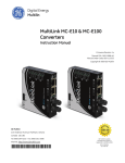
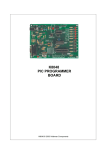
PVK40 User's manual Feature Rich Development and Educational Kit for 40-pin Microchip PIC® microcontrollers CONTENTS PVK40 On-board peripherals: 3 3 Power supply 4 Microcontroller 4 Reset circuitry 4 Oscilator 4 Ports Port usage on PVK40 board PORT A PORT B PORT C PORT D PORT E 5 5 5 5 6 6 6 Peripheral description LED diode LED display BARGRAPH Pushbuttons BT0 .. BT7 Buzzer Microphone (MIC) Photoresistor (PHOTO) Thermo sensor (TEMP) Potentiometers (TRIM1, TRIM2) Infrared remote control (IRF_TX, IRF_RX) RS-232 interface (COM) USB interface (USB) EEPROM memories (24xx, 25xx, 93xx) DIP switches Expansion connector PROGRAM connector MONIT connector LCD display connector 6 6 6 7 7 7 7 7 7 7 7 8 8 8 8 9 9 9 10 Schematics 11 PCB layout 13 Recommended add-ons 14 Contact 14 Page 2 / 14 PVK40 PVK40 is a feature rich development board for the 40-pin PIC® Flash MCUs PIC16F87x, PIC16F7x, PIC18Fxx. The board includes all the circuitry necessary for an in-depth study of most of the microcontroller on-chip peripherals and for experimenting with several external peripherals. This board will help you to become an expert in PIC MCU programming. The 40-pin PIC MCUs contain a superset of the periperals found in the lower pin count devices, while the register mapping is still compatible. This is the reason why all the knowledge and experience gained on the 40-pin devices apply also to practically all other PIC® microcontrollers. On-board peripherals: Two potentiometers connected to the A/D converter inputs Photoresistor connected to the A/D converter input Microphone with preamplifier connected to A/D converter input Thermo sensor 24LC01 - I2C Serial EEPROM Sockets for other types of serial EEPROMs (MicroWire - 93xx, SPI - 25xx) RS232 driver and 9-pin SubD connector Socket for USB-to-serial module UMS1 (with FTDI FT232 chip) and EEPROM IR LED (transmitter) IR receiver with 36 kHz filter and demodulator 4-digit 7-segment LED display 10 level bargraph Interface for LCD character dot matrix display Page 3 / 14 LED diode 8 pushbuttons Buzzer (connected to the PWM output pin) Crystal 3.2768 MHz Position to connect RC oscillator Position for crystal Reset button ICSP/ICD connector (In-Circuit Serial Programming/In-Circuit Debugging) Application monitoring connector (INSIDER interface) Expansion connector with all microcontroller signals DIP switches for connecting/disconnecting the peripherals Stabilized 5 Volt power supply Power supply A power supply with voltage of 9 .. 12 V can be used. The power consumption varies according to peripherals being used and/or external circuitry powered from the board. A power supply which can deliver 300 mA and more is recommended. Microcontroller The 40-pin Flash PIC microcontrollers are supported, e.g.: PIC16F74 PIC16F77 PIC16F871 PIC16F874, PIC16F874A PIC16F877, PIC16F877A PIC18F442 PIC18F448 PIC18F452 PIC18F458 PVK40 is delivered with PIC16F877-20/P device. Further it is possible to use any microcontroller with compatible pinout. Reset circuitry The -MCLR pin is connected through pull-up resistor to +5V, thus preprogrammed microcontroller starts running just after power is applied (if the oscilator is connected and set up properly). In addition the RESET button can be used to force microcontroller reset. Oscilator The board is equipped with 3.2768 MHz crystal which can be connected to microcontroller by turning on the XT 3.276M DIP switch. Otherwise either a crystal soldered to prepared XT position or RC oscilator soldered to R and C positions may be used. In such case the XT 3.276M DIP switch must be turned off. Note: only one of the crystal or RC oscilator can be connected at a time. Page 4 / 14 Ports Most of the supported microcontrollers are capable of analog to digital conversion at port A inputs, thus analog circuitry is connected to these pins (thermo sensor, photo resistor, 2 potentiometers and microphone). Port B is general purpose, digital. It is used to drive display anodes, LED, infra LED. Serves also for in-circuit programming. Some of the port C pins have special capability and are used for IR receiver, bargraph, buzzer, UART and EEPROM memory. Port D is general purpose, digital. The display, bargraph and pushbuttons connect to its pins. Port E has only 3 pins which are used for 2 remaining bargraph segments and application monitoring connector. Port usage on PVK40 board PORT A Port A bit 0 bit 1 bit 2 bit 3 bit 4 bit 5 Pin Type analog input analog input analog input analog input analog input output Function thermo sensor (TEMP) photoresistor (PHOTO) potentiometer 1 (TRIM1) potentiometer 2 (TRIM2) unused microphone with preamplifier (MIC) CS signal for 93xx EEPROM PORT B Port B bit 0 bit 1 bit 2 bit 3 bit 4 bit 5 bit 6 bit 7 Pin Type output output output output output output Function log.0 activates first (lowest) display digit log.0 activates second display digit log.0 activates third display digit log.0 turns on standalone red LED log.0 activates fourth (highest) display digit log.1 turns on IR LED (IRF_TX) reserved for ICSP programming (CLK) reserved for ICSP programming (DATA) Page 5 / 14 PORT C Port C bit 0 bit 1 bit 2 bit 3 bit 4 bit 5 bit 6 bit 7 Pin Type input output output input/output input/output output output input Function IR receiver (IRF_RX) log.0 activates bargraph buzzer EEPROM: clock signal - 25xx, 24xx, 93xx EEPROM: data out for 25xx, 93xx, SDA for 24xx EEPROM: data in for EEPROM 25xx, 93xx UART_TX or -CS for EEPROM 25xx UART_RX PORT D Port D Pin Type bit input 0..7 output Function button state – log.0 = button BT0..BT7 is pressed log.0 tuns on segment A..G, DP of active display digit or segment 1..8 of bargraph In case the LCD module is used, PORT D serves as the data bus. PORT E Port E Pin Type bit 0 output bit 1 output bit 0..2 Function log.0 turns on segment 9 of bargraph log.0 turns on segment 10 of bargraph MONIT - connector for application (INSIDER) monitoring device Note: If the peripherals are disconnected using DISPSW1 or DISPSW2 switches, user peripherals may be connected to unused microcontroller pins using expansion connector. Peripheral description LED diode Red LED diode can be turned on by setting bit 3 of port B as output and writing log.1 to it. Writing log.0 turns the LED off. LED display 7-segment LED display devices are used. The display is designated to be used in multiplexed mode. The segment is on if there is log. 0 on the appropriate bit of the port D (which selects a segment) and at the same time log. 0 is on the appropriate pin of the port B (which selects a 7-segment device). If the switching is fast enough (>25 Hz), display shows characters without noticable flashing of the segments. Page 6 / 14 BARGRAPH The bargraph is controlled the same way as display. A segment is on if appropriate bit of port D is set to log.0 (selects a segment to be lit), and at the same time bit 1 of port C is set to log.0 (selects the bargraph). Remaining segments (9 and 10) are driven from port E, bit 0 and 1. Pushbuttons BT0 .. BT7 Reading data from port D defined as input allows to detect the state of the pushbuttons. Log.0 on the appropriate pin indicates that the button is pressed. Since the buttons are serially connected with resistors, no short connections appear when a button is pressed, which ensures that the display can be controlled concurrently while reading the buttons in meantime. Buzzer Buzzer is connected to pin C1 which can be also configured as PWM output thus sounds can be generated easily. Because the buzzer acts as a capacitor, it is connected directly to microcontroller pin – the DC part of the signal does not affect its operation. Microphone (MIC) An electret microphone MCE100 is used. Preamplified signal is connected to pin A5. Photoresistor (PHOTO) Photoresistor to sense light intensity is provided. Its response is pretty slow, (1/10 s to several seconds), but the sensitivity is high. The photoresistor is connected in a voltage divider output of which is wired to pin A1 of the microcontroller. Thermo sensor (TEMP) Its resistance changes with the temperature. It is connected in a voltage divider which is balanced at about 20°C. The output of the divider is wired to pin A0. Potentiometers (TRIM1, TRIM2) The potentiometers are connected to pins A2 and A3 and can deliver a voltage of 0 to 5 V to these pins, which is convenient for testing of A/D converter function or setting a parameter of application program. Infrared remote control (IRF_TX, IRF_RX) This part of the board can be used as both IR receiver and transmitter compatible with most remote controlled consumer electronic products like TV, Hi-Fi, DVD players and so on. The board contains a receiver with 36 kHz filter and demodulator, thus the signal to be received must be modulated at about this frequency. The IR LED can be used to transmit modulated signal. It is possible to communicate between two PVK40 boards this way. If it is desired to test the Page 7 / 14 communication with a single board only, an object reflecting the IR light (e.g sheet of paper) must be placed nearby the receiver and transmitter. The IR LED is turned on by log.1 on B5 pin. The LED is typically driven by pulses with momentary current reaching 0.5 A. In case of PVK40 the current is only 60 mA, thus the range of the transmitter is smaller, but leaving the LED accidently on will not result to its damage. The receiver is connected to C0 pin and delivers digital demodulated signal. RS-232 interface (COM) This type of interface is still common part of most computers. Its levels are +12V for log.0 and -12V for log.1. The cable may be several tens of meters long. The level converter between TTL and RS-232 is part of the board and is connected to UART of the microcontroller, pins C6 and C7. Jumper JP2 and JP3 can be used to shorten pins 7 (RTS) and 8 (CTS) of SubD 9-pin connector or pins 4 (DTR) and 6 (DSR) respectively. If the RS-232 interface is to be used, jumper JP4 must be set to COM-RX position. USB interface (USB) This fast and convenient interface is recently getting popular and is wide spreaded in PC world these days. Since the USB communication is much more complicated than for example RS-232, there are integrated circuits which cover its complexity. One of the possibilities is FT232 by FTDI Ltd. (www.ftdichip.com) which is able to communicate with the microcontroller serially at speeds up to 1 MBaud and it is possible to connect it directly to UART of the microcontroller. The drivers for common operating systems (Windows, Linux, MacOS) are available from FTDI for free. A module UMS1 (available from ASIX) equipped with this circuit fits directly into socket on PVK40 board. It is also possible to connect an EEPROM memory with USB configuration data (although this is not an necessity). More information can be found on websites www.pic-tools.com and www.ftdichip.com. If USB communication is to be used, it is necessary to set jumper JP4 to RX-USB position. EEPROM memories (24xx, 25xx, 93xx) There are sockets for popular serial EEPROM memories available onboard. 24LC01 is part of the PVK40. It is possible to test all standard communication protocols I2C, MicroWire and SPI. In case of MicroWire memories, data organization (8 or 16 bit) can be set using jumper JP1. The wiring to microcontroller pins can be found in PVK40 schematics. DIP switches Most of the peripherals can be disconnected from the microcontroller using DIP switches. This is convenient if the user wishes to connect custom peripherals. If the onboard peripherals are to be used, remember to set appropriate DIP switches to ON position. Page 8 / 14 Expansion connector A 40-pin connector with all microcontroller signals is placed in the lower left part of the board. This connector can be used to connect user peripherals. The pinout corresponds with the microcontroller package: -MCLR A0 A1 A2 A3 A4 A5 E0 E1 E2 +5V GND OSC1 OSC2 C0 C1 C2 C3 D0 D1 1 2 3 4 5 6 7 8 9 10 11 12 13 14 15 16 17 18 19 20 40 39 38 37 36 35 34 33 32 31 30 29 28 27 26 25 24 23 22 21 B7 B6 B5 B4 B3 B2 B1 B0 +5V GND D7 D6 D5 D4 C7 C6 C5 C4 D3 D2 PROGRAM connector The PROGRAM connector serves for ICSP programming of the microcontroller. The pins are connected according to following chart: 1 O O O O X O Pin 1 2 3 4 5 6 Function B6 (clock) B7 (data) GND +5V not connected -MCLR MONIT connector This connector is designated for external application monitoring device such as INSIDER by ASIX. The pins are connected according to following chart: 1 O O O X O Page 9 / 14 Pin 1 2 3 4 5 Function E2 E1 E0 not connected GND LCD display connector This connector provides with connectivity to optional intelligent LCD display module. Recommended type is MC1602E-TRV. Pin layout of the connector is: 1 2 3 4 5 6 7 8 9 10 11 12 13 14 D7 D6 D5 D4 D3 D2 D1 D0 E2 E1 E0 CONTRAST +5V GND The data format is 8-bit (D0..D7), control signals are wired to E0..E2, contrast is controlled by CONTRAST signal. Page 10 / 14 Schematics Page 11 / 14 Page 12 / 14 PCB layout Page 13 / 14 Recommended add-ons MW903GS MC1602 module UMS1 93LC46B Power supply adaptor 9 V DC, 300 mA (EURO) LCD display module MC1602E-TRV with connector USB-to-UART interface module EEPROM for UMS1 module USB configuration data Contact Address: Tel.: Fax: E-Mail: WWW: ASIX s.r.o., Staropramenna 4, 150 00 Prague, Czech Republic +420 257 312 378 +420 257 329 116 [email protected], [email protected], [email protected] www.pic-tools.com Copyright © 1991-2003 ASIX s.r.o. PVK40_PDFMANEN All trademarks used in this document are properties of their respective owners. This information is provided in the hope that it will be useful, but without any warranty. We disclaim any liability for the accuracy of this information. We are not responsible for the contents of web pages referenced by this document. Page 14 / 14