1
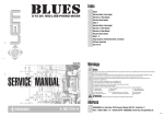
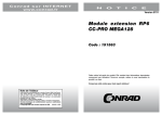
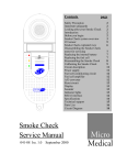
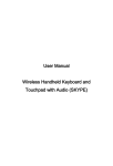
EduKitBeta User’s manual Educational board for MU Alpha / MU Beta and Microchip PIC microcontrollers with DIL18 package Page 1 / 8 CONTENTS EduKitBeta 3 Equipment description The board contains following peripherals: 3 3 Pin connection table for EdukitBeta PORTA PORTB 4 4 4 Power supply 4 Peripheral description LED diode LED display Pushbuttons (BT1 .. BT3) Buzzer EEPROM memory (I2C, ADDR0) Thermo sensor (I2C TEMP, ADDR1) RS-232 interface (COM) DIP switches 4 4 5 5 5 5 5 5 5 EduKitBeta – schematics 6 EduKitBeta – board layout 7 Connector to MU Beta 8 Expansion connector 8 Recommended add-ons 8 Further information 8 Contact to manufacturer 8 Page 2 / 8 EduKitBeta Is an educational board – designed as an add-on to MU Beta emulator by ASIX s.r.o. It is suitable especially for debugging of applications with PIC16F627 and PIC16F628 microcontrollers but also with PIC16C710, PIC16C711 and others. EduKitBeta together with MU Beta emulator is advisable for both beginers who would like to learn to work with PIC microcontrollers and advanced developers who need to quicky and easily check functionality of a program. Equipment description EduKitBeta is mainly targeted to be used as an add-on to MU Beta emulator by ASIX s.r.o. It is also possible to use it with MU Alpha but in such case it is not possible to take advantage of some of the peripherals though. For example it does not make any sense to set analog voltage at PIC16F84 inputs. The board contains following peripherals: 4 potentiometers connected to analog inputs 4-digit 7-segment LED display (3-wire controlled) Application LED 3 pushbuttons (including 1 reset button) I2C serial EEPROM in a socket (24LC01) I2C thermosensor RS232 receiver/transmitter Buzzer (connected to PWM output) DIP switches for disconnecting of the peripheals Power supply circuitry, +5 V voltage regulator Page 3 / 8 Pin connection table for EdukitBeta PORTA Port A bit 0 bit 1 bit 2 bit 3 bit 4 bit 5 bit 6 bit 7 Type analog analog analog analog input output input input input input input Function connected to potentiometer 1 connected to potentiometer 2 connected to potentiometer 3 connected to potentiometer 4 state of pushbutton BT3 - log.0 represents button pressed log.0 lights red LED external reset (-MCLR) not connected not connected PORTB Port B bit 0 bit 1 bit 2 bit 3 bit 4 Typ output input output output output bit 5 bit 6 input/output output bit 7 input output Funkce I2C clock UART receiver (RX) UART transmitter (TX) buzzer clock signal for LED display shift register; also used as display enable signal (1=enable - display is on, 0=disable display is off) I2C data display shift register strobe (1 = overwrite display contents, 0 = no change) state of pushbutton BT2 - log.0 represents button pressed display shift register data Note: If the on-board peripherals are disconnected using DIP switches DISPSW1 or DISPSW2 it is possible to connect user peripherals. Power supply Power supply with following parameters may be used: DC voltage of 8 to 20 V, 100 mA current. Recommended AC/DC adaptor is MW903GS (9 V/300 mA), which can be ordered separately. Peripheral description LED diode Red LED diode can be turned on by setting bit 4 of port A as output and writing log.0 to it. Writing log.1 turns the LED off. Page 4 / 8 LED display The display is using 7-segment LED devices. The display is static, the data is first transferred to shift register (4 x 74HC4094) and then using STROBE signal (port B, bit 6) written to outputs. Enable signal of the display is shared with clock signal (port B, bit 4) and thus it is necessary to turn the display on by setting the clock signal to log.1 after data is transferred to shift register. Pushbuttons (BT1 .. BT3) When a button is pressed a log.0 appears at corresponding pin. To read the state of a button the pin must be configured as an input. Buzzer Buzzer is connected to pin 3 of port B. Because the buzzer acts as a capacitor, it is possible to use pin 3 of port B for a user peripheral. EEPROM memory (I2C, ADDR0) There is 24LC01B memory in a socket communicating with the microcontroller over I2C bus. The device address is hardwired to 0. Thermo sensor (I2C TEMP, ADDR1) The board is equipped with intelligent thermosensor TCN75-5.0 by Microchip which can be interfaced using I2C bus. The device address is hardwired to 1. RS-232 interface (COM) The board contains a voltage converter between TTL and RS-232 (+12 V a -12 V) levels which is connected to UART of the microcontroller (pins B1 and B2). Jumper JP1 may be used to short-circuit pins 7 (RTS) and 8 (CTS) on 9-pin Sub-D connector, similarly JP2 interconnects pins 4 (DTR) and 6 (DSR). DIP switches Most of the peripherals on EduKitBeta board can be disconnected from the microcontroller using DIP switches. This feature is convenient if the user needs to connect own devices. If an on-board peripheral is to be used, please remember to turn corresponding DIP switch to ON position. Page 5 / 8 EduKitBeta – schematics Page 6 / 8 EduKitBeta – board layout Page 7 / 8 Connector to MU Beta Connector to MU Beta (J2) has 20 pins. First 2 pins are unused, while pins 1 to 18 connect to microcontroller signals: unused RA2 RA3 RA4 RA5/-MCLR GND RB0 RB1 RB2 RB3 x 1 2 3 4 5 6 7 8 9 x 18 17 16 15 14 13 12 11 10 unused RA1 RA0 RA7/OSC1 RA6/OSC2 +5V RB7 RB6 RB5 RB4 Expansion connector Expansion connector (J3) contains all microcontroller signals. The pin layout corresponds with the pinout of the microcontroller: RA2 RA3 RA4 RA5/-MCLR GND RB0 RB1 RB2 RB3 1 2 3 4 5 6 7 8 9 18 17 16 15 14 13 12 11 10 RA1 RA0 RA7/OSC1 RA6/OSC2 +5V RB7 RB6 RB5 RB4 Recommended add-ons MW903GS - power supply adaptor, 9 V/300 mA Further information [1] http://www.pic-tools.com [2] http://www.microchip.com Contact to manufacturer Address: Phone: Fax: E-Mail: WWW: ASIX s.r.o., Staropramenna 4, 150 00 Prague, Czech Republic +420-257 312 378 +420-257 329 116 [email protected] [email protected] www.pic-tools.com MANEKB-A Copyright © 1991-2003 ASIX s.r.o. All trademarks used in this document are properties of their respective owners. This information is provided in the hope that it will be useful, but without any warranty. We disclaim any liability for the accuracy of this information. We are not responsible for the contents of web pages referenced by this document. Page 8 / 8