1
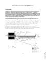
(b)
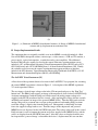
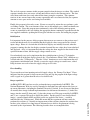
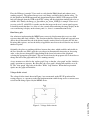
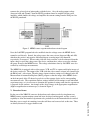
Figure 1: (a) Schematic of MEMS electrothermal actuator, (b) Image of MEMS electrothermal
actuator and tip displacement measurement scale
II. Project Implementation Details
The equipment that was originally available to us in the MEMS research lab included: a Karl
Suss model PM-4 microprobe station, a microscope, a video camera, a VCR and TV monitor, a
power supply, a pair of microprobes, a switch box and a power amplifier. The additional
hardware that had to be acquired to develop the remote laboratory experimentation system
included: a PC, an Educational Laboratory Virtual Instrumentation Suite (ELVIS) unit, a PCI6251 DAQ board, and a PCI-1405 IMAQ board - all from National Instruments (NI). Finally,
the software needed to create the remote experimentation program and the user interface
included: the NI Laboratory Virtual Instrument Engineering Workbench (LabVIEW) v8.5, NI
Measurement and Automation Explorer (MAX), and NI IMAQ.
The LabVIEW Virtual Instrument (VI)
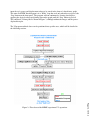
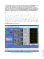
A flow chart of the operations that need to occur in the LabVIEW VI (or program) for executing
the remote MEMS experiment is shown in Figure 2. A description of this MEMS experiment
VI’s main operations follows.
Page 14.1019.3
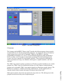
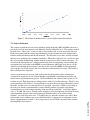
The user inputs a desired input voltage value in the VI front panel and presses the “Run Test”
button icon. The IMAQ card captures an image of the unpowered device before LabVIEW DAQ
Assistant communicates with the DAQ card, which creates the analog output voltage to be
supplied to the ELVIS protoboard for five seconds. After applying this voltage for four seconds,
an IMAQ card captures an image of the powered MEMS device. Then the DAQ card reads the
analog voltage across a current-sense resistor on the protoboard, and another DAQ Assistant
reads that voltage’s digital value from the DAQ card. Subsequently, a third DAQ Assistant
forces the supplied voltage back to zero. Then the images of the unpowered and powered
MEMS device are displayed on the LabVIEW front panel. The voltage value read by the second
DAQ assistant is used to compute the current and power supplied to the MEMS device, and the
values are displayed on the LabVIEW front panel. After the values are displayed and the user
has inspected the ‘powered image’ to determine the device’s displacement, the user can then