1
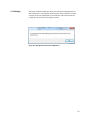
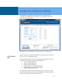
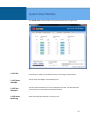
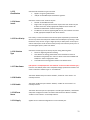
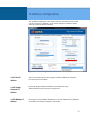
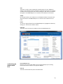
User’s Manual MaxiiPowerTM Vi2208A & Vi2216A High Powered PoE Midspans UTP MaxiiPowerTM Vi2508 & Vi2516 High Powered Midspans UTP Extenders MaxiiPowerTM Vi2608 & Vi2616 High Powered Midspans Ethernet to Coax Extender Version 1.2 Updated 10/07/2015 2013 Vigitron, Inc. All rights reserved. All brand and product names are trademarks or registered trademarks of their respective companies. Contents Vi22A/25/26 Series Ethernet Midspan Installation Manual .................................................................................... 6 System Requirements .............................................................................................................................................. 8 1.1 Overview ....................................................................................................................................................... 8 1.2 Drawings ....................................................................................................................................................... 8 Hardware Specifications ........................................................................................................................................ 14 1.3 Electrical...................................................................................................................................................... 14 1.4 Environmental ............................................................................................................................................. 14 1.5 Mechanical .................................................................................................................................................. 14 1.6 Regulatory Certifications............................................................................................................................. 15 1.7 Included Accessories ................................................................................................................................... 15 1.8 Hardware Setup .......................................................................................................................................... 15 1.9 LED Diagnostics ........................................................................................................................................... 15 1.10 GUI System Requirements ........................................................................................................................ 15 GUI (Graphical User Interface) Installation Procedure .......................................................................................... 16 Midspan Default Network ..................................................................................................................................... 21 Username and Password ....................................................................................................................................... 21 Firmware Window ................................................................................................................................................. 21 System Configuration Window .............................................................................................................................. 23 1.11.1 Power Management .............................................................................................................................. 23 1.11.2 ILIM/ICUT Configuration ........................................................................................................................ 24 1.11.3 System Configuration ............................................................................................................................. 24 1.11.4 Chip ID.................................................................................................................................................... 24 1.11.5 SW Version ............................................................................................................................................. 24 1.11.6 Max Ports ............................................................................................................................................... 25 1.11.7 Power Available ..................................................................................................................................... 25 1.11.8 Power Allocated ..................................................................................................................................... 25 1.12.1 Commands ............................................................................................................................................. 25 1.12.2 Query ..................................................................................................................................................... 25 1.12.3 Apply ...................................................................................................................................................... 25 1.12.4 Delayed Power up .................................................................................................................................. 25 1.12.5 Port ........................................................................................................................................................ 25 1.12.6 0-240 ...................................................................................................................................................... 25 1.12.7 Enable All Ports ...................................................................................................................................... 25 2 1.12.8 Disable All Ports ..................................................................................................................................... 25 1.12.9 Set delay time for all ports ..................................................................................................................... 25 1.12.10 Apply .................................................................................................................................................... 26 Multiple Port Configuration Window .................................................................................................................... 27 1.13.1 Detection Type ....................................................................................................................................... 27 1.13.2 Classification .......................................................................................................................................... 28 1.13.3 Violation Type ........................................................................................................................................ 28 1.13.4 Max Power ............................................................................................................................................. 28 1.13.5 Power Inrush Control ............................................................................................................................. 28 1.13.6 Disable ................................................................................................................................................... 28 1.13.7 Enable .................................................................................................................................................... 28 1.13.8 Force Power ........................................................................................................................................... 28 1.13.9 Select All ................................................................................................................................................ 28 1.13.10 Apply .................................................................................................................................................... 28 System View Window ............................................................................................................................................ 29 1.14.1 Poll ......................................................................................................................................................... 29 1.14.2 Power Available ..................................................................................................................................... 29 1.14.3 Port Allocated ........................................................................................................................................ 29 1.14.4 Power Delivering .................................................................................................................................... 29 1.14.5 Port ........................................................................................................................................................ 30 1.14.6 Port Status ............................................................................................................................................. 30 1.14.7 Port Power ............................................................................................................................................. 30 Port Configuration Window ................................................................................................................................... 31 Port Configuration ............................................................................................................................................ 31 1.15.1 Port ........................................................................................................................................................ 31 1.15.2 Detection Type ....................................................................................................................................... 31 1.15.3 Classification .......................................................................................................................................... 32 1.15.4 Power Inrush .......................................................................................................................................... 32 1.15.5 Port Priority ............................................................................................................................................ 32 1.15.6 Violation Type ........................................................................................................................................ 32 1.15.7 Max Power ............................................................................................................................................. 32 1.15.8 Disable ................................................................................................................................................... 32 1.15.9 Enable .................................................................................................................................................... 32 1.15.10 Force Power ......................................................................................................................................... 32 1.15.11 Apply .................................................................................................................................................... 32 Port Status ........................................................................................................................................................ 33 3 1.16.1 Status ..................................................................................................................................................... 33 1.16.2 Class/Error Value .................................................................................................................................... 33 1.16.3 Remote PD Type ..................................................................................................................................... 33 1.16.4 Voltage ................................................................................................................................................... 33 1.16.5 Current ................................................................................................................................................... 33 1.16.6 Power ..................................................................................................................................................... 33 1.16.7 Temperature .......................................................................................................................................... 33 Statistics ............................................................................................................................................................ 34 1.17.1 Overload Counter .................................................................................................................................. 34 1.17.2 Short Counter......................................................................................................................................... 34 1.17.3 Power Denied Counter ........................................................................................................................... 34 1.17.4 Invalid Detection Counter ...................................................................................................................... 34 1.17.5 Reset Statistics ....................................................................................................................................... 34 IP Address Configuration ....................................................................................................................................... 35 1.18.1 Host IP Address ...................................................................................................................................... 35 1.18.2 Display Computer IP Address ................................................................................................................. 35 1.18.3 Midspan IP Address ............................................................................................................................... 35 1.18.4 Find All Midspan IP Addresses ............................................................................................................... 36 1.18.5 Midspan IP Address Programmer .......................................................................................................... 36 1.18.6 Program New Midspan IP Address......................................................................................................... 36 1.18.7 GUI IP Address List ................................................................................................................................. 36 1.18.8 Add IP Address & Description ................................................................................................................ 36 1.18.9 Delete Selected IP Address .................................................................................................................... 36 SNMP (Simple Network Management Protocol) ................................................................................................... 37 1.19.1 How to Receive SNMP Messages ........................................................................................................... 37 1.19.2 Creating a List of Midspans to be Monitored with SNMP ...................................................................... 38 1.19.3 Setting Up SNMP Enabled Ports............................................................................................................. 39 1.19.4 Saving and Loading the SNMP Configuration ........................................................................................ 40 1.19.5 Miscellaneous Controls .......................................................................................................................... 40 1.19.6 Audible Warning .................................................................................................................................... 40 1.19.7 Visual Warning ....................................................................................................................................... 41 1.19.8 Enable Tool Tips ..................................................................................................................................... 41 1.19.9 Auto Save on Start SNMP ....................................................................................................................... 41 1.19.10 SNMP Activated/Not Activated Label .................................................................................................. 41 1.19.11 SNMP Message Description ................................................................................................................. 42 1.19.12 Fault Code Description ......................................................................................................................... 42 4 Appendix A ............................................................................................................................................................ 44 Software Acceptance Terms and Conditions .................................................................................................... 44 Warranty ................................................................................................................................................................ 46 Table of Figures Figure 1: Vi2216a Front View ...................................................................................................................................8 Figure 2: Vi2208a Front View ...................................................................................................................................8 Figure 3: Vi2208a/Vi2216a Rear View ......................................................................................................................8 Figure 4: Vi2216 Application Drawing ......................................................................................................................9 Figure 5: Vi2508/Vi2508s Front View .......................................................................................................................9 Figure 6: Vi2508/Vi2508s Front View .......................................................................................................................9 Figure 7: Redundant Power Supply Connector Pin-Out............................................................................................9 Figure 8: Vi2508s/Vi2516s Rear View .....................................................................................................................10 Figure 9: Vi2508/Vi2516 Rear View ........................................................................................................................10 Figure 10: Vi2516 Application Drawing ..................................................................................................................10 Figure 11: Vi2616/Vi2616s Front View ...................................................................................................................10 Figure 12: Vi2608/Vi2608s Front View ...................................................................................................................11 Figure 13: Vi2608s/Vi2616s Rear View ...................................................................................................................11 Figure 14: Vi2608/Vi2616 Rear View ......................................................................................................................11 Figure 15: Vi2616 Application Drawing ..................................................................................................................11 Figure 16: Firmware Window ................................................................................................................................22 Figure 17: System Configuration Window .............................................................................................................23 Figure 18: Message Box to Save the Configuration ...............................................................................................26 Figure 19: System View Window ...........................................................................................................................27 Figure 20: Multiple Port Configuration Window ....................................................................................................29 Figure 21: Port Configuration .................................................................................................................................31 Figure 22: IP Address Configuration .......................................................................................................................35 5 Vi22A/25/26 Series Ethernet Midspan Installation Manual Read and keep these instructions. Heed all warnings. Follow all instructions. Do not use this apparatus near water. Clean only with a dry cloth. Install in accordance with the manufacturer’s instructions. This installation should be made by a qualified service person and should conform to all local codes. DO NOT bundle UTP or UTP signals in the same conduit as high-voltage wiring. To reduce the risk of fire or electrical shock, do not expose these products to rain, moisture, dripping or splashing. No objects filled with liquids, such as vases, shall be placed on Vigitron equipment. DO NOT install the unit in a place where the operating ambient temperature exceeds 75°C. Make sure that the external power supply output voltage is in the recommended range. Do not install near any heat sources such as radiators, heat registers, stoves or other apparatus (including DVRs) that produce heat. Protect the power cord from being walked on or pinched particularly at power source, convenience receptacles, and the point where they exit from the apparatus. Only use attachments/accessories specified by the manufacturer. Unplug this apparatus during lightning storms or when unused for long periods of time. Refer all servicing to qualified service personnel. Servicing is required when the apparatus has been damaged in any way, such as when a power supply cord or plug is damaged, liquid has been spilled, objects have fallen inside the apparatus, the apparatus has been exposed to rain or moisture, does not operate normally, or has been dropped. The main plug is used as the disconnect device and shall remain readily operable. 6 7 System Requirements 1.1 Overview The MaxiiPower™ Models Vi2208A/Vi2216A are 8 and 16-port High Powered PoE Midspans. Models Vi2508/Vi2516 and Vi2608/2616 are 8 and 16-port High Powered PoE Extended Midspans. They meet IEEE 802.3af, IEEE 802.3at standards, and Hi PoE application. The MaxiiPower™ Vi22A/Vi25 series can deliver up to 37W per port simultaneously on all ports without requiring power sharing. Ports 1-4 are Hi PoE ports and deliver up to 74W per port with the exception of the Vi2600 series. The PoE functions can be set up with Windows GUI, or use the default plug and play option. The Midspan GUI is an easy and powerful tool that runs on the host PC and provides configuration power supervision, monitoring, and diagnostics of all ports through either Ethernet or a USB port. The MaxiiPower™ Midspans are 1U height and can be easily installed in 19” racks. They are ideal for a wide range of CCTV or IT applications that require high power, such as IP cameras, wireless access points, or VoIP to be connected to a central LAN switching fabric with ease. The Midspans and Midspan extender combinations can be set up and accessed either by direct connection via USB or over a network. Client software allows enterprise level connections to all Vi22, Vi25, and Vi26 series operating on the network. SNMP reports out several trouble areas in real time via the operator programming to apply naming conventions to both units and individual ports. 1.2 Drawings Figure 1: Vi2216A Front View Figure 2: Vi2208A Front View Figure 3: Vi2208A/Vi2216A Rear View 8 Figure 4: Vi2216 Application Drawing Figure 5: Vi2516/Vi2516S Front View Figure 6: Vi2508/Vi2508S front view Figure 7: Redundant Power Supply Connector Pin-Out 9 Figure 8: Vi2508S/Vi2516S Rear View Figure 9: Vi2508/Vi2516 Rear View Figure 10: Vi2516 Application Drawing Figure 11: Vi2616/Vi2616S(L) Front View 10 Figure 12: Vi2608/Vi2608S Front View Figure 13: Vi2608S/Vi2616S(L) Rear View Figure 14: Vi2608/Vi2616 Rear View Figure 15: Vi2616 Application Drawing Note: The Vi2616L and Vi2616SL models are only compatible with Vi2400AL/2401AL Extenders. Models ending in the letter "L" operate at 100Mb/s only. 11 Connect the cables from the camera or other powered device to the upper connectors. When using the Vi22 series, the cable must be a Cat5/6 with a maximum length of 100 m. Extended Midspans must be used with single port extenders on the camera side. Models Vi2300A and 2301A can be used with the Vi25xx series Midspans while models Vi2400A and Vi2401A are compatible with the Vi26xx series. Connect the RJ45 cables from the Ethernet switch to the Standard Ethernet ports (Lower row) of Midspan/Midspan Extender. Connect the extended distance UTP or coax cables to the upper connectors of the extended Midspan. LED Name Color Status Function PoE Green Off On Flashing No power provided Delivering power Fault condition Vi22xx Series 12 LED Name Color PoE Green 10/100 Base T Link Traffic Vi25xx Series Off On Flashing Extended Ethernet Ports (Upper row) Green On Orange On Standard Ethernet Ports (Lower row) Orange On Green Flashing LED Name Color PoE Orange 10/100 Base T Link Traffic Vi26xx Series Status Status Off On Flashing Extended Ethernet Ports (Upper row) Green On Yellow On Standard Ethernet Ports (Lower row) Orange On Green Flashing Function No power provided Delivering power Fault condition Connected @ 10 Mb/s Connected @ 100Mb/s Connection is good Data is being sent Function No power provided Delivering power Fault condition Connected @ 10 Mb/s Connected @ 100Mb/s Connection is good Data is being sent 13 Hardware Specifications 1.3 Electrical Ethernet Interface Standard 10/100/1000BaseT UTP Category-5 (or higher) AC Input 57 VDC, 74W max. per port on ports 1-4 (Vi22/Vi25 series) 57 VDC, 37W max. per port on ports 5-16 (Vi22/Vi25 series) 57 VDC, 37W max. per port on ports 1-16 (Vi26 series) 300W max. aggregated (8 port Midspans) 600W max. aggregated (16 port Midspans) 110 -240 V AC, 50-60 Hz, 6.5 A max. Output Status LED Green LED Output Power Connectors Setup Port 1.4 Environmental 1.5 Mechanical Ethernet Input Interface: Shielded RJ-45 Ethernet Output Interface: Shielded RJ-45 AC Power: IEC380-8 inlet Redundant power: 5-pin circular connector (Vi25xxS and Vi26xxS) Redundant power connector pin-out (1&2 = Negative, Pin 3 = Chassis ground, Pins 4&5 = Positive) RJ45 Ethernet, USB with Windows GUI Humidity 0 to 90%, non-condensing Temperature Operating: -10°C to +50°C Storage: -30°C to +70°C Dimensions 1.75x17x12 in, 4.3x43x30.5 cm (HxWxL) Weight Material 8 Lbs., 3.6 Kg (Vi2608) 11 Lbs., 5 Kg (Vi2616) Sheet metal and extruded Aluminum Operation 0°C to +50°C Storage -30°C to +70°C 14 1.6 Regulatory Certifications CE, RoHS, WEEE, UL, cUL 1.7 Included Accessories Accessories: 1.8 Hardware Setup Please follow the following steps to install the Midspan: Mounting brackets for front, rear, or wall installations Rubber feet for desk applications Molded IEC 7 ft. (200 cm) power cord 8 or 16 Cat5 cables with RJ45 connectors (Vi22/25 series) 1m 5 conductor with circular 5-pin connectors on both ends (Vi25xxS and Vi26xxS) *Specifications subject to change without notice. Connect an AC power cable to the Midspan. Use either an Ethernet or a USB cable to connect the Midspan to the Host PC. Connect a PoE powered device (PD) to one of the Midspans ports using a Cat5/6 or coax cable, depending on your model. Extended Midspans must use an extender unit before the PD. UTP Midspans are compatible with models Vi2300A and Vi2301A, while coax Midspans use models Vi2400A and Vi2401A. The Midspans are set to “Auto” mode by the factory. In this mode, the Midspan works as a plug and play device. It automatically detects the PD and provides requested PoE power. To use the GUI (Graphical User Interface), a computer can connect to the Midspan through either a USB cable or through a network connection. When using a USB cable, the GUI should be started after the computer is connected to the Midspan. 1.9 LED Diagnostics Each port is equipped with an LED that provides port status as the following: 1.10 GUI System Requirements Recommended Operating system: Windows XP, Vista, Windows7 and Windows 8. It requires Microsoft .NET Framework 4 installed on the host computer. Off: The port is off and no Power is provided. On: PoE power is on and is powering a valid PD. Slow Blinking: The port does not have enough power for the load. Fast Blinking: It warns that the connected PD is shorted or over current. Port Communication: Ethernet or USB port. 15 GUI (Graphical User Interface) Installation Procedure Important Note: By running the GUI software, you are accepting all terms and conditions of using this software as noted in Appendix A. The following section will guide you how to use the High Power PoE Midspan GUI and connecting the host computer to the Midspan through a USB cable. Your windows may not update the USB port driver automatically. You may need to update the driver manually as followings: A. Window XP: Go to System property->Hardware->Device manager->USB Serial converter and update driver. B. Window Vista, Window 7, and Windows 8: Go to System property->Device manager->USB Serial converter and update driver. A USB cable is provided to connect the computer to the Midspan. Click on the IP Address Configuration tab. After connecting the Midspan to the host computer and the USB driver is installed, run the GUI executable file (xxxxx.exe) on the PC. 16 Under “Connection Method”, click the down arrow in the drop down box. The GUI will display all the available COM ports present on the PC. The example below shows three ports available: Com1, Com3, and Com50. If you are not sure which Com port to select, you can go to the “Device Manager” window of your computer. Click the “Ports” icon and a list of ports will be displayed along with a brief description. The following example shows COM 50 as being a USB serial port. The Midspan is connected to this port. Now you can go back and select the appropriate USB port to use to connect to the Midspan. On the lower portion of the GUI, be sure that the USB button to the left of port selection is clicked. Then, click the “Connect” button. This should connect your PC to the Midspan and the “Status” at the bottom of the window should display “Connected”. 17 Common issues that prevent a successful connection are: not having the USB driver installed, incorrect port selection, or not powering up the Midspan. 18 Connecting Through an Ethernet Cable Open the GUI or if not already installed, run the GUI executable file (xxxxx.exe) on the PC. Step 1 – Acquire your network information. Log into the GUI by entering the username and password. If this is the first time the GUI is opened, a username and password must be inputted. Go to the “IP Address Configuration” tab. Click on “Display Computer IP Address”. The example below shows an IP Address of 192.168.2.35 for the computer. Note: Some computers will have more than one IP Address. Be sure to use the IP address that will be used to connect to the Midspan. Step 2 – Locate any Midspans on your network. Click on “Find all Midspan IP Addresses”. A list of Midspan IP Addresses will appear in the window. Select the Midspan address to be reprogrammed by clicking on the IP Address. If reprogramming the Midspan IP Address is not necessary, skip to Step 4. Step 3 – Program Midspan to operate on your network. Selecting the Midspan to be programmed in step 2 will place the IP Address into the box labeled “Current IP Address”. If changing the Midspan IP Address is necessary, input the new values for the IP Address, Default Gateway, and Subnet Mask. Then, press the “Program New IP Address”. The example below shows the IP Address being changed from 192.168.2.107 to 192.168.2.117. 19 Step 4 – Add the new Midspan IP Address to the GUI. Once programmed, the new IP Address will appear in the four boxes located in the “GUI IP ADDRESS List”. If you did not reprogram the IP address, you will need to manually enter the address. You may also add an optional description to the IP Address. For example: South building. Then, click on “Add IP Address + Description”. Step 5 – Connect to Midspan. To connect to the Midspan, click on the down arrow under “Midspan IP Address”. Click on the appropriate Midspan address. Verify “Ethernet” is selected under “Connection Method”. Click “Connect” under “Midspan Connection”. When the connection is successful, the gray box will display the word “Connected”. Common reasons that prevent a successful connection are no power to the Midspan or incompatible network IP Addresses between the host computer and the Midspan. Be sure the first three numbers of the computer and Midspan IP Addresses are the same. The fourth number must be different. 20 Midspan Default Network IP Address = 192.168.2.107 Subnet Mask = 255.255.255.0 Default Gateway = 192.168.2.1 Username and Password When the GUI is first installed, a Username and Password must be entered before clicking the “Submit” button. The login information is chosen by the user and must be between 4 and 12 characters long. To change the username and password, you must login first. The “Submit” button will now read “Change Username and Password”. At this point, you can enter in a new user name and password, and then click “Change Username and Password” to update the login information. Firmware Window Warning: Upgrading firmware is not part of the normal operating procedure. It should only be performed at the recommendation of the manufacturer by a skilled personnel. Improper upgrading will affect equipment performance and may result in rendering the equipment inoperative. The Midspan GUI requires Microsoft .NET Framework 4 installed on the host computer. If you are running the GUI for the first time on a host computer with Windows XP, you may need to visit the Microsoft website to download and install Microsoft .NET Framework 4. 21 Figure 16: Firmware Window Firmware File: A new unit has all the necessary programing and does not need this step. To change the firmware of the Midspan, you will need a file containing the new firmware. The location of the file containing the new firmware is displayed in this box. Browse: The File browse dialog box will be opened to select the firmware file to be used. Download: The image file that was selected using the “Load” command will be downloaded to the Midspan and replaced the current firmware. Clear Image: Caution: only click this button when prompted to do so. When connected to a Midspan, this button will delete the existing firmware and the Midspan will not operate without new firmware being loaded. Save Config: This button saves the current running configuration to the internal memory of the Midspan. Saving the Configuration will prevent the loss of the individual port and power settings selected by the user. The Midspan can be switched off and on without losing the configuration. Command Progress: This bar will display the progress of commands. 22 System Configuration Window The “System Configuration” window provides access to setting global configurations and status view of major parameters. Figure 17: System Configuration Window 1.11.1 Power Management These settings will help you to match the power requirements of your system to the power output of the Midspan. Power Management can be used in the following modes: None: Indicates Power Management will not be performed by the firmware. User needs to power up the ports manually. Static /w Priority: Power is budgeted statically based on selected violation type, located under the “Multiple Port Configuration” or “Port Configuration” tabs. o If violation type is “Class Based”, then maximum permissible power for that class is budgeted. o If violation type is “User Defined”, then the configured userdefined limit is budgeted. o If violation type is “None”, then budgeted power is based on port mode. 23 For Normal Mode, the power budgeted is 16.2W: For High Power Mode (802.3at-Class 4) the power budgeted is based on ILIM/ICUT selected value. o For ILIM/ICUT – 504/465 mA, the power budgeted is 22.5W. o For ILIM/ICUT – 563/545 mA, the power budgeted is 26.5W. o For ILIM/ICUT – 850/625 mA, the power budgeted is 31.6W. o For ILIM/ICUT – 850/725 mA, the power budgeted is 37.0W. These limits will help to provide the necessary power for your system and prevents run away shorting and potential damage from occurring. Static /wo Priority: Same as above except that port priority of the port is ignored. Static /wo Priority: Power is budgeted statically based on selected violation type. o If violation type is “Class Based”, then maximum permissible power for that class is budgeted. o If violation type is “User Defined”, then the configured userdefined limit is budgeted. o If violation type is “None”, then budgeted power is based on port mode. For Normal Mode, the power budgeted is 16.2W: For High Power Mode, the power budgeted is based on ILIM/ICUT selected value. For ILIM/ICUT – 504/465 mA, the power budgeted is 22.5W. For ILIM/ICUT – 563/545 mA, the power budgeted is 26.5W. For ILIM/ICUT – 850/625 mA, the power budgeted is 31.6W. For ILIM/ICUT – 850/725 mA, the power budgeted is 37.0W. Dynamic /w Priority: The power is budgeted based on the load and priority of the port. Dynamic /wo Priority: The power is budgeted based on the Load. 1.11.2 ILIM/ICUT Configuration 1.11.3 System Configuration 1.11.4 Chip ID 1.11.5 SW Version Set the Current Limit and Current Cut Limit (ILIM/ICUT). This section displays the status of information about the Midspan. This shows the current PSE control Chip Revision. This shows the current running firmware version. 24 1.11.6 Max Ports This shows the maximum number of Midspan ports detected by the software. 1.11.7 Power Available This shows the total available power for the Midspan. 1.11.8 Power Allocated This shows the total power allocated by the system. Power allocated varies based on the power management mode selected. 1.12.1 Commands 1.12.2 Query Click the “Query” button to update the status fields. 1.12.3 Apply Click the “Apply” button to configure the system with the inputted values. 1.12.4 Delayed Power up The delayed Power up section gives the user the ability to prevent all ports from turning on at the same time following a power failure. This will prevent any large current surges on the AC power that supplies the Midspan. Each port can be programmed with a delay time starting from the point the Midspan finishes booting up and ending with the port delivering PoE power. This delay can be anywhere from 0 to 240 seconds. During this delay time the PoE LED’s with will flash on any ports that have a valid load attached. This is to show that the Midspan port(s) are in delay mode and will be powered once the delay time has expired. 1.12.5 Port Signifies the port number that corresponds to the controls. 1.12.6 0-240 The port delay can be enabled or disabled according to the selection from the drop down menu. When “Disabled” is selected “0” will always be displayed as the delay time. If “Enabled” is selected, the delay time can be set. Zero will act the same as disabling the port. Selecting 1-240 will set a delay period. Clicking the “Query” button will display the individual port time delay that is currently programmed in the Midspan, only if “Enabled” is selected. 1.12.7 Enable All Ports When clicked, this button will set all ports to “Enabled”. 1.12.8 Disable All Ports Clicking this button will disable all ports and set the delay time to 0. 1.12.9 Set delay time for all ports By changing this setting, the value will be applied to all ports. 25 1.12.10 Apply This button should be clicked after all the ports have been configured with the desired delay time. A message box will then appear as shown below. It is always necessary to save the configuration in the “Firmware” tab to ensure that your changes are not lost from an interruption in power. Figure 18: Message Box to Save the Configuration 26 Multiple Port Configuration Window The “Multiple Port Configuration” window enables a way to apply the same configuration to multiple ports in a single screen. This is the fastest way to apply similar changes to multiple ports. Figure 19: Multiple Port Configuration Window * Changes are communicated to unit however this page will not reflect status. 1.13.1 Detection Type Different PoE devices may respond to differences in detection pulses. If your device does not turn on, try changing this setting. Choose the detection type to be used for selected ports matching it to the camera requirements. Most cameras will work in the default position. “None” for bypassing detection. “2-point” for 2-point detection. “4-point” for 4-point detection. “4-point+legacy” for 4-point followed by legacy. “2-point+legacy” for 2-point followed by legacy. “Legacy” for legacy detection only. This option will be considered the next time a “detection" is performed on a port. This will not affect ports currently in a power delivering state. To apply a change of the detection type, disable, and then enable the port. 27 1.13.2 Classification Choose the classification type for selected ports: “Bypass” for ignoring classification. “.3AF/AT” for IEEE 802.3af/at classification signature. 1.13.3 Violation Type Choose the violation type for selected ports during delivering state: “None” for bypassing violation checking. “Class Based” for limiting power based on the classification results. If classification is bypassed, then “Class-0” will be used in Normal Mode and “ILIM/ICUT” values in high power mode. “User Defined” for limiting power based on user defined value. 1.13.4 Max Power Choose the user defined power value. This value is used if the “Violation Type” is “User Defined”. Acceptable wattage inputted is 0-51 Watts. 1.13.5 Power Inrush Control Choose the “Power Inrush Control” mode of selected port: “Normal” for IEEE 802.3af mode. “High Inrush” for Legacy devices which require more than 15.4W. For port to deliver more than 15.4W, appropriate ILIM/ICUT value needs to be selected and classification needs to be bypassed. “Pre 802.3at” for devices supporting 802.3at. Use this mode for delivering more than 15.4W, appropriate ILIM/ICUT value should be selected. 1.13.6 Disable Check this box to disable selected ports. Check boxes “Disable”, “Enable” & “Force Power” are mutually exclusive. 1.13.7 Enable Checking this box will enable selected ports. 1.13.8 Force Power Check this box to force selected the port to “Power On”. This will bypass detection, classification and power management steps and no violation will be honored. 1.13.9 Select All Check “Select All” to select all ports. Otherwise, each port number must be individually selected. 1.13.10 Apply This button must be clicked to load the user selected configuration on to the selected ports. 28 System View Window The “System View” window enables viewing status of all ports on a single screen. Figure 20: System View Window 1.14.1 Poll If the Poll box is checked, it will enable continuous refreshing of the parameters. 1.14.2 Power Available This box shows the Midspan total available power. 1.14.3 Port Allocated The total power allocated by the system is displayed in this box. The allocated power varies based on the selected Power Management Mode. 1.14.4 Power Delivering Shows the total power delivered on all active ports. 29 1.14.5 Port 1.14.6 Port Status 1.14.7 Port Power This displays the port numbers. This shows the port status. The status is color coded as following for easy identification: Green = Delivering Blue = Searching Gray = Disabled Yellow = Requesting Power Orange = Test mode Red = Fault The power currently being delivered by the port is displayed. If the port is not in “Delivering” mode, it will show “N/A”. 30 Port Configuration Window The “Port Configuration” window enables the ability to configure a single port and view its status. Figure 21: Port Configuration Port Configuration 1.15.1 Port Select the port number to be changed or status viewed. 1.15.2 Detection Type Selects the PD detection type to be used: “None” for bypassing detection. “2-point” for 2-point detection. “4-point” for 4-point detection. “4-point+legacy” for 4-point followed by legacy. “2-point+legacy” for 2-point followed by legacy. “Legacy” for legacy detection only. The “Legacy” option will be considered the next time a “detection" is performed on a port. This will not affect ports currently in a power delivering state. To apply a change of the detection type, disable and then enable the port. 31 1.15.3 Classification Selects the PD classification type to be used: “Bypass” for ignoring classification. “.3AF/AT” for IEEE 802.3af/at classification signature. 1.15.4 Power Inrush Selects the “Power Inrush” mode of the port: “Normal” for IEEE 802.3af mode. “High Inrush” for Legacy devices which require more than 15.4W. For port to deliver more than 15.4W, appropriate ILIM/ICUT value needs to be selected and classification needs to be bypassed. “Pre 802.3at” for devices supporting 802.3at. For port to deliver more than 15.4W, appropriate ILIM/ICUT value to be selected. 1.15.5 Port Priority Port Priority is used in situations where the total power requested by all connected devices may exceed the total power available from the Midspan. By entering a value between 0 and 3, the user can give a higher priority to deliver power to some ports and less critical ports can be set with a lower priority. Ports with the priority set to 3 have the highest priority and 0 is the lowest. 1.15.6 Violation Type Selects the violation type to be used by the port during delivering state: “None” for bypassing violation checking. “Class Based” for limiting power based on the classification results. If classification is bypassed, then “Class-0” will be used in Normal Mode and “ILIM/ICUT” values in High power mode. “User Defined” for limiting power based on user defined value. 1.15.7 Max Power (This option is not displayed until “User Defined” is selected under Violation Type.) Enter the user defined power value. Acceptable wattage inputted is 0-51 Watts. This value is used if the “Violation Type” is “User Defined”. 1.15.8 Disable This button disables the port. Buttons “Disable”, “Enable” & “Force Power” are mutually exclusive. 1.15.9 Enable This button enables the port. Buttons “Disable”, “Enable” & “Force Power” are mutually exclusive. 1.15.10 Force Power This button forces the port to output power. This will bypass detection, classification and power management checks. No violation will be honored. Buttons “Disable”, “Enable” & “Force Power” are mutually exclusive. 1.15.11 Apply Applies the user selected configuration on to the selected port. 32 Port Status Check to enable polling of port. Uncheck to disable polling. 1.16.1 Status This shows the port status. The status is color coded for easy identification. “Green” for delivering. “Blue” for searching. “Gray” for disabled. “Yellow” for Requesting Power “Orange” for Test mode. “Red” for Fault. 1.16.2 Class/Error Value This shows the class being detected in case of normal operation. Also, it shows the error value in case of a fault condition. 1.16.3 Remote PD Type This shows the type of PD (Powered device) detected by the Midspan. If there is no PD detected, the Midspan will not automatically apply power. 1.16.4 Voltage This shows the output voltage of the port. 1.16.5 Current This shows the current being delivered. 1.16.6 Power This shows the power being delivered 1.16.7 Temperature This shows the junction temperature of the controller chip of that specific port. 33 Statistics 1.17.1 Overload Counter This shows how many times the port has been in overload status. 1.17.2 Short Counter This shows how many times the port has been shorted. 1.17.3 Power Denied Counter This shows how many times the port has denied power to loads. 1.17.4 Invalid Detection Counter This shows how many times the port has detected an invalid load. 1.17.5 Reset Statistics This will reset all port statistics. 34 IP Address Configuration The “IP Address Configuration” tab is used to add a list of IP addresses that the GUI can use to connect to a Midspan. It is also used to change the IP Address, Default Gateway, and Subnet Mask of a Midspan. Figure 22: IP Address Configuration 1.18.1 Host IP Address This is used to determine the Host computer IP address. Note: Some computers have more than one IP Address. 1.18.2 Display Computer IP Address By clicking “Display Computer IP Address”, the GUI will show the IP address/addresses of the computer running the GUI. 1.18.3 Midspan IP Address By clicking on “Find all Midspan IP Addresses”, a list of IP addresses of any Midspans connected to the network will appear in the window. 35 1.18.4 Find All Midspan IP Addresses 1.18.5 Midspan IP Address Programmer This section is used to reprogram the network settings of a Midspan. This will reset all port statistics. 1.18.6 Program New Midspan IP Address The IP address, Default gateway and Subnet mask can be reprogrammed by inputting the data and then clicking on “Program Midspan IP Address”. 1.18.7 GUI IP Address List This section is used to add IP addresses to the drop down list under “Midspan IP Addresses”. These IP Addresses are used to connect the GUI running on a host computer to a Midspan over a network. 1.18.8 Add IP Address & Description By clicking the “Add IP Address + Description” button, the IP address in the four boxes and an optional description will be added to the “Midspan IP Addresses” list located in the bottom portion of the GUI. 1.18.9 Delete Selected IP Address IP addresses can be deleted from the drop down list under “Midspan IP Addresses” by selecting the address and then clicking “Delete Selected IP Address”. 36 SNMP (Simple Network Management Protocol) This GUI can monitor and send SNMP messages for a maximum of 21 Midspans. While SNMP is running, the GUI will remain on the SNMP tab. To use other features of the GUI, you must first stop the SNMP polling. Any Midspan being monitored with SNMP should not be accessed by another GUI. Doing so can create false information. 1.19.1 How to Receive SNMP Messages An SNMP trap program is needed to receive and view the SNMP messages sent by the Midspan GUI. Many of these programs can be downloaded from the internet for free. The trap program can be running on the same computer as the Midspan GUI or on a separate computer, as long as it is connected to the same network. All of the Midspan SNMP messages are sent UDP to port 162. 37 1.19.2 Creating a List of Midspans to be Monitored with SNMP SNMP Midspan List Any Midspan to be monitored through SNMP must be listed in this textbox. Use the “Add” or “Add All' buttons to populate the Textbox. 38 Add This button is used to insert IP Addresses and descriptions from the “Midspan IP Address” drop down box located in the bottom right portion of the GUI. By selecting an address from the drop down box and then clicking the “Add” button, the address will appear in the SNMP Midspan List. A maximum of 21 addresses can be listed. Add All By clicking this button, all IP addresses in the “Midspan IP Address” drop down box will be inserted into the SNMP Midspan List. A maximum of 21 addresses can be listed. Delete To remove a single IP address from the SNMP Midspan List, highlight the address by clicking on it. Then click the “Delete” button. Delete All This button will remove all the IP Addresses from the SNMP Midspan List. 1.19.3 Setting Up SNMP Enabled Ports Port Checkboxes 1-16 Checking each box will enable SNMP on the respective Midspan port. Checking boxes 9-16 will have no effect on an eight port Midspan. Check all This button will automatically check all available boxes. 39 Clear all This button will clear or “uncheck” all available boxes. Save Selected Ports After the SNMP ports have been selected, they must be saved by pressing this button. Failure to do so will result in the loss of the selected ports. Check Midspan Connection This button will attempt to connect, over the network, to any highlighted Midspan in the “SNMP Midspan List”. If a connection is successful, the appropriate number of checkboxes will be enabled. For example, a Vi2208A will only enable boxes 1-8, while a Vi2216A will enable all 16 boxes. However, if boxes 9-16 are checked for an eight port Midspan, they will be ignored during the SNMP polling. 1.19.4 Saving and Loading the SNMP Configuration Save Configuration This button will save the current SNMP configuration. Once saved, the GUI can be closed and the saved configuration will be automatically loaded when the GUI is restarted. Load configuration This button will load a previously saved SNMP configuration. 1.19.5 Miscellaneous Controls Error Check If a Midspan IP address or description is changed, it is important to update the “SNMP Midspan List” with the new information. Any discrepancy between the two will result in erroneous SNMP messages. To prevent this type of situation, please click the “Error Check” button prior to starting SNMP. Start SNMP This button will start the SNMP polling. There must be at least one address listed in the “SNMP Midspan List”. Once started, the message “SNMP Activated-Multiple Midspans” will be sent. The GUI cannot be connected to a Midspan while running SNMP polling. Starting SNMP will perform a disconnection. Stop SNMP Clicking this button will stop the SNMP polling and send the SNMP message “SNMP Deactivated-Multiple Midspans”. 1.19.6 Audible Warning If this box is checked, and the GUI is minimized, there will be an audible warning after an SNMP message has been sent. The host computer must have speakers to play the warning. Expanding the GUI will silence the warning. By default, this box is unchecked. 40 1.19.7 Visual Warning When this box is checked, and the GUI is minimized, there will be a visual warning on the host computer after an SNMP message has been sent. The number of messages sent since the GUI has been minimized will also be displayed. Expanding the GUI will close the visual warning. By default, this box is checked. 1.19.8 Enable Tool Tips Checking this box will enable tool tips. By placing your mouse over an SNMP control, a message will appear with a brief description of the controls operation. By default, this box checked. 1.19.9 Auto Save on Start SNMP If this box is checked, clicking the “Start SNMP” button will automatically save the current SNMP configuration. By default, this box is checked. 1.19.10 SNMP Activated/Not Activated Label This label is located on the bottom portion of the GUI. It indicates whether SNMP is turned on or off. The text will turn red after an SNMP message is sent. Clicking on the label will turn the text black again until there is another message sent. 41 1.19.11 SNMP Message Description SNMP Activated This message is sent when the “Start SNMP” button is pushed. It will be followed with the status of every SNMP enabled port. SNMP Deactivated This message is sent when the “Stop SNMP” button is pushed. Comm Error Anytime a Midspan cannot be accessed through the network during the SNMP polling, a “Comm Error” message will be sent to the trap. After a connection is reestablished, a “Comm Reconnected” message will be sent, followed by the status of all enabled ports. Port# Idle A “Port Idle” message sent to a trap means the port is not connected to a valid load. Port# Powered This message is sent when the port is powering a device. Port# Disabled This message is sent when the port is turned off in the GUI and will not supply power. Port# Forced Pwr This message is sent when the port is configured in the GUI to send power, regardless of any connected device. Port# Power Req This message is sent when the port is connected to a valid device, but either has not powered up yet or powering the device will exceed the allocated power. Port# Fault# If there is a problem with a port, a fault code will be sent. Below is a list of all possible codes along with a brief description. 1.19.12 Fault Code Description Code#1 = MPS Absent (Maintaining Power Signature) This fault code is sent when there is a valid device connected to the port, but it is not drawing the minimum current required to keep the port powered. This value is of about 8mA. Code#2 = Short This code is sent when the port is automatically powered down to prevent an unsafe situation. Code#3 = Overload An “Overload” fault code is sent when the power used by a connected device exceeds typical operation. Code#4 = Power Denied The port did not power up due to power availability or port priority. 42 Code#5 = Thermal Shutdown The port automatically shuts down to prevent damage from excessive heat. Code#6 = Startup Failure An error occurred in the startup procedure. Code#7 = Classification Failure An error occurred in determining the classification. The Vi2216 A and Vi2516 both provide up to 74 watts on each of the first four ports. Both products provide a 600 watt PoE budget using a separate 65 watt power supply for powering internal operations. When the first four ports are used at 74 watts, less than 300 watts are consumed, providing the ability to power four additional 60 watt cameras. This can be accomplished using the Vi0015 cable, which combines the power of two ports while maintaining the standard wiring configuration. The Vi0015 has two color coded cables. They are black and blue. The black cable carries only power. The Blue cable carries power and data. To connect the Midspan to the switch, use the port that is connected to the blue cable to connect the partner port to the switch. Using the Vi0015 cable, up to 8 cameras (devices) requiring 60 watts can be powered. Remember when using either any of our Midspans or combination Midspan/Extenders with a PoE switch, it is recommended you turn off any PoE from the switch. 43 Appendix A Software Acceptance Terms and Conditions Acknowledgement By installing the software, you acknowledge that you have read and understand the foregoing and that you agree to be bound by its terms and conditions. You also agree that this agreement is the complete and exclusive statement of agreement between the parties and supersedes all proposed or prior agreements, oral or written, and any other communications between the parties relating to the license described herein. Grant of License License for software use is hereby granted to user only provided purchase has been made from an authorized Vigitron dealer or authorized hereby authorized by Vigitron. License is not transferable and is limited to usage only. No permission is hereby given or granted to make any change, modifications and is restricted only for its intended usage. Operation or usage other than described will considered as a violation of intended use. Disclaimer of Warranty Software is provided As Is with all faults. To the extent permitted by law, Vigitron, its dealers, distributors and other appointed agencies hereby disclaim all warranties, whether expressed or implied, including and without limitations warranties that the product is free of defects, merchantability and fit for a particular purpose and noninfringing. You agree to bear the entire risk as to selection the proper for your purpose and as to the quality and performance of the product. Limitation of Liability Except as required by law, Vigitron and its distributors, directors, licensors, contributors, agents and all associated in with Vigitron in connection with the said software will not be liable for any damages arising out of or in any way relating to this product and/or agreement the inability arising out of or in any way relating to this agreement or the use of the product, and those products associated with said use of products, including limitation damages for loss of physical property, goodwill, work stoppage, lost profits, loss of data and computer failure or malfunction. Even if advised as the potential from such loss or damage regardless of the theory applied of contract, tort or otherwise, which claims are based. Vigitron, its associates and all others collective liability will be limited to the cost of the product itself. 44 Arbitration Any disagreement between the parties relating to any interpretation, construction, performance or breach of this Agreement shall be settled by arbitration to be held in San Diego Country, California, in accordance with the laws of the State of California in accordance with the rules then in effect of the American Arbitration Association. The arbitrator may grant injunctions or other relief in such dispute or controversy. The decision of the arbitrator shall be final, conclusive and binding on the parties to the arbitration. Judgment may be entered on the arbitrator’s decision in any court having jurisdiction. The party bring arbitration agrees to incur the total costs and expenses of such arbitration and shall pay their counsel fees and expenses. Miscellaneous This Agreement constitutes the entire agreement between Vigitron and you, concerning the subject matter hereof, and it may only be modified by a written amendment signed by an authorized executive of Vigitron. Except to the extent applicable law, if any, provides otherwise, this Agreement will be governed by the laws of the state of California, U.S.A., excluding its conflict of law provisions. It is further agreed that if one or more provision of this agreement are held to be illegal or unenforceable under applicable California law, such illegal or unenforceable portion(s) shall be limited or excluded from this Agreement to the minimum extent required that this Agreement shall otherwise remain in full force and effect and enforceable in accordance with its terms. This Agreement will not be governed by the United Nations Convention on Contracts for the International Sale of Goods. If any part of this Agreement is held invalid or unenforceable, that part will be construed to reflect the parties' original intent, and the remaining portions will remain in full force and effect. A waiver by either party of any term or condition of this Agreement or any breach thereof, in any one instance, will not waive such term or condition or any subsequent breach thereof. Except as required by law, the controlling language of this Agreement is English. You may assign your rights under this Agreement to any party that consents to, and agrees to be bound by, its terms; Vigitron may assign its rights under this Agreement without condition. This Agreement will be binding upon and will inure to the benefit of the parties, their successors and permitted assigns. 45 Warranty Vigitron, Inc. warrants that all Vigitron products (“Product”), if used in accordance with these instructions, will be free of defects in material and workmanship for lifetime defined as the duration period of time until product end of life is announcement. After which Vigitron will continue to provide warranty services for a period of 3 years. Period covering valid warranty will be determined by proof of purchase in the form of an invoice from an authorized Vigitron dealer. Warranty will only be provided for as long as the original end user purchaser owns the product. Warranty is not transferrable. At Vigitron's option, defective product will be repaired, replaced or substituted with a product of equal value. This warranty does not apply if, in the judgment of Vigitron, Inc., the Product fails due to damage from shipment, handling, storage, accident, abuse or misuse, or if it has been used or maintained not conforming to Product manual instructions, has been modified, or serial number removed or defaced. Repair by anyone other than Vigitron, Inc. or an approved agent will void this warranty. Vigitron, Inc. shall not under any circumstances be liable to any person for any incidental, indirect or consequential damages, including damages resulting from use or malfunction of the product, loss of profits or revenues or costs of replacement goods. The maximum liability of Vigitron, Inc. under this warranty is limited to the original purchase price of the product only. Vigitron, Inc. Phone: (+1) 858 - 484 - 5209 FAX: (+1) 858 - 484 - 1205 7810 Trade Street, Suite 100, San Diego, CA 92121, USA [email protected] www.vigitron.com 46


![MaxiiCopperシリーズ Vi2301A 取扱説明書[第1.1版]](http://vs1.manualzilla.com/store/data/006620942_2-c1b14a2d05bb0ce6db4a5a15103b1c24-150x150.png)
![MaxiiCopperシリーズ Vi2304A/Vi2308A/Vi2316A 取扱説明書[第1版]](http://vs1.manualzilla.com/store/data/006647463_2-12f11ad8dddc4d17fbbb6e0c2131298b-150x150.png)

![MaxiiCopperシリーズ Vi2400A 取扱説明書[第1.1版]](http://vs1.manualzilla.com/store/data/006580485_2-7764a2f8244ac9b89760b9ba83b0a2c5-150x150.png)
![MaxiiPowerシリーズ Vi2508/Vi2516/Vi2608/Vi2616 取扱説明書[第1版]](http://vs1.manualzilla.com/store/data/006681578_2-7c598ace59540728268a9990fd442d9d-150x150.png)


![MaxiiCopperシリーズ Vi2404A/Vi2408A/Vi2416A 取扱説明書[第1版]](http://vs1.manualzilla.com/store/data/006549750_2-4de13f95174d492dea170bad4920bd37-150x150.png)