1
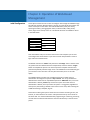
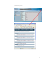
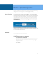
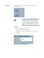
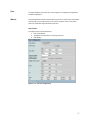
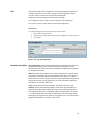
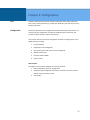
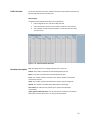
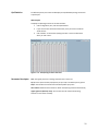
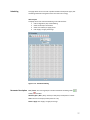
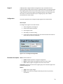
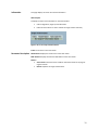
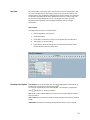
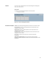
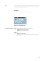
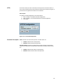
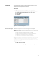
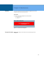
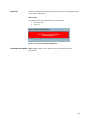
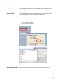
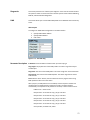
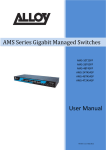
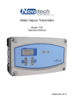
MaxiiNetTM VI3026 Quick Set-Up Guide 20 GE PoE-Plus + 4 GE PoE-Plus Combo SFP + 2 GE SFP L2 26 Port Managed Switch Release 2.35 / Firmware Version 1.0 2013 Vigitron, Inc. All rights reserved. All brand and product names are trademarks or registered trademarks of their respective companies. About This Manual Copyright Copyright © Vigitron, Inc. 2013. All rights reserved. MaxiiNet is a trademark of Vigitron Corporation. The products and programs described in this User’s Manual are licensed products of Vigitron, Inc.. This User’s Manual contains proprietary information protected by copyright, and this User’s Manual and all accompanying hardware, software and documentation are copyrighted. No parts of this User’s Manual may be copied, photocopied, reproduced, translated, or reduced to any electronic medium or machine-readable by any means - electronic or mechanical. This includes photocopying, recording, or information storage and retrieval systems, for any purpose other than the purchaser’s personal use, and without the prior express written permission of Vigitron. Purpose This manual provides specific information on how to program and operate the management functions of the Vi3026. Audience The manual is intended for use by network administrators who are responsible for operating and maintaining network equipment; consequently, it assumes a basic working knowledge of general switch functions, the Internet Protocol (IP), and Simple Network Management Protocol (SNMP). Conventions The following conventions are used throughout this manual to show information. NOTE: Emphasizes important information or calls your attention to related features or instructions. WARNING: Alerts you to a potential hazard that could cause personal injury. CAUTION: Alerts you to a potential hazard that could cause loss of data, or damage the system or equipment. Warranty See the Customer Support/Warranty booklet included with the product. A copy of the specific warranty terms applicable to your Vigitron products and replacement parts can be obtained from your Vigitron’s Sales and Service Office authorized dealer. 2 Disclaimer Vigitron, Inc. does not warrant that the hardware will work properly in all environments and applications, and marks no warranty and representation, either implied or expressed, with respect to the quality, performance, merchantability, or fitness for a particular purpose. Vigitron disclaims liability for any inaccuracies or omissions that may have occurred. Information in this User’s Manual is subject to change without notice and does not represent a commitment on the part of Vigitron. Vigitron assumes no responsibility for any inaccuracies that may be contained in this User’s Manual. Vigitron makes no commitment to update or keep current the information in this User’s Manual, and reserves the rights to make improvements to this User’s Manual and/or to the products described in this User’s Manual, at any time without notice. FCC Warning This equipment has been tested and found to comply with the limits for a Class A digital device, pursuant to Part 15 of the CE/FCC remove rules. These limits are designed to provide reasonable protection against harmful interference when the equipment is operated in a commercial environment. This equipment generates, uses, and can radiate radio frequency energy and, if not installed and used in accordance with the Instruction manual, may cause harmful interference to radio communications. FCC Caution To assure continued compliance: (for example, use only shielded interface cables when connected to a computer or peripheral devices). Any changes or modifications not expressly approved by the party responsible for compliance could void the user’s authority to operate the equipment. This device complies with Part 15 of the FCC Rules. Operation is subject to the following two conditions: (1) This device may not cause harmful interference, and (2) this device must accept any interference received, including interference that may cause undesired operation. CE Mark Warning This is a Class A device, in a domestic environment, this product may cause radio interference, in which case the user may be required to take adequate measures. UL Mark Revision History Ul 60950-1 Information Technology Equipment - Safety - Part 1: General Requirements - Edition 2 - Revision Date 2014/05/13 Release Date Revision V2.35 12/01/2103 A1 3 Table of Contents ABOUT THIS MANUAL ............................................................................................................................................ 2 REVISION HISTORY .........................................................................................................................................................3 INTRODUCTION ..................................................................................................................................................... 6 OVERVIEW....................................................................................................................................................................6 CHAPTER 1: OPERATION OF WEB-BASED MANAGEMENT....................................................................................... 7 INITIAL CONFIGURATION ..................................................................................................................................................7 CONNECTING NETWORK DEVICES....................................................................................................................................10 TWISTED-PAIR DEVICES.................................................................................................................................................10 CABLING GUIDELINES....................................................................................................................................................10 CHAPTER 2: SYSTEM CONFIGURATION ................................................................................................................. 12 SYSTEM INFORMATION ..................................................................................................................................................12 CONFIGURATION ..........................................................................................................................................................15 TIME .........................................................................................................................................................................17 MANUAL ....................................................................................................................................................................17 IP .............................................................................................................................................................................19 IPV4 .........................................................................................................................................................................19 IPV6 .........................................................................................................................................................................21 CHAPTER 3: CONFIGURATION .............................................................................................................................. 22 PORT .........................................................................................................................................................................22 CONFIGURATION ..........................................................................................................................................................22 PORT DESCRIPTION ......................................................................................................................................................25 TRAFFIC OVERVIEW ......................................................................................................................................................26 DETAILED STATISTICS .....................................................................................................................................................27 QOS STATISTICS ...........................................................................................................................................................29 SFP INFORMATION .......................................................................................................................................................30 POE ..........................................................................................................................................................................31 STATUS ......................................................................................................................................................................33 POWER DELAY .............................................................................................................................................................34 AUTO CHECKING ..........................................................................................................................................................35 SCHEDULING ...............................................................................................................................................................37 SINGLE IP ...................................................................................................................................................................38 INFORMATION .............................................................................................................................................................39 EASY PORT .................................................................................................................................................................40 CHAPTER 4: SECURITY .......................................................................................................................................... 42 ACCESS MANAGEMENT .................................................................................................................................................42 STATISTICS ..................................................................................................................................................................44 SSH ..........................................................................................................................................................................45 HTTPS ......................................................................................................................................................................46 AUTH METHOD ...........................................................................................................................................................47 CHAPTER 5: MAINTENANCE ................................................................................................................................. 48 SAVE START ................................................................................................................................................................48 SAVE USER .................................................................................................................................................................49 RESTORE USER ............................................................................................................................................................50 EXPORT/IMPORT .........................................................................................................................................................51 4 EXPORT CONFIG ..........................................................................................................................................................51 IMPORT CONFIG ..........................................................................................................................................................52 DIAGNOSTICS ..............................................................................................................................................................53 PING ........................................................................................................................................................................53 PING6 ......................................................................................................................................................................54 CONTACT INFORMATION ..................................................................................................................................... 55 5 Introduction Overview This user’s manual guides the user on installing and connecting the network system. It also gives guidane on configuring and monitoring the Vi3026 through the web by (RJ-45) serial interface and Ethernet ports. There are detailed explanations of hardware and software functions, along with examples of web-based interface operations. Known as the next generation web managed switches from Vigitron, the Vi3026 is a portfolio of an affordable managed switch that provides a reliable infrastructure for your business network. The Vi3026 delivers intelligent features you need to improve the availability of your critical business applications, protect your sensitive information, and optimize your network bandwidth to deliver information and applications more effectively. It provides the ideal combination of affordability and capabilities for entry level networking, including small business or enterprise application to help you create a more efficient and better-connected workforce. The Vi3026 web managed switch provides 26 ports in a single device. The specifications are highlighted below: L2+ features provide better manageability, security, QoS, and performance. High port count design with all Gigabit Ethernet ports. Support guest VLAN, voice VLAN, port based, tag-based and protocolbased VLANs. Support 802.3az energy efficient Ethernet standard. Support 8K MAC table. Support IPv6/ IPv4 dual stack. Support s-Flow. Support easy-configuration-port for easy implement the IP phone, IP camera or wireless environment. Jumbo Frame transmission for up to 9600 bytes at all network speeds. 576W power supply with 370W PoE budget. Overview of this User’s Manual Chapter 1 “Operation of Web-based Management” Chapter 2 “System Configuration” Chapter 3 “Configuration” Chapter 4 “Security” Chapter 5 “Maintenance” 6 Chapter 1: Operation of Web-Based Management Initial Configuration This chapter instructs the user on how to configure and manage the Vi3026 through the web user interface. With this facility, the user can easily access and monitor the status of each port on the switch. This includes MIB status, each port activity, spanning tree status, port aggregation status, multicast traffic, VLAN, priority status, illegal access record, and so on. The default values for the Vi3026 are listed in the table below: IP Address 192.168.1.1 Subnet Mask 255.255.255.0 Default Gateway 192.168.1.254 Username admin Password Once the Vi3010 is setup on the same network as a host computer you can view and configure the switch features. Input the username and password in order to login and access authentication. The default username is “admin” and password is left empty. If this is the first time use, please enter the default username and password, and then click the <Login> button to complete the process. You have to input the complete username and password respectively within the login menu. The Vi3026 will not automatically give you a shortcut to the username. This may be inconvenient, but it is the safer option. The Vi3026 supports a simple user management function to allow only one administrator to configure the system at any one time. The use of simultaneous administrators could result in unpredictable operation. Additional users, even with administrator’s identity, should only monitor the system. Those who have no administrator’s identity can only monitor the system. It is suggested, regardless of security level, that viewing is limited to one client at a time. Also, after accessing the Vi3026 and viewing is complete, log out. Connections involving the input of routers and use of clients accessing servers, the internet, or other networks can result in a brief disconnection of client's access to the switch GUI. It is recommended that after programming or monitoring, clients log out and that users without administrator access be allowed only a minimal access period. 7 NOTE: In order to manage the switch via the web, you must login with the default username and password. For first time use, the username is “Admin” and the password is left blank. Press “login” to complete the process. You can use both IPv4/IPV6 to manage the switch. To optimize the display effect, we recommend Microsoft IE 6.0 above, Netscape V7.1 above, or FireFox V1.00 above, and have a resolution of 1024x768. The switch supported neutral web browser interface. If the UI is not working with the FireFox browser, it might result from PC security system setting. NOTE: The Vi3026 function enables DHCP. If you do not have the DHCP server to provide IP addresses to the switch, the switch’s default IP is 192.168.1.1. The server 192.168.20.15 at Vi3026 requires a username and password. Figure 1: The Login Page NOTE: If you need to configure the function or parameter, then refer to the detailed user guide. You could also learn how to set up the parameters by clicking on “Help” under the web GUI. 8 Vi3026 Web Help Function: 9 Connecting Network Devices The switch is designed to be connected to 10, 100, or 1000Mbps network cards in PCs and servers, and to other switches and hubs. It may also be connected to remote devices using optional SFP transceivers. Twisted-Pair Devices Each device requires an unshielded twisted-pair (UTP) cable with RJ-45 connectors at both ends. Use Category 5, 5e, or 6 cable for 1000BASE-T connections, and Category 5 or better for 100BASE-TX connections. Cabling Guidelines The RJ-45 ports on the switch support automatic MDI/MDI-X pin-out configuration. You could use the standard straight-through twisted-pair cables to connect to any other network device (PCs, servers, switches, routers, or hubs). See Appendix B for further information on cabling. CAUTION: Do not plug a phone jack connector into an RJ-45 port. This will damage the switch. Use only twisted-pair cables with RJ-45 connectors that conform to FCC standards. CONNECTING TO PCS, SERVERS, HUBS AND SWITCHES Step 1. Attach one end of a twisted-pair cable segment to the device’s RJ-45 connector. Figure 16: Making Twisted-Pair Connections Step 2. If the device is a network card and the switch is in the wiring closet, attach the other end of the cable segment to a modular wall outlet that is connected to the wiring closet (see the section “Network Wiring Connections”). Otherwise, attach the other end to an available port on the switch. Make sure each twisted pair cable does not exceed 100 meters (328ft) in length. If distances longer than 100 meters (328ft) are required or the requirement is to transmit PoE and IP video (data) over coax, please contact Vigitron for extended distance UTP and coax solutions. 10 NOTE: Avoid using flow control on a port connected to a hub, unless it is actually required to solve a problem. Otherwise, back pressure jamming signals may degrade overall performance for the segment attached to the hub. Step 3. As each connection is made, the switch LED’s corresponding to each port will light according to the following chart. LED Conditions Status TP (Link/ACT) Green Green when the TP link is good. Blinks when any traffic is present. PoE Green Green when the port is delivering PoE power. SFP (Link/ACT) Green/Amber Green when the SFP link is 1000Mp/s. Amber when the SFP link is 100Mb/s. Blinks when any traffic is present. NETWORK WIRING CONNECTIONS Today, the punch-down block is an integral part of many of the newer equipment racks. It is actually part of the patch panel. Instructions for making connections in the wiring closet with this type of equipment follows: Step1. Attach one end of a patch cable to an available port on the switch, and the other end to the patch panel. Step2. If not already in place, attach one end of a cable segment to the back of the patch panel where the punch-down block is located, and the other end to a modular wall outlet. Step3. Label the cables to simplify future troubleshooting. See “Cable Labeling and Connection Records” on page 29. Equipment Rack (side view) Switch Patch-Down Block Patch Panel Wall Figure 17: Network Wiring Connections 11 Chapter 2: System Configuration Chapter 2 describes basic configuration tasks including system information and any management of the switch (e.g. time, account, IP, syslog, and SNMP). System Information The system information will appear after you logged in. This is the default page. It show the basic information of the system, including model name, system description, contact, device’s name, system up time, BIOS version, firmware version, hardwaremechanical version, serial number, host IP address, host mac address, device port, RAM size, and flash size. With this information, you will know the software version used, MAC address, serial number, how many ports good and so on. This is helpful while malfunctioning. Auto Logout is defaulted for 10 minutes after which the operation will have to reenter the username and password. This feature can be turned off or the duration can be changed using the drop down menu. Information The switch system information is provided here. Web interface To configure System Information in the web interface: 1. Click SYSTEM, System, and Information. 2. Specify the contact information for the system administrator and the name and location of the switch. Also indicate the local time zone by configuring the appropriate offset. 3. Click “Refresh”. 12 Figure 2-1.1: System Information (e.g. Vi3026/Other models are the same) Parameter Description Model name: The model name of this device. System description: This describes what the device is. In this example, it is “20-Port 10/100/1000Base-T + 4 TP/(100/1G) SFP Combo + 2 (100/1G) SFP PoE+ L2 Plus Managed Switch”. Location: The location in which the user defined where this switch is put. Contact: For easy managing and maintaining device, write down the contact person and their phone number here for getting help soon. You can configure this parameter through the device’s user interface or SNMP. Device name: The name of the switch in which the user defined. System Date: Shows the system time of the switch. Its format: day of week, month, day, hours: minutes: seconds, year. System up time: The time accumulated since this switch is powered up. Its format is day, hour, minute, second. BIOS version: The version of the BIOS in this switch. Firmware version: The firmware version in this switch. Hardware-Mechanical version: The version of Hardware and Mechanical. The figure before the hyphen is the version of electronic hardware. The one after the hyphen is the version of mechanical. Serial number: The serial number is assigned by the Manufacture. Host IP address: The IP address of the switch. Subnet Mask: Displays the IP subnet mask assigned to the device. Gateway IP Address: Displays the default gateway IP address assigned to the device. Host MAC address: It is the Ethernet MAC address of the management agent in this switch. Console Baudrate: Displays the baudrate of RJ45(COM) port. RAM size: The size of the RAM in this switch. 13 Flash size: The size of the flash memory in this switch. CPU Load: Displays the load measured as averaged over the last 100ms, 1sec and 10 seconds intervals. Bridge FDB size: Displays the bridge FDB size information. Transmit Queue: Displays the device’s transmit hardware priority queue information. Maximum Frame size: To display the device’s maximum frame size information. 14 Configuration You can identify the system by configuring the contact information, name, and location of the switch. WARNING: In order to save programming changes, go to the Maintenance function and select either “Save Start”, which will allow for all changes to save upon start up or “Save User”, which will apply changes to only the logged in user. All changes must be saved or the system will revert to its default setting for any power down and restart. Web interface To configure System Information in the web interface: 1. Click System, System Information, Configuration. 2. Write System Contact, System Name, System Location information in this page. 3. Click “Apply”. Figure 2-1.2: System Information Configuration 15 Parameter Description System Contact: The textual identification of the contact person for this managed node, together with information on how to contact this person. The allowed string length is 0 to 255, and the allowed content is the ASCII characters from 32 to 126. System Name: An administratively assigned name for this managed node. By convention, this is the node's fully-qualified domain name. A domain name is a text string drawn from the alphabet (A-Za-z), digits (0-9), minus sign (-). No space characters are permitted as part of a name. The first character must be an alpha character. And the first or last character must not be a minus sign. The allowed string length is 0 to 255. System Location: The physical location of this node (I.e. telephone closet, 3rd floor). The allowed string length is 0 to 255, and the allowed content is the ASCII characters from 32 to 126. 16 Time Manual This page configures the switch time. Time configure is including time configuration and NTP configuration. The switch provides manual and automatic ways to set the system time via NTP. With manual setting, you simply input the year, month, day, hour, minute, and second within the valid value range indicated in each item. Web Interface To configure Time in the web interface: 1. Click Time, Manual. 2. Specify the time parameter in manual parameters. 3. Click “Apply”. Figure 2-2.1: The Time Configuration 17 Parameter Description Clock Source: Select the clock source for the Vi3026 by clicking on “Use local Settings” or “Use NTP Server”. Time Format: The drop bar is for choose appropriate time format. Three selections are provided. YYYY-MM-DD HH:MM:SS MM-DD-YYYY HH:MM:SS DD-MM-YYYY HH:MM:SS 24 hours: The time is always represented in the 24-hour system 12 hours: The time is always represented in the 12-hour system Local Time: Shows the current time of the system. Time Zone Offset: Provides the time zone offset relative to UTC/GMT. The offset is given in minutes east of GMT. The valid range is from -720 to 720 minutes. Daylight Saving: Daylight saving is adopted in some countries. If set, it will adjust the time lag or in advance in unit of hours, according to the starting date and the ending date. For example, if you set the daylight saving to be 1 hour. When the time passes over the starting time, the system time will be increased one hour after one minute at the time since it passed over. And when the time passes over the ending time, the system time will be decreased one hour after one minute at the time since it passed over. The switch supports valid configurable day light saving time is –5 ~ +5 step one hour. The zero for this parameter means it need not have to adjust current time, equivalent to in-act daylight saving. You don’t have to set the starting/ending date as well. If you set daylight saving to be non-zero, you have to set the starting/ending date as well; otherwise, the daylight saving function will not be activated. Time Set Offset: Provide the daylight saving time set offset. The offset is given in minutes east of GMT. The valid range is from 1 to 1440 minutes. Default is 60 minutes. Daylight Savings Type: Provide the daylight savings type selection. You can select “By Dates” or “Recurring” two types for daylight saving type. From: To configure when daylight saving start date and time, the format is “YYYYMM-DD HH:MM”. To: To configure when daylight saving end date and time, the format is “YYYY-MMDD HH:MM”. NOTE: The under “from” and “to” was displayed what you set on the “From” and “To” field information. 18 IP IP is an acronym for Internet Protocol. It is a protocol used for communicating data across an internet network. IP is a "best effort" system, which means that no packet of information sent over is assured to reach its destination in the same condition it was sent. Each device connected to a Local Area Network (LAN) or Wide Area Network (WAN) is given an Internet Protocol address, and this IP address is used to identify the device uniquely among all other devices connected to the extended network. The current version of the Internet protocol is IPv4, which has 32-bits Internet Protocol addresses allowing for in excess of four billion unique addresses. This number is reduced drastically by the practice of webmasters taking addresses in large blocks, the bulk of which remain unused. There is a rather substantial movement to adopt a new version of the Internet Protocol, IPv6, which would have 128-bits Internet Protocol addresses. This number can be represented roughly by a three with thirty-nine zeroes after it. However, IPv4 is still the protocol of choice for most of the Internet. IPv4 The IPv4 address for the switch could be obtained via DHCP Server for VLAN 1. To manually configure an address, you need to change the switch's default settings to values that are compatible with your network. You may also need to establish a default gateway between the switch and management stations that exist on another network segment. Configure the switch-managed IP information on this page. The “Configured” column is used to view or change the IP configuration. The “Current” column is used to show the active IP configuration. Web Interface To configure an IP address in the web interface: 1. 2. 3. Click System, IP Configuration. Specify the IPv4 settings, and enable DNS proxy service if required. Click “Apply”. 19 Figure 2- 3.1: The IP configuration Parameter Description DHCP Client: Enable the DHCP client by checking this box. If the DHCP fails and the configured IP address is zero, the DHCP will retry. If the DHCP fails and the configured IP address is non-zero, the DHCP will stop and the configured IP settings will be used. The DHCP client will announce the configured “System Name” as hostname to provide DNS lookup. IP Address: Provides the IP address of this switch in dotted decimal notation. IP Mask: Provides the IP mask of this switch dotted decimal notation. IP Gateway: Provides the IP address of the router in dotted decimal notation. VLAN ID: Provides the managed VLAN ID. The allowed range is 1 to 4095. DNS Server: Provides the IP address of the DNS Server in dotted decimal notation. DNS Proxy: When DNS proxy is enabled, the DUT will relay DNS requests to the current configured DNS server on DUT, and reply as a DNS resolver to the client device on the network. 20 IPv6 This section describes how to configure the switch-managed IPv6 information. The “Configure”d column is used to view or change the IPv6 configuration. And the “Current” column is used to show the active IPv6 configuration. Configure the switch-managed IPv6 information on this page. The “Configured” column is used to view or change the IPv6 configuration. The “Current” column is used to show the active IPv6 configuration. Web Interface To configure Management IPv6 of the switch in the web interface: 1. Click System, IPv6 configuration. 2. Specify the IPv6 settings, and enable the“Auto Configuration” service if required. 3. Click “Apply”. Figure 2- 3.2: The IPv6 Configuration Parameter Description Auto Configuration: Enable IPv6 auto-configuration by checking this box. If fails, the configured IPv6 address is zero. The router may delay responding to a router solicitation for a few seconds, the total time needed to complete auto-configuration can be significantly longer. Address: Provides the IPv6 address of this switch. IPv6 address is in 128-bit records represented as eight fields of up to four hexadecimal digits with a colon separating each field (:). For example, 'fe80::215:c5ff:fe03:4dc7'. The symbol '::' is a special syntax that can be used as a shorthand way of representing multiple 16-bit groups of contiguous zeros; but it can only appear once. It can also represent a legally valid IPv4 address. For example, '::192.1.2.34'. Prefix: Provides the IPv6 Prefix of this switch. The allowed range is 1 to 128. Gateway: Provides the IPv6 gateway address of this switch. The IPv6 address is in 128-bit records represented as eight fields of up to four hexadecimal digits with a colon separating each field (:). For example, 'fe80::215:c5ff:fe03:4dc7'. The symbol '::' is a special syntax that can be used as a shorthand way of representing multiple 16-bit groups of contiguous zeros; but it can only appear once. It can also represent a legally valid IPv4 address. For example, '::192.1.2.34'. 21 Chapter 3: Configuration Port Chapter 3 describes all of the basic network configuration tasks which includes the ports, layer 2 network protocol (e.g. VLANs, QoS, IGMP, ACLs, PoE and more) and any setting of the switch. Configuration The section describes how to configure the port detail parameters of the switch. You could use the port configuration to enable or disable the port of the switch, and monitor the ports content or status in the function. Learn how to view the current port configuration and how to configure ports to nondefault settings, including: 1. Linkup/Linkdown 2. Speed (Current and configured) 3. Flow Control (Current Rx, Current Tx and Configured) 4. Maximum Frame Size 5. Excessive Collision Mode 6. Power Control Web Interface To configure a Current Port Configuration in the web interface: 1. Click Configuration, Port, then Configuration 2. Specify the speed configured, flow control, maximum frame size, excessive collision mode, and power control. 3. Click “Apply”. 22 Figure 3-1.1: The Port Configuration Parameter Description Port: This is the logical port number for this row. Link: The current link state is displayed graphically. Green indicates the link is up and red indicates that the link is down. Current Link Speed: Provides the current link speed of the port. Configured Link Speed: Selects any available link speed for the given switch port. Only speeds supported by the specific port are shown. Possible speeds are: a. Disabled - Disables the switch port operation. b. Auto - Cu port auto negotiating speed with the link partner and selects the highest speed that is compatible with the link partner. c. 10Mbps HDX - Forces the cu port in 10Mbps half-duplex mode. d. 10Mbps FDX - Forces the cu port in 10Mbps full duplex mode. e. 100Mbps HDX - Forces the cu port in 100Mbps half-duplex mode. f. 100Mbps FDX - Forces the cu port in 100Mbps full duplex mode. g. 1Gbps FDX - Forces the cu port in 1Gbps full duplex mode. h. Important! Please note SFP_Auto_AMS - Automatically determines the speed of the SFP. There is no standardized way to do SFP auto detect, so here it is done by reading the SFP rom. Due to the missing standardized way of doing SFP auto detect some SFPs might not be detectable. The port is set in AMS mode with SFP preferred. Cu port is set in Auto mode. i. 100-FX - SFP port in 100-FX speed. Cu port disabled. j. 100-FX_AMS - Port in AMS mode with SFP preferred. SFP port in 100-FX speed. Cu port in Auto mode. k. 1000-X - SFP port in 1000-X speed. Cu port disabled. 23 l. 100-X_AMS - Port in AMS mode with SFP preferred. SFP port in 1000-X speed. m. Cu port in Auto mode. Flow Control: When “Auto Speed” is selected on a port, this section indicates the flow control capability that is advertised to the link partner. When a fixed-speed setting is selected, that is what is used. The “Current Rx” column indicates whether pause frames on the port are obeyed, and the “Current Tx” column indicates whether pause frames on the port are transmitted. The Rx and Tx settings are determined by the result of the last “Auto-Negotiation”. Check the “Configured” column to use flow control. This setting is related to the setting for configured link speed. Maximum Frame Size: Enter the maximum frame size allowed for the switch port, including FCS. Excessive Collision Mode : a. Configure port transmit collision behavior. b. Discard: Discards the frame after 16 collisions (default). c. Restart: Restarts the backoff algorithm after 16 collisions. Power Control: The “Usage” column shows the current percentage of the power consumption per port. The “Configure”d column allows for changing the power savings mode parameters per port. a. Disabled: All power savings mechanisms are disabled. b. ActiPHY: Link down power savings is enabled. c. PerfectReach: Link up power savings is enabled. d. Enabled: Both link up and link down power savings are enabled. Buttons a. Apply – Click to save changes. b. Reset- Click to undo any changes made locally and revert to previously saved values. Upper right icon (Refresh): You can click them for refresh the port link status manually. 24 Port Description The section describes to configure the port’s alias or any descriptions for the port identity. It provides user to write down an alphanumeric string describing the full name and version identification for the system’s hardware type, software version, and networking application. Web Interface To configure a Port Description in the web interface: 1. Click Configuration, Port, and then Port Description. 2. Specify the descriptive port alias in an alphanumeric string, describing the full name and version identification for the system’s hardware type, software version, and networking application. 3. Click “Apply”. Figure 3-1.2: The Port Configuration Parameter Description Port: This is the logical port number for this row. Description: Enter up to 47 characters to be descriptive name for identifies this port. Buttons Apply – Click to save changes. Reset- Click to undo any changes made locally and revert to previously saved values. After port naming is apply the name can be seen by moving the mouse over the corresponding port in the switch icon at the top of the screen. 25 Traffic Overview The section describes to the port statistics information and provides overview of the general traffic statistics for all switch ports. Web Interface To display the Port Statistics Overview in the web interface: 1. Click Configuration, Port, and then Traffic Overview. 2. If you want to auto-refresh, then you need to evoke the “Auto-refresh”. 3. Click “Refresh“ to refresh the port statistics or clear all information when you click “Clear”. Figure 3-1.3: The Port Statistics Overview Parameter Description Port: The logical port for the settings contained in the same row. Packets: The number of received and transmitted packets per port. Bytes: The number of received and transmitted bytes per port. Errors: The number of frames received in error and the number of incomplete transmissions per port. Drops: The number of frames discarded due to ingress or egress congestion. Filtered: The number of received frames filtered by the forwarding. Auto-refresh: To evoke the auto-refresh icon to refresh the information automatically. Upper right icon (Refresh, Clear): You can click them to refresh the port statistics information manually. Click “Clear” to clean up all port statistics. 26 Detailed Statistics The section provides detailed traffic statistics for a specific switch port. Use the port select box to select which switch port details to display. The displayed counters are the totals for receive and transmit, the size counters for receive and transmit, and the error counters for receive and transmit. Web Interface To display the port detailed statistics Overview in the web interface: 1. Click Configuration, Port, and then Detailed Port Statistics 2. Scroll the port index to select which port you want to show the detailed port statistics overview. 3. If you want to auto-refresh the information, then you need to evoke “Autorefresh”. 4. Click “Refresh“ to refresh the port detailed statistics or clear all information when you click “Clear”. Figure 3-1.4: The Port Detail Statistics Overview Parameter Description Auto-refresh: To evoke the auto-refresh to refresh the port statistics information automatically. Upper left scroll bar: To scroll which port to display the port statistics with “Port-0”, “Port-1”... Receive Total and Transmit Total Rx and Tx Packets: The number of received and transmitted (good and bad) packets. Rx and Tx Octets: The number of received and transmitted (good and bad) bytes. Includes FCS, but excludes framing bits. Rx and Tx Unicast: The number of received and transmitted (good and bad) unicast packets. Rx and Tx Multicast: The number of received and transmitted (good and bad) multicast packets. Rx and Tx Broadcast: The number of received and transmitted (good and bad) broadcast packets. 27 Rx and Tx Pause: A count of the MAC Control frames received or transmitted on this port that have an opcode indicating a PAUSE operation. Receive and Transmit Size Counters The number of received and transmitted (good and bad) packets split into categories based on their respective frame sizes. Receive and Transmit Queue Counters The number of received and transmitted packets per input and output queue. Receive Error Counters Rx Drops: The number of frames dropped due to lack of received buffers or egress congestion. Rx CRC/Alignment: The number of frames received with CRC or alignment errors. Rx Undersize: The number of short 1 frames received with valid CRC. Rx Oversize: The number of long 2 frames received with valid CRC. Rx Fragments: The number of short 1 frames received with invalid CRC. Rx Jabber: The number of long 2 frames received with invalid CRC. Rx Filtered: The number of received frames filtered by the forwarding process. Short frames are frames that are smaller than 64 bytes. Long frames are frames that are longer than the configured maximum frame length for this port. Transmit Error Counters Tx Drops: The number of frames dropped due to output buffer congestion. Tx Late/Exc. Coll.: The number of frames dropped due to excessive or late collisions. Auto-refresh: To evoke the auto-refresh to refresh the queuing counters automatically. Upper right icon (Refresh, clear): You can click them for refresh the port detail statistics or clear them manually. 28 QoS Statistics For different queues, the switch could display the QoS detailed queuing counters for a specific port. Web Interface To display the Queuing Counters in the web interface: 1. Click Configuration, Port, and then QoS Statistics. 2. If you want to auto-refresh the information, then you need to evoke the “Auto-refresh”. 3. Click “Refresh” to refresh the Queuing Counters or clear all information when you click “Clear”. Figure 3-1.5: The Queuing Counters Overview Parameter Descripton Port: The logical port for the settings contained in the same row. Qn: Qn is the Queue number, QoS queues per port. Q0 is the lowest priority queue. Rx/Tx: The number of received and transmitted packets per queue. Auto-refresh: Evoke the auto-refresh to refresh the Queuing Counters automatically. Upper right icon (Refresh, clear): You can click them for refresh the Queuing Counters or clear them manually. 29 SFP Information The switch could display the SFP module detail information which you connect it to the switch. The information includes: connector type, fiber type, wavelength, baud rate, vendor OUI, and etc. The information read can differ depending on the SFP used. Some SFP many not provide all information categories. Web Interface To display the SFP information in the web interface: 1. Click Configuration, Port, and then SFP Information. 2. To display the SFP Information, cick “Apply”. Figure 3-1.6: The SFP Information Overview Parameter Description Connector Type: Displays the connector type (e.g. UTP, SC, ST, LC and so on). Fiber Type: Displays the fiber mode (e.g. Multi-Mode, Single-Mode). Tx Central Wavelength: Displays the fiber optical transmitting central wavelength (e.g. 850nm, 1310nm, 1550nm and so on). Baud Rate: Displays the maximum baud rate of the fiber module supported (e.g. 10M, 100M, 1G and so on). Vendor OUI: Displays the Manufacturer's OUI code which is assigned by IEEE. Vendor Name: Displays the company name of the module manufacturer. Vendor P/N: Displays the product name of the naming by module manufacturer. Vendor Revision: Displays the module revision. Vendor Serial Number: Shows the serial number assigned by the manufacturer. Date Code: Shows the date this SFP module was made. Temperature: Shows the current temperature of SFP module. Vcc: Shows the working DC voltage of SFP module. Mon1(Bias) mA: Shows the Bias current of SFP module. Mon2(TX PWR): Shows the transmit power of SFP module. Mon3(RX PWR): Shows the receiver power of SFP module. 30 PoE PoE is an acronym for Power over Ethernet. Power over Ethernet is used to transmit electrical power to remote devices over standard Ethernet cable. It could be used for powering IP video cameras, PoE LEDs, IP telephones, wireless LAN access point,s and other equipment, where it would be difficult or expensive to connect the equipment to main power supply. Configuration This page allows the user to inspect and configure the current PoE port settings and show all PoE Supply Watts. Web Interface To configure Power over Ethernet in the web interface: 1. Click “Configuration”. 2. Specify the Reserved Power determined and Power Management ode. Specify the PoE or As 802.3af (15.4 watts) or 802.3at (30 watts) and priority. 3. Click “Apply”. Figure 3-9.1: The PoE Configuration 31 Parameter Description Power Supply Configuration Primary Power Supply [W]: The switch can have PoE power supplies. It is used as power source to determine the amount of power the PD may use. It must be defined what amount of power the power sources can deliver. PoE Power: The PoE power supply settings will be shown. Power Allocated for PoE: The total of Maximum Power. As power per port is allocated, this figure will increase. A pop up will be displayed when the total value of the available PoE power is exceeded. Power Available for PoE: Power Available for PoE. Retry Rime: The period (in seconds) for trying to turn on an overloaded PoE port. If a port becomes overloaded for any reason, the power will shut down and an attempt to repower will be made depending on the time set. Ethernet Port Configuration Port: This is the logical port number for this row. PoE Mode: The PoE mode represents the PoE operating mode for the port. Disabled: PoE disabled for the port. Enabled: Enables PoE IEEE 802.3af/at Priority: “Priority” represents the ports priority. There are three levels of power priority named Low, High, and Critical. The priority is used in the case where the remote device requires more power than the power supply can deliver. In this case, the port with the lowest priority will be turn off starting from the port with the highest port number. Maximum Power: The maximum power value contains a numerical value that indicates the maximum power in watts that can be delivered to a remote device. Detection: “Detection” represents the PoE capacitor detection for the port. Legacy: Legacy capacitive detection only. 4-point: IEEE 802.3af 4-point detection only. Both: IEEE 802.3af 4-point detection followed by legacy detection. Reset: Resets the specific PoE port. NOTE: If you want to set the port support IEEE802.3at, then you can set the maximum allowed value to 30W. Buttons: Apply – Click to save changes. Reset – Click to undo any changes made locally and revert to previously saved values. 32 Status This page allows the user to inspect the current status for all PoE ports. The section shows all port Power over Ethernet status. Web Interface To display Power over Ethernet Status in the web interface: 1. Click “Status”. 2. Display Power over Ethernet Status Information. 3. Click “Refresh”. Figure 3-9.2: The Power over Ethernet Status Parameter Description Local Port: This is the logical port number for this row. PD Class: Displays the PD Power class that identify with a specified current. The classification current describes the amount of power the PD will require during normal operation. Power Requested: “Power Requested” shows the requested amount of power the PD wants to be reserved. Power Allocated: “Power Allocated” shows the amount of power the switch has allocated for the PD. Power Used: “Power Used” shows how much power the PD currently is using. Current Used: “Power Used” shows how much current the PD currently is using. Priority: “Priority” shows the port's priority configured by the user. Port Status: “Port Status” shows the port's status. If no PD is detecte,d the camera will not power up. There will be no PD Class or Power Requested. Auto-refresh: Evoke the auto-refresh icon to refresh the information automatically. Upper right icon (Refresh): You can click them for refresh the PoE Port information manually. 33 Power Delay This page allows the user to set the delay time of power provided after the device rebooted. Web Interface To display Power over Ethernet Status in the web interface: 1. Click Configuration, PoE, and Power delay. 2. Enable the port to the power device. 3. Specify the power providing delay time when reboot. 4. Click “Apply” to apply the change. Figure 3-9.3: The POE Power Delay Parameter Description Port: This is the logical port number for this row. Delay Mode: Turn on/off the power delay function. Delay Time (0~300sec): When rebooting, the PoE port will start to provide power to the PD when it out of delay time. Button: Apply - Click “Apply” to apply the change. 34 Auto Checking This page allows the user to specify the auto detection parameters to check the linking status between PoE ports and PDs. When it detected the fail connect, it will reboot the remote PD automatically. Web Interface To Display Power over Ethernet Auto Checking in the web interface: 1. Click Configuration, PoE, and Auto checking. 2. Enable the Ping Check function. 3. Specify the PD’s IP address, checking interval, retry time, failure action, and reboot time. 4. Click “Apply” to apply the change. Figure 3-9.4: The POE Auto Checking 35 Parameter Description Ping Check: Enables the Ping Check function to detect the connection between PoE port and power device. “Disable” will turn off the detection. Port: This is the logical port number for this row. Ping IP Address: The PD’s IP dddress the system should ping. Interval Time (sec): Device will send checking message to PD each interval time. Retry Time: When PoE port can’t ping the PD, it will retry to send detection again. When the third time, it will trigger failure action. Failure Log: Failure loggings counter. Failure Action: The action when the third fail detection. Nothing- Keeps pinging the remote PD but does nothing further. Reboot Remote PD- Cuts off the power of the PoE port, then make the PD reboot. Reboot Time: After the PD reboots, the PoE port restores power after the specified time. Button: Apply- Click “Apply” to apply the change. 36 Scheduling This page allows the user to make a perfect schedule of PoE power supply. PoE scheduling makes PoE management easier and saves more energy. Web Interface To display Power over Ethernet Scheduling in the web interface: 1. Click Configuration, PoE, and Scheduling. 2. Select the local port and enable. 3. Select time and day to supply power. 4. Click “Apply” to apply the change. Figure 3-9.5: The POE Scheduling Parameter Description Port / Status: This is the logical port number and thePoE scheduling mode. enable; is is disable. Week Day (Sun., Mon., etc…): The days of PoE port provide power of a week. Hour: The time of PoE port provide power of a day. Button: Apply- Click “Apply” to apply the change. 37 Single IP Vi3026 provides a single IP address management of up to 32 switches and not limited to specific models, distance barriers, specialized cables, and stacking method. Each single IP group consists of one master switch, and up to 32 slave switches. The master switch is used to be an agent to manage all switches in the same group. The slave switch is a switch which wants to join a single IP group, and it could be accessed from the master switch. Configuration The section describes how to setting the single IP group in this web interface. Web Interface To configure the Single IP in the web interface: 1. Click Configuration, then Single IP. 2. Choose what mode the switch is. 3. Give the group name. 4. Click “Apply” to save the setting. 5. If you want to cancel the setting, then you need to click the reset button to revert back to previously saved values. Figure 3-18.1: The Single IP Configuration Parameter Description Mode: Possible modes are – Disable: Disables operation of single IP management. Master: Enables single IP management and to be a master switch. Slave: Enables single IP management and to be a slave switch. Group Name: Indicates the name of the single IP group. The maximum length of the group name String is 64. Buttons Apply: Click to apply changes. Reset: Click to undo any changes made locally and revert to previously saved values. 38 Information This page displays the active slave switch information. Web Interface To display the active slave information in the web interface: 1. Click Configuration, Single IP, and information. 2. Evoke the Auto-refresh or click to refresh the single IP status manually. Figure 3-18.2: The Loop Protection Status. Index: The ID of the active slave switch. Parameter Description Model Name: Displays the model name of the slave switch. MAC Address: Displays the Ethernet MAC address of the slave switch. Buttons Auto-refresh: Check this box to enable an automatic refresh of the page at regular intervals. Refresh: Updates the single IP information. 39 Easy Port Easy Port provides a convenient way to save and share common configurations. You can use it to enable features and settings, based on the location of a switch in the network and for mass configuration deployments across the network. You could easy to implement included Voice IP phone, Wireless Access Point, IP Camera and so on. You can also leverage configuration to run a converged voice, video, and data network considering quality of service (QoS), bandwidth, latency, and high performance. Web Interface To configure the Easy Port in the web interface: 1. Click Configuration, then Easy Port. 2. Set the parameters. 3. Scroll “Role” the device you want to set on the Easy Port and connect to. 4. Click “Apply” to save the setting. 5. If you want to cancel the setting, then you need to click the reset button torevert back to previously saved values. Figure 3-19.1: The Easy Port Configuration Parameter Description Port Members: A row of check boxes for each port is displayed for each VLAN ID. To include a port in an Easy Port, check the box as . To remove or exclude the port from the VLAN, make sure the box is unchecked as shown . By default, no ports are members. Role: Scroll to select what kind device you want to connect and implement with the Easy Port setting. Access VLAN: To set the Access VLAN ID means the switch port could access VLAN ID (AVID). VLAN Mode: Scroll down for selecting VLAN mode with Access, Trunk, or Hybrid. 40 Voice VLAN: If you connect the IP Phone, you need to assign the Voice VLAN ID. The value of the port number has to be typed into the text box. Traffic Class: Scroll to select the traffic class for the data stream priority. The available value from 0 (Low) to 7 (High). If you want the voice has high priority, then you can set the value with 7. Port Security: Scroll to enable or disable the port security function on the port. If you turn on the function, then you need to set port security limit to allow how many device can access the port (via MAC address). Port Security Action: Limit control allows for limiting the number of users on a given port. A user is identified by a MAC address and VLAN ID. If the limit control is enabled on a port, the limit specifies the maximum number of users on the port. If this number is exceeded, an action is taken. The action can be one of the four different actions as described below. None: Does not allow more than Limit MAC addresses on the port, but takes no further action. Trap: If Limit + 1 MAC addresses are seen on the port, sends an SNMP trap. If aging is disabled, only one SNMP trap will be sent, but with aging enabled, new SNMP traps will be sent every time the limit gets exceeded. Shutdown: If Limit + 1 MAC addresses is seen on the port, shuts down the port. This implies that all secured MAC addresses will be removed from the port, and no new address will be learned. Even if the link is physically disconnected and reconnected on the port (by disconnecting the cable), the port will remain shut down. There are three ways to re-open the port: o Boots the stack or elect a new master the switch. o Disables and re-enables the Limit Control on the port or the stack switch. o Clicks the Reopen button. Trap & Shutdown: If Limit + 1 MAC addresses is seen on the port, both the "Trap" and the "Shutdown" actions described above will be taken. Port Security limit: The maximum number of MAC addresses that can be secured. This number cannot exceed 1024. If the limit is exceeded, the corresponding action is taken. The switch is "born" with a total number of MAC addresses from which all ports draw whenever a new MAC address is seen on a Port Security-enabled port. Since all ports draw from the same pool, it may happen that a configured maximum cannot be granted, if the remaining ports have already used all available MAC addresses. Spanning Tree Admin Edge: Controls whether the operEdge flag should start as set or cleared (the initial operEdge state when a port is initialized). Spanning Tree BPDU Guard: If enabled, it causes the port to disable itself upon receiving valid BPDU's. Contrary to the similar bridge setting, the port Edge status does not effect this setting. A port entering error-disabled state due to this setting is subject to the bridge port error recovery setting as well. Buttons: Apply – Click to save changes. Reset- Click to undo any changes made locally and revert to previously saved values. 41 Chapter 4: Security Access Management Chapter 4 shows how to configure the access management table of the switch including HTTP/HTTPS, SNMP, and TELNET/SSH. You can manage the switch over an Ethernet LAN or over the Internet. Configuration This section shows you how to configure access management table of the switch. The maximum entry number is 16. If the application's type matched any one of the access management entries, it will allow access to the switch. Web Interface To configure an Access Management Configuration in the web interface: 1. Select “Enabled” in the Mode of Access Management Configuration. 2. Click “Add new entry”. 3. Specify the Start IP Address, End IP Address. 4. Check Access Management method (HTTP/HTTPS, SNMP, and TELNET/SSH) in the entry. 5. Click “Apply”. Figure 4-8.1: The Access Management Configuration 42 Parameter Description Mode: Indicates the access management mode operation. Possible modes are: Enabled: Enable access management mode operation. Disabled: Disable access management mode operation. Delete: Check to delete the entry. It will be deleted during the next save. Start IP address: Indicates the start IP address for the access management entry. End IP address: Indicates the end IP address for the access management entry. HTTP/HTTPS: Indicates that the host can access the switch from HTTP/HTTPS interface if the host IP address matches the IP address range provided in the entry. SNMP: Indicates that the host can access the switch from SNMP interface if the host IP address matches the IP address range provided in the entry. TELNET/SSH: Indicates that the host can access the switch from TELNET/SSH interface if the host IP address matches the IP address range provided in the entry. Buttons: Apply – Click to save changes. Reset – Click to undo any changes made locally and revert to previously saved values. 43 Statistics This section shows a detailed statistics of the Access Management including HTTP, HTTPS, SSH, TELNET, and SSH. Web Interface To configure an Assess Management Statistics in the web interface: 1. Checked “Auto-refresh”. Figure 4-8.2: The Access Management Statistics Parameter Description Interface: The interface type through which the remote host can access the switch. Received Packets: Number of received packets from the interface when access management mode is enabled. Allowed Packets: Number of allowed packets from the interface when access management mode is enabled Discarded Packets: Number of discarded packets from the interface when access management mode is enabled. Auto-refresh: To evoke the auto-refresh icon to refresh the information automatically. Upper right icon (Refresh, Clear): You can click them for refresh the Access Management Statistics information manually. You can click the clear button to clean up all entries. 44 SSH This section shows you to use SSH (Secure Shell) to securely access the switch. SSH is a secure communication protocol that combines authentication and data encryption to provide secure encrypted communication. Web Interface To configure a SSH Configuration in the web interface: 1. Select “Enabled” in the Mode of SSH Configuration. 2. Click “Apply”. Figure 4-9.1: The SSH Configuration Parameter Description Mode: Indicates the SSH mode operation. Possible modes are: Enabled: Enables SSH mode operation. Disabled: Disables SSH mode operation. Buttons: Apply – Click to save changes. Reset – Click to undo any changes made locally and revert to previously saved values. 45 HTTPs This section shows you how to use HTTPS to securely access the Switch. HTTPS is a secure communication protocol that combines authentication and data encryption to provide secure encrypted communication via the browser. Web Interface To configure a HTTPS Configuration in the web interface: 1. Select “Enabled” in the Mode of HTTPS Configuration. 2. Select “Enabled” in the Automatic Redirect of HTTPS Configuration. 3. Click “Apply”. Figure 4-10.1: The HTTPS Configuration Parameter Description Mode: Indicates the HTTPS mode operation. Possible modes are: Enabled: Enables HTTPS mode operation. Disabled: Disables HTTPS mode operation. Automatic Redirect: Indicates the HTTPS redirect mode operation. Automatically redirects the web browser to HTTPS when HTTPS mode is enabled. Possible modes are: Enabled: Enables HTTPS redirect mode operation. Disabled: Disables HTTPS redirect mode operation. 46 Auth Method This page shows how to configure an authenticated user when he logs into the switch via one of the management client interfaces. Web Interface To configure Authentication Method Configuration in the web interface: 1. Specify the Client (console, telent, ssh, web) which you want to monitor. 2. Specify the Authentication Method (none, local, radius, tacacs+). 3. Check “Fallback”. 4. Click “Apply”. Figure 4-11.1: The HTTPS Configuration Parameter Description Client: The management client for which the configuration below applies. Authentication Method: Authentication Method can be set to one of the following values: None: Authentication is disabled and login is not possible. Local: Uses the local user database on the switch for authentication. Radius: Uses a remote RADIUS server for authentication. Tacacs+: Uses a remote TACACS+ server for authentication. Fallback: Enable fallback to local authentication by checking this box. If none of the configured authentication servers are alive, the local user database is used for authentication. This is only possible if the Authentication Method is set to a value other than 'none' or 'local'. Buttons: Apply – Click to save changes. Reset – Click to undo any changes made locally and revert to previously saved values. 47 Chapter 5: Maintenance Save Start This section describes how to save the switch start configuration. Any current configuration files will be saved as XML format. Web Interface To configure a Save Start Configuration in the web interface: 1. Click “Save Start”. 2. Click “Yes”. Figure 5-3.2: The Save Start Configuration Parameter Description Buttons: Save – Click the “Save” button to save current setting as the start configuration. 48 Save User This section describes how to save users information. Any current configuration files will be saved as XML format. Web Interface To configure a Save User Configuration in the web interface: 1. Click “Save User”. 2. Click “Yes”. Figure 5-3.3: The Save as Backup Configuration Parameter Description Buttons: Save – Click the “Save” button to save current setting as backup configuration. 49 Restore User This section describes how to restore users information back to the switch. Any current configuration files will be restored via XML format. Web Interface To configure a Restore User Configuration in the web interface: 1. Click “Restore User”. 2. Click “Yes”. Figure 5-3.4: The Restore the Backup Configuration Parameter Description Buttons: Save – Click the “Save” button to restore the backup configuration to the switch. 50 Export/Import Export Config This section describes how to export and import the switch configuration. Any current configuration files will be exported as XML format. This section describes to export the switch configuration for maintenance needs. Any current configuration files will be exported as XML format. Web Interface To configure an Export Config Configuration in the web interface: 1. Click “Save Configuration”. 2. Save the file in your device. Figure 5-4.1: The Restore the Backup Configuration Parameter Description Save – Click the “Save” button to store the configuration to the PC or Server. 51 Import Config This section describes to export the switch configuration for maintenance needs. Any current configuration files will be exported as XML format. Web Interface To configure an Import Config Configuration in the web interface: 1. Click “Browse” to select the config file in you device. 2. Click “Upload”. Figure 5-4.2: The Import Config Parameter Description Browse: Click the “Browse...” button to search the configuration URL and filename. Upload: Click the “Upload” button, then the switch will start to upload the configuration from configuration stored location PC or Server. 52 Diagnostics This section provides a set of basic system diagnosis. It lets users know that whether the system is health or needs to be fixed. The basic system check includes ICMP Ping, ICMPv6, and VeriPHY Cable Diagnostics. PING This section allows you to issue ICMP PING packets to troubleshoot IPv6 connectivity issues. Web Interface To configure an ICMP PING Configuration in the web interface: 1. Specify ICMP PING IP Address. 2. Specify ICMP PING Size. 3. Click “Start”. Figure 5-5.1: The ICMP Ping Parameter Description IP Address: Set the IP address of device what you want to ping it. Ping Length: The payload size of the ICMP packet. The values range from 2 bytes to 1452 bytes. Ping Count: The count of the ICMP packet. The values range from 1time to 60 times. Ping Interval: The interval of the ICMPv6 packet. The values range from 0 second to 30 seconds. Start: Click the “Start” button, then the switch will start to ping the device using ICMP packet size what set on the switch. After you press, 5 ICMP packets are transmitted, and the sequence number and roundtrip time are displayed upon reception of a reply. The page refreshes automatically until responses to all packets are received, or until a timeout occurs. PING6 server ::10.10.132.20 64 bytes from ::10.10.132.20: icmp_seq=0, time=0ms 64 bytes from ::10.10.132.20: icmp_seq=1, time=0ms 64 bytes from ::10.10.132.20: icmp_seq=2, time=0ms 64 bytes from ::10.10.132.20: icmp_seq=3, time=0ms 64 bytes from ::10.10.132.20: icmp_seq=4, time=0ms Sent 5 packets, received 5 OK, 0 bad 53 PING6 This section allows you to issue ICMPv6 PING packets to troubleshoot IPv6 connectivity issues. Web Interface To configure an ICMPv6 PING Configuration in the web interface: 1. Specify ICMPv6 PING IP Address. 2. Specify ICMPv6 PING Size. 3. Click “Start”. Figure 5-5.2: The ICMPv6 Ping Parameter Description IP Address: The destination IP Address with IPv6 Ping Length: The payload size of the ICMP packet. Values range from 2 bytes to 1452 bytes. Ping Count: The count of the ICMP packet. Values range from 1time to 60 times. Ping Interval: The interval of the ICMPv6 packet. Values range from 0second to 30 seconds. Start: Click the “Start” button then the switch will start to ping the device using ICMPv6 packet size what set on the switch. After you press, 5 ICMPv6 packets are transmitted, and the sequence number and roundtrip time are displayed upon reception of a reply. The page refreshes automatically until responses to all packets are received, or until a timeout occurs. You can configure the following properties of the issued ICMP packets: PING server 10.10.132.20 64 bytes from 10.10.132.20: icmp_seq=0, time=0ms 64 bytes from 10.10.132.20: icmp_seq=1, time=0ms 64 bytes from 10.10.132.20: icmp_seq=2, time=0ms 64 bytes from 10.10.132.20: icmp_seq=3, time=0ms 64 bytes from 10.10.132.20: icmp_seq=4, time=0ms Sent 5 packets, received 5 OK, 0 bad 54 Contact Information Vigitron, Inc. 7810 Trade Street Suite 100 San Diego, CA 92121 [email protected] Tel: (858) 484-5209 Fax: (858) 484-1205 www.vigitron.com 55