1
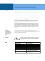
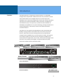
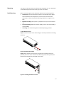
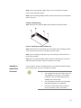
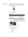
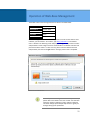
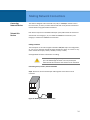
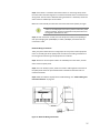
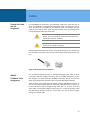
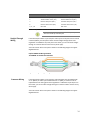
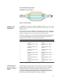
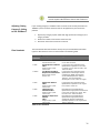
MaxiiNetTM VI3010 Installation and Getting Started Guide 10 Port Series PoE+ L2 Plus Managed Switch 2014 Vigitron, Inc. All rights reserved. All brand and product names are trademarks or registered trademarks of their respective companies. MaxiiNetTM Vi3010 Gigabit Managed Switch Installation and Getting Started Guide 2 About This Guide Purpose This guide gives specific information on how to operate and use the management functions of the switch. Audience The guide is intended for use by network administrators who are responsible for operating and maintaining network equipment. Consequently, it assumes a basic working knowledge of general switch functions, the Internet Protocol (IP), and Simple Network Management Protocol (SNMP). Conventions The following conventions are used throughout this guide to show information: NOTE: Emphasizes important information or calls your attention to related features or instructions. WARNING: Alerts you to a potential hazard that could cause personal injury. CAUTION: Alerts you to a potential hazard that could cause loss of data, or damage the system or equipment. Warranty See the Customer Support/Warranty booklet included with the product. A copy of the specific warranty terms applicable to Vigitron’s products and replacement parts can be obtained from Vigitron’s Sales and Service Office or authorized dealer. 3 Contents About This Guide ...........................................................................................................................................................3 Compliances and Safety Statements .............................................................................................................................5 Introduction ...................................................................................................................................................................8 Description of Hardware ..............................................................................................................................................10 Network Planning ........................................................................................................................................................12 Installing the Switch .....................................................................................................................................................15 Operation of Web-Base Management .........................................................................................................................22 Making Network Connections .....................................................................................................................................24 Cable Labeling and Connection Records ......................................................................................................................29 Troubleshooting ...........................................................................................................................................................30 Power and Cooling Problems .......................................................................................................................................32 Cables ..........................................................................................................................................................................33 Specifications ...............................................................................................................................................................37 Compliances ................................................................................................................................................................39 Warranty ......................................................................................................................................................................42 Contact Information ....................................................................................................................................................43 4 Compliances and Safety Statements FCC-Class A This equipment has been tested and found to comply with the limits for a Class A computing device pursuant to Subpart J of part 15 of FCC Rules, which are designed to provide reasonable protection against such interference when operated in a commercial environment. This equipment generates, uses, and can radiate radio frequency energy and if not installed and used in accordance with the instruction manual, may cause harmful interference to radio communications. Operation of this equipment in a residential area is likely to cause harmful interferences in which case the user will be required to correct the interferences at his own expense. You are cautioned that changes or modifications not expressly approved by the party responsible for compliance could void your authority to operate the equipment. You may use unshielded twisted-pair (UTP) for RJ-45 connections - Category 3 or better for 10 Mbps connections, Category 5 or better for 100 Mbps connections, and Category 5, 5e, or 6 for 1000 Mbps connections. For fiber optic connections, you may use 50/125 or 62.5/125 micron multimode fiber or 9/125 micron singlemode fiber. CE Mark Declaration of Conformance for EMI and Safety (EEC) UL Mark EMC This equipment has been tested and found to comply with the protection requirements of European Emission Standard EN55022/EN61000-3 and the Generic European Immunity Standard EN55024. Ul 60950-1 Information Technology Equipment - Safety - Part 1: General Requirements - Edition 2 - Revision Date 2014/05/13 EN55022(2006)+A1:2007/CISPR 22:2006+A1:2006 IEC61000-4-2 (2001) IEC61000-4-3( 2002) IEC61000-4-4(2004) IEC61000-4-5 (2001) IEC61000-4-6 (2003) IEC61000-4-8 (2001) IEC61000-4-11(2001) Class A 4K V CD, 8KV, AD 3V/m 1KV – (power line), 0.5KV – (signal line) Line to Line: 1KV, Line to Earth: 2KV 130dBuV(3V) Level 2 1A/m Voltage dips: >95%, 0.5period, 30%, 25periods Voltage interruptions: >95%, 250periods 5 CAUTION: Circuit devices are sensitive to static electricity, which can damage their delicate electronics. Dry weather conditions or walking across a carpeted floor may cause you to acquire a static electrical charge. To protect your device, always: Touch the metal chassis of your computer to ground the static electrical charge before you pick up the circuit device. Pick up the device by holding it on the left and right edges only. If you need to use an outdoor device to connect to this device with cable, then you need to add an arrester on the cable between outdoor device and this device. Fig. Add an arrester between outdoor device and this switch Supports SFP manufactured by Vigitron and others conforming to MSA standards. Differences between manufacturers may result in difference in performance or provided information. NOTE: The switch is an indoor device. If it will be used in an outdoor environment or connected with an outdoor device, then a lightning arrester must be used to protect the switch. 6 WARNING: Self-demolition on this product is strictly prohibited. Damages caused by self-demolition will be charged for repairing fees. Do not place product outdoor or in a sandstorm. Before installation, please make sure input the power supply and product specifications are compatible to each other. To reduce the risk of electric shock. Disconnect all AC or DC power cords and RPS cables to completely remove power from the unit. Before importing / exporting configuration, please make sure the firmware version is always the same. After the firmware upgrade, the switch will remove the configuration automatically to latest firmware version. Related Publication The following publication gives specific information on how to operation and use the management functions of the switch: The User’s Manual Revision History This section summarizes the changes in each revision of this guide. 7 Introduction Overview The Vi3010 PoE switch, next generation network solutions, is an affordable managed switch that provides a reliable infrastructure for your business network. These switches deliver more intelligent features you need to improve the availability of your critical business applications, protect your sensitive information, and optimize your network bandwidth to deliver information and applications more effectively. Easy to set up and use, it provides the ideal combination of affordability and capabilities for entry level networking, including small business or enterprise application. It also helps you create a more efficient and betterconnected workforce. The Vi3010 is an easy-implement managed Ethernet switch that provides ideal flexibility to design suitable network infrastructure for business requirement. However, unlike other entry-level switching solutions that provide advance managed network capabilities only in the most expensive models, all of Vigitron’s series switches support the advanced security management capabilities and network features to support data, voice, security, and wireless technologies. These switches are easy to deploy and configure. They provide stable and quality performance network services your business needs. Power LED Console Reset/ Default Switch TP Port LEDs 10/100/1G Base-T RJ-45 Ports Switch SFP Port LEDs TP and 100/1G SFP Combo Ports Front of the Switches Back of the Switches AC Power Cord 8 Switch Architecture The switch performs a wire-speed, non-blocking switching fabric. This allows wirespeed transport of multiple packets at low latency on all ports simultaneously. The switch also features full-duplex capability on all ports, which effectively doubles the bandwidth of each connection. This switch uses store-and-forward technology to ensure maximum data integrity. With this technology, the entire packet must be received into a buffer and checked for validity before being forwarded. This prevents errors from being propagated throughout the network. Network Management Options The switch can also be managed over the network with a web browser or a Telnet application. The switch includes a built-in network management agent that allows it to be managed in-band by using SNMP or RMON (Groups 1, 2, 3, 9) protocols. It also has an RJ-45 console port connector on the front panel for out-of-band management. A PC may be connected to this port for configuration and monitoring out-of-band via a null-modem serial cable (see Appendix B for wiring options). NOTE: For a detailed description of the management features, refer to the user’s manual. 9 Description of Hardware 1000Base-T Ports The switch contains 8/10 1000BASE-T RJ-45 ports. All RJ-45 ports support automatic MDI/MDI-X operation, auto-negotiation, and IEEE 802.3x autonegotiation of flow control, so the optimum data rate, and transmission can be selected automatically. SFP Transceiver Slots Vi3010 supports the Small Form Factor Pluggable (SFP) transceiver slots. The SFP transceiver slots are shared with RJ-45 port 9 to 10. In the default configuration, if a SFP transceiver (purchased separately) is installed in a slot and has a valid link on the port, the associated RJ-45 port is disabled. The following table shows a list of transceiver types which have been tested with the switch. For an updated list of vendors supplying these transceivers, contact your local dealer. For information on the recommended standards for fiber optic cabling, see “1000 Mbps Gigabit Ethernet Collision Domain” on page 27. Media Standard Fiber Diameter (microns) 50/125 62.5/125 Wavelength (nm) Maximum Distance* 850 850 550 m 275 m 9/125 1310 10 km 9/125 1550 30.50 km 9/125 1300 10 km 1000BASE-LX Single Fiber N/A TX-1310/RX-1550 20 km Tx-1550/RX-1310 20 km 1000BASE-T N/A N/A 100 m 100-FX 50/125 850 2 km 62.5/125 1550 15km 1000BASE-SX 1000BASE-LX/ LHX/ XD/ZX Table 1: Supported SFP Transceivers NOTE: *Maximum distance may vary for different SFP vendors. 10 Port and System Status LEDs The Vi3010 has a display panel for system and port indications that simplify installation and network troubleshooting. The LEDs are located on left hand side of the front panel for easy viewing. Details are shown below and described in the following tables. LED Conditions Status TP (Link/ACT) Green Green when the TP link is good. Blinks when any traffic is present. PoE Green Green when the port is delivering PoE power. SFP (Link/ACT) Green/Amber Green when the SFP link is 1000Mp/s. Amber when the SFP link is 100Mb/s. Blinks when any traffic is present. Table 2: Port Status LEDs SYSTEM LED Condition Status Power Green OFF Lit when power is coming up Table 3: System Status LED Power Supply Socket There is a power socket in the rear panel of the switch. For normal power supply, the Vi3010 8/10/12-Port series switch has a standard power socket for AC power cord. Figure 3: AC Power Supply Socket 11 Network Planning Introduction to Switching A network switch allows simultaneous transmission of multiple packets. It can partition a network more efficiently than bridges or routers. Therefore, the switch has been recognized as one of the most important devices for today’s networking technology. When performance bottlenecks are caused by congestion at the network access point such as file server, the device can be connected directly to a switched port. By using the full-duplex mode, the bandwidth of the dedicated segment can be doubled to maximize throughput. When networks are based on repeater (hub) technology, the distance between end stations is limited by a maximum hop count. However, a switch can subdivide the network into smaller and more manageable segments, and link them to the larger network. It then turns the hop count back to zero and removes the limitation. A switch can easily be configured in any Ethernet, Fast Ethernet, or Gigabit Ethernet network to significantly increase bandwidth while using conventional cabling and network cards. Application Examples The Vi3010 has auto MDIX and 2 slots for the removable SFP module which support comprehensive types of fiber connection, such as LC and BiDi-LC modules. It is not only designed to segment your network, but also to provide a wide range of options in setting up network connections. Some typical applications are described below. The switch is suitable for the following applications: Remote site application is used in enterprise or SMB. Peer-to-peer application is used in two remote offices. Office network. High performance requirement environment. Advance security for network safety application. Suitable for data/voice and video conference application. 12 Vi3026 Vi3026 Figure 4: Network Connection between Remote Site and Central Site Vi3026 Figure 5: Peer-to-peer Network Connection 13 Vi3026 Figure 6: Office Network Connection 14 Installing the Switch Selecting a Site The switch can be mounted in a standard 19 inch equipment rack by using the rack mount kit or on a flat surface. Be sure to follow the guidelines below when choosing a location. The site should: o Be at the center of all the devices that you want to link and near a power outlet. o Be able to maintain its temperature within 0°C to 40°C (32°F to 104°F) and its humidity within 10% to 90%, non-condensing. o Be accessible for installing, cabling, and maintaining the devices. o Allow the status LEDs to be clearly visible. Make sure the twisted-pair Ethernet cable is always routed away from power lines, radios, transmitters, or any other electrical interference. Make sure that Vi3010 is connected to a separate grounded power outlet that provides 100 to 240 VAC, 50 to 60 Hz. Ethernet Cabling To ensure proper operation when installing the switch into a network, make sure that the current cables are suitable for 100BASE-TX or 1000BASE-T operation. Check the following criteria against the current installation of your network: Cable type: Unshielded twisted pair (UTP) or shielded twisted pair (STP) cable with RJ-45 connectors; Category 5 or Category 5e with maximum length of 100 meters is recommend 100BASE-TX, and Category 5e or 6 with maximum length of 100 meters is recommend for 1000BASE-T. Protection from radio frequency interference emissions. Electrical surge suppression. Separation of electrical wires and data based network wiring. Safe connections with no damaged cables, connectors, or shields. 15 Figure 7: RJ-45 Connections Figure 8: SFP Transceiever Equipment Checklist After unpacking the switch, please check the contents make sure you have received all of the components. Also make sure you have all other necessary installation equipment before beginning the installation process. Package Contents Vi3010 GbE Management Switch Four Adhesive Rubber Feet AC Power Cord RS-232 to RJ-45 Console Cable NOTE: Please notify your sales representative immediately if any of the aforementioned items is missing or damaged. WARNING: The mini-GBICs are Class 1 laser devices. Avoid direct eye exposure to the beam coming from the transmit port. 16 Mounting The switch can be mounted in a standard 19 inch equipment rack, on a desktop, or a shelf. Mounting instructions for each type of site is as follows. Rack Mounting Before rack mounting the switch, please pay attention to the following factors: Temperature: Since the temperature within a rack assembly may be higher than the ambient room temperature, make sure the rack-environment temperature is within the specified operating temperature range of 0°C to 40°C. Mechanical Loading: Do not place any equipment on top of a rack-mounted unit. Circuit Overloading: Make sure that the supply circuit to the rack assembly is not overloaded. Grounding: Rack-mounted equipment should be properly grounded. To Rack-Mount Devices: Step1. Attach the brackets to the device using the screws provided in the mounting accessory. Figure 9: Attaching the Brackets Step2. Mount the device to the rack by using four rack-mounting screws (not provided). Be sure to secure the lower rack-mounting screws first to prevent the brackets from being bent by the weight of the switch. Figure 10: Installing the Switch in a Rack 17 Step3. If you’re only installing a single switch, turn to “Connection to a Power Source” at the end of this chapter. Step4. If you’re installing multiple switches, mount them in the rack, one below the other in any order. Desktop or Shelf Mounting: Step1. Attach the four adhesive rubber feet to the bottom of the first switch. Figure 11: Attaching the Adhesive Rubber Feet Step2. Set the device on a flat surface near an AC power source, making sure there are at least two inches of space on all sides for proper air flow. Step3. If you’re installing a single switch, go to “Connecting to a Power Source” at the end of this Chapter. Step4. If you’re installing multiple switches, attach four adhesive feet to each one. Place each device squarely on top of the one below, in any order. Installing an Optional SFP Transceiver You can install or remove a mini-GBIC SFP from a mini-GBIC slot without having to power off the switch. Use only manufacture mini-GBIC. NOTE: The mini-GBIC slots are shared with the two 10/ 100/ 1000Base-T RJ-45 ports. If a mini-GBIC is installed in a slot, the associated RJ-45 port is disabled and cannot be used. The mini-GBIC ports operate only at full duplex. Half duplex operation is not supported. Ensure the network cable is NOT connected when you install or remove a mini-GBIC. 18 CAUTION: Use only supported genuine manufacture miniGBICs with your switch. Non-manufacture mini-GBIC might have compatibility issues, and may result in product malfunction. Figure 12: Inserting an SFP Transceiver into a Slot The SFP slots support the following optional SFP transceivers: Description 1000Base-SX GE SFP Fiber Module, LC Multi-Mode 850nm 1000Base-SX GE SFP Fiber Module, LC Multi-Mode 1310nm 2km 1000Base-LX GE SFP Fiber Module, LC Single-Mode 10km 1000Base-LX GE SFP Fiber Module, LC Single-Mode 30km 1000Base-LX GE SFP Fiber Module, LC Single-Mode 50km 1000Base-LX GE SFP Fiber Module, LC Single-Mode 50km 1000Base-LX GE SFP Fiber Module, Bidi LC Single-Mode 10km, 1310nm 1000Base-LX GE SFP Fiber Module, Bidi LC Single-Mode 10km, 1550nm 1000Base-LX GE SFP Fiber Module, Bidi LC Single-Mode 20km, 1550nm 1000Base-LX GE SFP Fiber Module, Bidi LC Single-Mode 20km, 1310nm 100Base-FX FE SFP Fiber Module, LC Multi-Mode 100Base-FX FE SFP Fiber Module, LC Single-Mode 20km CAUTION: Differences in manufacturers may result in different performance and reporting status. 19 To Install a SFP Transceiver, Do the Following: Step1. Consider the network and cabling requirements to select an appropriate SFP transceiver type. Step2. Insert the transceiver with the optical connector facing outward and the slot connector facing down. Note that SFP transceivers are keyed so they can only be installed in one orientation. Step3. Slide the SFP transceiver into the slot until it clicks into place. NOTE: SFP transceivers are not provided in the switch package. Connecting to a Power Source You can plug or remove the power cord from the AC power socket to switch the power on and off. Figure 13: Inserting the Power Cord to AC Power Socket Step1. Insert the power cable plug directly into the AC socket located at the back of the switch. Step2. Plug the other end of the cable into a grounded 3-Pin AC power source. Step3. Check the front-panel LEDs as the device is powered on to be sure the POWER LED is lit. If not, check that the power cable is correctly plugged in. WARNING: For international use, you may need to change the AC line cord. You must use a line cord set that has been approved for the socket type in your country. 20 Connecting to the Console Port The RJ-45 serial port on the switch’s front panel is used to connect to the switch for out-of-band console configuration. The command-line-driven configuration program can be accessed from a terminal or a PC running a terminal emulation program. The pin assignments used to connect to the serial port are provided in the following table. 2 TXD 5 GND 3 RXD Figure 14: Serial Port (RJ-45) Pin-Out Wiring Map for Serial Cable Switch’s 8-Pin Serial Port Null Modem PC’s 9-Pin DTE Port 2 RXD (receive data) ----------------- 3 TXD (transmit data) 3 RXD (receive data) ------------------ 2 RXD (receive data) 5 SGND (Signal ground) -------------------- 5 SGND (Signal ground) Table 4: Serial Cable Wiring NOTE: No other pins are used. Figure 15: Plug in the Console Port The serial port’s configuration requirements are as follows: Default Baud Rate: 115,200 Bps Character Size: 8 Characters Parity: None Stop Bit: One Data Bits: 8 Flow Control: None 21 Operation of Web-Base Management The default values of the managed switch are listed in the table below: IP Address 192.168.1.1 Subnet Mask 255.255.255.0 Default Gateway 192.168.1.254 Username admin Password After the managed switch finished the configuration in the CLI via the switch’s serial interface, you can browse it. For instance, type http://192.168.1.1 in the address row in a browser. The following screen will pop up, asking you to input the username and password in order to login and access authentication. The default username and password are both “admin”. For first time use, please enter the default username and password, then click the <Login> button. The login process now is completed. The server 192.168.20.15 at Vi3010 requires a username and password. Vi3010 Web User Interface NOTE: If you need to configure the function or parameter, please refer to the details in the User’s Guide. You could also access the switch by clicking on "Help" under the web GUI. The switch will pop up the simple help content to guide you through setting up the parameters. 22 Vi3010 Web Help Function 23 Making Network Connections Connecting Network Devices The switch is designed to be connected to 10, 100, or 1000Mbps network cards in PCs and servers, as well as, to other switches and hubs. It may also be connected to remote devices using optional SFP transceivers. Twisted-Pair Devices Each device requires an unshielded twisted-pair (UTP) cable with RJ-45 connectors at both ends. Use Category 5, 5e, or 6 cable for 1000BASE-T connections, and Category 5 or better for 100BASE-TX connections. Cabling Guidelines The RJ-45 ports on the switch support automatic MDI/MDI-X pin-out configuration, so you can use standard straight-through twisted-pair cables to connect to any other network device (PCs, servers, switches, routers, or hubs). See Appendix B for further information on cabling. CAUTION: Do not plug a phone jack connector into an RJ-45 port. This will damage the switch. Use only twisted-pair cables with RJ-45 connectors that conform to FCC standards. Connecting to PCs, Servers, Hubs and Switches Step1. Attach one end of a twisted-pair cable segment to the device’s RJ-45 connector. Figure 16: Making Twisted-Pair Connections 24 Step2. If the device is a network card and the switch is in the wiring closet, attach the other end of the cable segment to a modular wall outlet that is connected to the wiring closet. See the section “Network Wiring Connections.” Otherwise, attach the other end to an available port on the switch. Make sure each twisted pair cable does not exceed 100 meters (328 ft) in length. NOTE: Avoid using flow control on a port connected to a hub, unless it is actually required to solve a problem. Otherwise, back pressure jamming signals may degrade overall performance for the segment attached to the hub. Step3. As each connection is made, the Link LED (on the switch) corresponding to each port will light green (1000 Mbps) or amber (100 Mbps) to indicate that the connection is valid. Network Wiring Connections Today, the punch-down block is an integral part of many of the newer equipment racks. It is actually part of the patch panel. Instructions for making connections in the wiring closet with this type of equipment are as follows. Step1. Attach one end of a patch cable to an available port on the switch, and the other end to the patch panel. Step2. If it’s not already in place, attach one end of a cable segment to the back of the patch panel where the punch-down block is located and the other end to a modular wall outlet. Step3. Label the cables to simplify future troubleshooting. See “Cable Labeling and Connection Records” on page 29. Figure 17: Network Wiring Connections 25 Fiber Optic SFP Devices An optional Gigabit SFP transceiver can be used as a backbone connection between switches, or as a connection to a high-speed server. Each single-mode fiber port requires 9/125 micron single-mode fiber optic cable with an LC connector at both ends. Each multimode fiber optic port requires 50/125 or 62.5/125 micron multimode fiber optic cabling with an LC connector at both ends. WARNING: This switch uses lasers to transmit signals over fiber optic cable. The lasers are inherently eye safe in normal operation. However, the user should never look directly at a transmit port when it is powered on. WARNING: Considering safety, when selecting a fiber SFP device, please make sure that it can function at a temperature that is not less than the recommended maximum operational temperature of the product. You must also use an approved laser SFP transceiver. Step1. Remove and keep the LC port’s rubber plug. When it’s not connected to a fiber cable, the rubber plug should be replaced to protect the optics. Step2. Check that the fiber terminators are clean. You can clean the cable plugs by wiping them gently with a clean tissue or cotton ball moistened with a little ethanol. Dirty fiber terminators on fiber optic cables will impair the quality of the light transmitted through the cable and lead to degraded performance on the port. Step3. Connect one end of the cable to the LC port on the switch and the other end to the LC port on the other device. Since LC connectors are keyed, the cable can be attached in only one orientation. Figure 18: Making Fiber Port Connections Step4. As a connection is made, check the Link LED on the switch corresponding to the port to be sure that the connection is valid. The fiber optic ports operate at 1 Gbps. The maximum length for fiber optic cable operating at Gigabit speed will depend on the fiber type as listed under “1000 Mbps Gigabit Ethernet Collision Domain” on page 27. 26 Connectivity Rules When adding hubs to your network, please note that because switches break up the path for connected devices into separate collision domains, you should not include the switch or connected cabling in your calculations for cascade length involving other devices. 1000Base-T Cable Requirements All Category 5 UTP cables that are used for 100BASE-TX connections should also work for 1000BASE-T, provided that all four wire pairs are connected. However, it is recommended that for all critical connections, or any new cable installations, Category 5e or Category 6 cable should be used. The Category 5e and 6 specifications include test parameters that are only recommendations for Category 5. Therefore, the first step in preparing the existing Category 5 cable to run 1000BASE-T is to make sure that it complies with the IEEE 802.3-2005 standards. 1000 Mbps Gigabit Ethernet Collision Domain Cable Type Maximum Cable Length Connector Category 5, 5e or 6 100-ohm UTP or STP 100.m (328 ft) RJ-45 Table 5: Maximum 1000BASE-T Gigabit Ethernet Cable Length Fiber Size Fiber Bandwidth Maximum Cable Length Connector 62.5/125 micron multimode fiber 160 MHz/km 220 m (722 ft) LC 200 MHz/km 275 m (902 ft) LC 50/125 micron multimode fiber 400 MHz/km 500 m (1641 ft) LC 500 MHz/km 550 m (1805 ft) LC Table 6: Maximum 1000BASE-SX Gigabit Fiber Cable Lengths Fiber Size Fiber Bandwidth Maximum Cable Length Connector 9/125 micron single-mode fiber 1310nm N/A 10km (6.2 miles) LC 9/125 micron single-mode fiber 1550nm N/A 30km (18.64 miles) LC 50km (31.06 miles) LC Table 7: Maximum 1000BASE-LX/LHX/XD/ZX Gigabit Fiber Cable Length Fiber Size Fiber Bandwidth Maximum Cable Length Connector Single-mode N/A 20km (12.42miles) BIDI TX-1310nm LC RX-1550nm Single-mode TX-1550nm N/A 20km (12.42miles) BIDI LC RX-1310nm Table 8: Maximum 1000BASE-LX Single Fiber Gigabit Fiber Cable Length 27 100 Mbps Fast Ethernet Collision Domain Cable Type Maximum Cable Length Connector Category 5, 5e or 6 100-ohm UTP or STP 100.m (328 ft) RJ-45 Table 9: Maximum Fast Ethernet Cable Lengths 28 Cable Labeling and Connection Records When planning a network installation, it is essential to label the opposing ends of cables and record where each cable is connected. This will allow the user to easily locate inter-connected devices, isolate faults, and change the topology without the need for unnecessary time consumption. To best manage the physical implementations of your network, follow these guidelines: Clearly label the opposing ends of each cable. Use your building’s floor plans to draw a map of the locations of all network-connected equipment. For each piece of equipment, identify the devices to which it is connected. Note the length of each cable and the maximum cable length supported by the switch ports. For ease of understanding, use a location-based key when assigning prefixes to your cable labeling. Use sequential numbers for cables that originate from the same equipment. Differentiate between racks by naming accordingly. Label each separate piece of equipment. Display a copy of your equipment map, including keys to all abbreviations at each equipment rack. 29 Troubleshooting Basic Troubleshooting Tips Most problems are caused by the following situations. Check for these items first when starting your troubleshooting: Connecting to devices that have a fixed full-duplex configuration. The RJ-45 ports are configured as “Auto”. When connecting to the attached devices, the switch will operate in one of two ways to determine the link speed and the communication mode (half-duplex or full-duplex): o If the connected device is also configured to “Auto”, the switch will automatically negotiate both link speed and communication mode. o If the connected device has a fixed configuration (e.g. 100Mbps at half or full duplex), the switch will automatically sense the link speed but will default to a communication mode of half-duplex. Because the series Vi3010 behave in this way (in compliance with the IEEE802.3 standard), if a device connected to the switch has a fixed configuration at full duplex, the device will not connect correctly to the switch. The result will be high error rates and very inefficient communications between the switch and the device. Make sure all devices connected to the Vi3010 are configured to auto negotiate, or are configured to connect at half-duplex (e.g. all hubs are configured this way). Faulty or loose cables. Look for loose or faulty connections. If they appear to be OK, make sure the connections are snug. If that does not correct the problem, try a different cable. Non-standard cables. Non-standard and miswired cables may cause network collisions and other network problems, and can seriously impair network performance. Use a new correctly-wired cable for pin-outs and correct cable wiring. A category 5 cable tester is a recommended tool for every 100Base-TX and 1000Base-T network installation. Improper Network Topologies. It is important to make sure you have a valid network topology. If you no longer experience the problems, the new topology is probably at fault. In addition, you should make sure that your network topology contains no data path loops. Check the port configuration. A port on your switch may not be operating as you expect because it has been put into a “blocking” state by the Spanning Tree, the GVRP (automatic VLANs), or the LACP (automatic trunking). Note that the normal operation of the Spanning Tree, GVRP, and LACP features may put the port into a blocking state. Or, the port just may have been configured as “Disabled” through software. 30 Symptom Action POWER LED is Off Check connections between the switch, the power cord, and the wall outlet. Contact your dealer for assistance. Verify that the switch and attached device are powered on. Be sure the cable is plugged into the switch and corresponding device. If the switch is installed in a rack, check the connections to the punch-down block and the patch panel. Verify that the proper cable type is used and its length does not exceed specified limits. Check the adapter on the attached device and cable connections for possible defects. Replace the defective adapter or cable if necessary. Link LED is Off Table 10: Troubleshooting Chart 31 Power and Cooling Problems Installation If the power indicator does not turn on when the power cord is plugged in, you may have a problem with the power outlet, power cord, or internal power supply. However, if the unit powers off after running for a while, check for loose power connections, power losses, or surges at the power outlet. If you still cannot isolate the problem, the internal power supply may be defective. Verify that all system components have been properly installed. If one or more components appear to be malfunctioning (e.g. the power cord or network cabling), test them in an alternate environment where you are sure that all the other components are functioning properly. In-Band Access You can access the management agent in the switch from anywhere within the attached network using Telnet, a web browser. However, you must first configure the switch with a valid IP address, subnet mask, and default gateway. If you have trouble establishing a link to the management agent, check to see if you have a valid network connection. Then verify that you’ve entered the correct IP address. Also, be sure the port that you are connecting to the switch has not been disabled. If it has not been disabled, then check the network cabling that runs between your remote location and the switch. NOTE: The management agent accepts up to four simultaneous Telnet sessions. If the maximum number of sessions already exists, an additional Telnet connection will not be able to log into the system. 32 Cables Twisted-Pair Cable and Pin Assignment For 10/100BASE-TX connections, the twisted-pair cable must have two pairs of wires. For 1000BASE-T connections the twisted-pair cable must have four pairs of wires. Each wire pair is identified by two different colors. For example, one wire might be green and the other, green with white stripes. Also, an RJ-45 connector must be attached to both ends of the cable. CAUTION: DO NOT plug a phone jack connector into any RJ45 port. Use only twisted-pair cables with RJ-45 connectors that conform with FCC standards. CAUTION: Each wire pair must be attached to the RJ-45 connectors in a specific orientation. The figure below illustrates how the pins on the RJ-45 connector are numbered. Be sure to hold the connectors in the same orientation when attaching the wires to the pins. Figure 19: RJ-45 Connector Pin Numbers 10BASET/100Base-Tx Pin Assignments Use unshielded twisted-pair (UTP) or shielded twisted-pair (STP) cable for RJ-45 connections: 100-ohm Category 3 or better cable for 10 Mbps connections, or 100ohm Category 5 or better cable for 100 Mbps connections. Also be sure that the length of any twisted-pair connection does not exceed 100 meters (328 feet). The RJ-45 ports on the switch base unit support automatic MDI/MDI-X operation, so you can use straight-through cables for all network connections to PCs or servers, or to other switches or hubs. In straight-through cable, pins 1, 2, 3, and 6, at one end of the cable, are connected straight through to pins 1, 2, 3, and 6 at the other end of the cable. When using any RJ-45 port on this switch, you can use either straightthrough or crossover cable. 33 Pin MDI Signal Name MDI-X Signal Name 1 Transmit Data plus (TD+) Receive Data plus (RD+) 2 Transmit Data minus (TD-) Receive Data minus (RD-) 3 Receive Data plus (RD+) Transmit Data plus (TD+) 6 Receive Data minus (RD-) Transmit Data minus (TD-) 4, 5, 7, 8 Not used Not used Table 11: 10/100BASE-TX MDI and MDI-X Port Pin outs NOTE: The “+” and “-” signs represent the polarity of the wires that make up each wire pair. Straight-Through Wiring If the twisted-pair cable is to join two ports and only one of the ports has an internal crossover (MDI-X), the two pairs of wires must be straight-through (when autonegotiation is enabled for any RJ-45 port on this switch, you can use either straightthrough or crossover cable to connect to any device type). You must connect all four wire pairs as shown in the following diagram to support Gigabit Ethernet. EIA/TIA 568B RJ-45 Wiring Standard 10/100BASE-TX Straight-through Cable Figure 20: Straight-through Wiring Crossover Wiring If the twisted-pair cable is to join two ports and either both ports are labeled with an “X” (MDI-X) or neither port is labeled with an “X” (MDI), a crossover must be implemented in the wiring (when auto-negotiation is enabled for any RJ-45 port on this switch, you can use either straight-through or crossover cable to connect to any device type). You must connect all four wire pairs as shown in the following diagram to support Gigabit Ethernet. 34 EIA/TIA 568B RJ-45 Wiring Standard 10/100BASE-TX Crossover Cable Figure 21: Crossover Wiring 1000Base-T Pin Assignments All 1000BASE-T ports support automatic MDI/MDI-X operation, so you can use straight-through cables for all network connections to PCs or servers, or to other switches or hubs. The table below shows the 1000BASE-T MDI and MDI-X port pin outs. These ports require that all four pairs of wires be connected. Note that for 1000BASE-T operation, all four pairs of wires are used for both transmit and receive. Use 100-ohm Category 5, 5e, or 6 unshielded twisted-pair (UTP) or shielded twistedpair (STP) cable for 1000BASE-T connections. Also be sure that the length of any twisted-pair connection does not exceed 100 meters (328 ft). Pin MDI Signal Name MDI-X Signal Name 1 Bi-directional Pair A Plus (BI_DA+) Bi-directional Pair B Plus (BI_DB+) 2 Bi-directional Pair A Minus (BI_DA-) Bi-directional Pair B Minus (BI_DB-) 3 Bi-directional Pair B Plus (BI_DB+) Bi-directional Pair A Plus (BI_DA+) 4 Bi-directional Pair C Plus (BI_DC+) Bi-directional Pair D Plus (BI_DD+) 5 Bi-directional Pair C Minus (BI_DC-) Bi-directional Pair D Minus (BI_DD-) 6 Bi-directional Pair B Minus (BI_DB-) Bi-directional Pair A Minus (BI_DA-) 7 Bi-directional Pair D Plus (BI_DD+) Bi-directional Pair C Plus (BI_DC+) 8 Bi-directional Pair D Minus (BI_DD-) Bi-directional Pair C Minus (BI_DC-) Table 12: 1000BASE-T MDI and MDI-X Port Pin-Outs Cable Testing for Existing Category 5 Cable Installed Category 5 cabling must pass tests for Attenuation, Near-End Crosstalk (NEXT), and Far-End Crosstalk (FEXT). This cable testing information is specified in the ANSI/TIA/EIA-TSB-67 standard. Additionally, cables must also pass test parameters for Return Loss and Equal-Level Far-End Crosstalk (ELFEXT). These tests are specified in the ANSI/TIA/EIA-TSB-95 Bulletin, “The Additional Transmission Performance Guidelines for 100 Ohm 4-Pair Category 5 Cabling.” 35 NOTE: That when testing your cable installation, be sure to include all patch cables between switches and end devices. Adjusting Existing Category 5 Cabling to Run 1000Base-T If your existing Category 5 installation does not meet one of the test parameters for 1000Base-T, there are three measures that can be applied to try and correct the problem: 1. 2. 3. Fiber Standards Replace any Category 5 patch cables with high-performance Category 5e or Catgory 6 cables. Reduce the number of connectors used in the link. Reconnect some of the connectors in the link. The International Telecommunication Union (ITU-T) has standardized various fiber types for data networks. These are summarized in the following table. ITU-T Standard Description Application G.651 Multimode Fiber 50/125-micron core Short-reach connections in the 1300nm or 850-nm band. G.652 Non-Dispersion-Shifted Fiber Single-mode, 9/125micron core Low Water Peak NonDispersion-Shifted Fiber Single-mode, 9/125micron core Longer spans and extended reach. Optimized for operation in the 1310nm band, but can also be used in the 1550-nm band. Longer spans and extended reach. Optimized for wavelength-division multiplexing (WDM) transmission across wavelengths from 1285 to 1625 nm. The zero dispersion wavelength is in the 1310-nm region. Dispersion-Shifted Fiber Single-mode, 9/125micron core 1550-nm LossMinimized Fiber Single-mode, 9/125micron core Non-Zero DispersionShifted Fiber Single-mode, 9/125micron core Longer spans and extended reach. Optimized for operation in the region from 1500 to 1600-nm. G.652.C G.653 G.654 G.655 Extended long-haul applications. Optimized for high-power transmission in the 1500 to 1600-nm region, with low loss in the 1550-nm band. Extended long-haul applications. Optimized for high-power dense wavelength-division multiplexing (DWDM) operation in the region from 1500 to 1600-nm. Table 13: Fiber Standards 36 Specifications Physical Characteristics Ports Network Interface 2 100/1000Mbps SFP Fiber ports 2 GbE Combo Port TP/ (100/1000M) SFP Ports 1-8: RJ-45 Connector 10BASE-T: RJ-45 (100-ohm, UTP cable; Category 3 or better) 100BASE-TX: RJ-45 (100-ohm, UTP cable; Category 5 or better) 1000BASE-T: RJ-45 (100-ohm, UTP or STP cable; Category 5, 5e or 6) *Maximum Cable Length - 100 m (328 ft) Ports 9-10: RJ-45 connector/ (100/1000M)SFP Buffer Architecture 1392KB on-chip frame buffer Aggregate Bandwidth 20 Gbps Switching Database LEDs 8K MAC address entries System: POWER TP Port: status (LINK/ACT), 10/100/1000M SFP Port: status (LINK/ACT/SPD), 100/1000M Weight 1.35 kg (2.97 lbs) Size 44(H) x 280(W) x 166(D)mm Temperature Operating: 0°C to 40°C (32°F to 104°F) Humidity Operating: 5% to 90% (non-condensing) Power Input 100~240VAC, 50~60Hz Power Supply Internal, auto-ranging transformer: 100 to 240 VAC, 50 to 60 Hz 20W maximum Power Consumption 37 Switch Features Forwarding Mode Throughput Store-and-forward 35.712Mpps Flow Control Full-Duplex: IEEE 802.3x Half-Duplex: Back pressure Management Features Standards In-Band Management SSH/SSL, Telnet, SNMP, or HTTP Out-Of-Band Management RS-232 (RJ-45) console port Software Loading HTTP, TFTP in-band, Console out-of-band IEEE 802.3 => 10Base-T Ethernet (Twisted-pair Copper) IEEE 802.3u => 100Base-TX Ethernet (Twisted-pair Copper) IEEE 802.3ab => 1000Base-TX Ethernet (Twisted-pair Copper) IEEE 802.3z => 1000Base-X Ethernet IEEE 802.3x => Flow Control Capability ANSI/IEEE 802.3 => Auto-negotiation IEEE 802.1Q => VLAN IEEE 802.1p => Class of Service IEEE 802.1X => Access Control IEEE 802.1D => Spanning Tree IEEE 802.1w => Rapid Spanning Tree IEEE 802.1s => Multiple Spanning Tree IEEE 802.3ad => ink Aggregation Control Protocol (LACP) IEEE 802.1AB => Link Layer Discovery Protocol (LLDP) IEEE 802.3at/af => Power Over Ethernet (PoE) Compliances Emissions EN55022 (CISPR 22) Class A EN 61000-3 FCC Class A CE Mark UL 60950-1 Immunity EN 61000-4-2/3/4/5/6/8/11 EN 55024 38 Compliances 10Base-T IEEE 802.3 specification for 10 Mbps Ethernet over two pairs of Category 3, 4, or 5 UTP cable. 100Base-T IEEE 802.3u specification for 100 Mbps Ethernet over two pairs of Category 5 UTP cable. 1000Base-LH Specification for long-haul Gigabit Ethernet over two strands of 9/125 micron core fiber cable. 1000Base-LX IEEE 802.3z specification for Gigabit Ethernet over two strands of 50/125, 62.5/125, or 9/125 micron core fiber cable. 1000Base-SX IEEE 802.3z specification for Gigabit Ethernet over two strands of 50/125 or 62.5/125 micron core fiber cable. 1000Base-T IEEE 802.3ab specification for Gigabit Ethernet over 100-ohm Category 5, 5e, or 6 twisted-pair cable (using all four wire pairs). Auto-Negotiation Signaling method allowing each node to select its optimum operational mode (e.g. speed and duplex mode) based on the capabilities of the node to which it is connected. Bandwidth The difference between the highest and lowest frequencies available for network signals. Also synonymous with wire speed, the actual speed of the data transmission along the cable. Collision Domain Single CSMA/CD LAN segment. CSMA/CD CSMA/CD (Carrier Sense Multiple Access/Collision Detect) is the communication method employed by Ethernet, Fast Ethernet, and Gigabit Ethernet. End Station A workstation, server, or other device that does not forward traffic. Ethernet A network communication system developed and standardized by DEC, Intel, and Xerox, were using baseband transmission, CSMA/CD access, logical bus topology, and coaxial cable. The successor IEEE 802.3 standard provides for integration into the OSI model and extends the physical layer and media with repeaters and implementations that operate on fiber, thin coax, and twisted-pair cable. 39 Gigabit Ethernet A 100 Mbps network communication system based on Ethernet and the CSMA/ CD access method. Transmission method that allows two network devices to transmit and receive concurrently, effectively doubling the bandwidth of that link. A 1000 Mbps network communication system based on Ethernet and the CSMA/ CD access method. IEEE Institute of Electrical and Electronic Engineers. IEEE 802.3 Defines carrier sense multiple access with collision detection (CSMA/CD) access method and physical layer specifications. Defines CSMA/CD access method and physical layer specifications for 1000BASE-T Gigabit Ethernet (now incorporated in IEEE 802.32005). Defines CSMA/CD access method and physical layer specifications for 100BASE- TX Fast Ethernet (now incorporated in IEEE 802.32005). Defines Ethernet frame start/stop requests and timers used for flow control on full-duplex links (now incorporated in IEEE 802.3-2005). Defines CSMA/CD access method and physical layer specifications for 1000BASE Gigabit Ethernet (now incorporated in IEEE 802.3-2005). Fast Ethernet Full Duplex IEEE 802.3AB IEEE 802.3U IEEE 802.3X IEEE 802.3Z IEEE 802.3at/af Lan Segment LED Local Area Network (LAN) Media Access Control (MAC) MIB Modal Bandwidth Network Diameter Defines Power Over Ethernet is used to transmit electrical power, PoE IEEE 802.3af (Class 4 PDs limited to 15.4W), PoE++ IEEE 802.3at (Class 4 PDs limited to 30W). Separate LAN or collision domain. Light emitting diode used for monitoring a device or network condition. A group of interconnected computer and support devices. A portion of the networking protocol that governs access to the transmission medium, facilitating the exchange of data between network nodes. An acronym for Management Information Base. It is a set of database objects that contains information about the device. Bandwidth for multimode fiber is referred to as modal bandwidth because it varies with the modal field (or core diameter) of the fiber. Modal bandwidth is specified in units of MHz per km, which indicates the amount of bandwidth supported by the fiber for a one km distance. Wire distance between two end stations in the same collision domain. RJ-45 Connector A connector for twisted-pair wiring. Switched Ports Ports that are on separate collision domains or LAN segments. 40 TIA Telecommunications Industry Association. Transmission Control Protocol/Internet Protocol (TCP/IP) Protocol suite that includes TCP as the primary transport protocol and IP as the network layer protocol. User Datagram Protocol (UDP) UDP provides a datagram mode for the packet-switched communications. It uses the IP as the underlying transport mechanism to provide access to IP-like services. UDP packets are delivered just like IP packets – connectionless data grams that may be discarded before reaching their targets. UDP is useful when TCP would be too complex, too slow, or just unnecessary. Unshielded twisted-pair cable. UTP Virtual LAN (VLAN) A Virtual LAN is a collection of network nodes that share the same collision domain regardless of their physical location or connection point in the network. A VLAN serves as a logical workgroup with no physical barriers, allowing users to share information and resources as though located on the same LAN. 41 Warranty Vigitron, Inc. gaurantees that all Vigitron products (“Product”), if used in accordance with these instructions, will be free of defects in material and workmanship for lifetime defined as the duration period of time until product end of life is announcement. After which, Vigitron will continue to provide warranty services for a period of 3 years. Period covering valid warranty will be determined by proof of purchase in the form of an invoice from an authorized Vigitron dealer. Warranty will only be provided for as long as the original end user purchaser owns the product. Warranty is not transferrable. At Vigitron's option, the defective product will be repaired, replaced, or substituted with a product of equal value. This warranty does not apply if, in the judgment of Vigitron, Inc., the Product fails due to damage from shipment, handling, storage, accident, abuse or misuse, or if it has been used or maintained not conforming to Product manual instructions, has been modified, or serial number removed or defaced. Repair by anyone other than Vigitron, Inc. or an approved agent will void this warranty. Vigitron, Inc. shall not under any circumstances be liable to any person for any incidental, indirect or consequential damages, including damages resulting from use or malfunction of the product, loss of profits or revenues or costs of replacement goods. The maximum liability of Vigitron, Inc. under this warranty is limited to the original purchase price of the product only. 42 Contact Information Vigitron, Inc. 7810 Trade Street, Suite 100 San Diego, CA 92121 [email protected] Tel: (858) 484-5209 Fax: (858) 484-1205 www.vigitron.com 43