1
USER MANUAL
ELECTRONICS
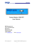
MQP Packet-Master USB12
User Manual
MQP Electronics Ltd
Unit 2, Park Road Centre
Malmesbury
Wiltshire SN16 0BX
United Kingdom
e-mail: [email protected]
Website: www.mqp.com
User Manual USB12-1.06
Copyright © 2006-7 MQP Electronics Ltd
1
USER MANUAL
ELECTRONICS
Contents
1 GETTING STARTED....................................................... 5
1.1
Introduction ............................................................................. 5
1.2 Installing the Software and Driver ......................................... 5
1.2.1 Install the Software from CD ............................................... 5
1.2.2 Installing the Driver ............................................................. 5
1.2.3 Updating the Driver ............................................................. 6
1.2.4 Update the Software ........................................................... 6
1.3
Sample Capture Files.............................................................. 6
1.4
Front and Back Panels............................................................ 7
1.5
Test Set Up .............................................................................. 9
1.6
Data Capture .......................................................................... 11
1.7
Saving the Capture................................................................ 11
2 TECHNICAL DATA ....................................................... 12
2.1
Requirements ........................................................................ 12
2.2
Specifications ........................................................................ 12
2.3
Maximum Capture File Size.................................................. 13
2.4
Safety ..................................................................................... 13
2.5
Feature Connector ................................................................ 13
2.6
External Power Supply ......................................................... 14
3 GRAPHICUSB SOFTWARE ......................................... 15
3.1
Overview ................................................................................ 15
User Manual USB12-1.06
Copyright © 2006-7 MQP Electronics Ltd
2
USER MANUAL
ELECTRONICS
3.2 Panes...................................................................................... 16
3.2.1 Event Pane........................................................................ 16
3.2.2 Analysis and Data Panes .................................................. 17
3.3 Toolbars ................................................................................. 18
3.3.1 File Functions Toolbar....................................................... 18
3.3.2 View Filter Toolbar ............................................................ 19
3.4
Capturing ............................................................................... 20
3.5
Display Filters........................................................................ 21
3.6 Search .................................................................................... 26
3.6.1 Event Search..................................................................... 26
3.6.2 Transaction Search ........................................................... 27
3.6.3 Data Search ...................................................................... 28
3.6.4 Setup Search .................................................................... 29
3.6.5 Error Search...................................................................... 30
3.7
Multiple Event Headers......................................................... 31
4 OPTION SETTINGS ...................................................... 32
4.1
File Locations ........................................................................ 32
4.2
Miscellaneous Settings......................................................... 33
4.3
Capture................................................................................... 34
5 CLASS ANALYSIS OPTIONS ...................................... 35
5.1
Registration ........................................................................... 35
5.2
Analysis Overview................................................................. 35
5.3 Vendor Class Analysis.......................................................... 38
5.3.1 Introduction ....................................................................... 38
5.3.2 File Syntax ........................................................................ 40
6 TROUBLESHOOTING .................................................. 45
User Manual USB12-1.06
Copyright © 2006-7 MQP Electronics Ltd
3
USER MANUAL
ELECTRONICS
7 WARRANTY.................................................................. 47
7.1
Warranty................................................................................. 47
7.2
Limitations ............................................................................. 47
7.3
Warranty Period..................................................................... 47
7.4
Obtaining Service.................................................................. 47
8 EXPORT FUNCTIONS .................................................. 48
8.1
Exporting Capture Events .................................................... 48
8.2 Exporting Descriptors........................................................... 49
8.2.1 Standard Descriptors ........................................................ 49
8.2.2 Class Specific Descriptors ................................................ 51
8.3
Exporting Data from a Specific Event ................................. 52
9 ERRORS ....................................................................... 53
9.1
Invalid PID .............................................................................. 53
9.2
Invalid CRC ............................................................................ 53
9.3
Invalid SOF ............................................................................ 53
9.4
Invalid Control Transfer........................................................ 53
9.5
Invalid Transaction................................................................ 54
9.6
Bit Stuffing Error ................................................................... 54
9.7
Byte Error............................................................................... 54
9.8
Spurious Data ........................................................................ 54
9.9
Both Lines High..................................................................... 54
9.10
Spurious End of Packet..................................................... 54
User Manual USB12-1.06
Copyright © 2006-7 MQP Electronics Ltd
4
USER MANUAL
ELECTRONICS
1 GETTING STARTED
1.1 Introduction
The Packet-Master USB12 is a non-intrusive Hardware USB Bus
Analyser, intended for development of Low and Full Speed USB
devices and hubs etc. It comes complete with our Windows
application GraphicUSB for capturing and displaying every detail of
the data interactions on a USB link.
1.2 Installing the Software and Driver
1.2.1 Install the Software from CD
• Insert the Installation disk into the CD drive.
• The disk should auto-start.
• Follow the on screen instructions.
• If the disk doesn’t start then run the file Setup.exe in the root
directory of the CD.
• If you should have problems with the install disk, you can run the
installation file directly from its location on the CD. If the CD drive is
drive “D:” the file is located in: “D:\website\” and is called
“usb12_setup.exe”.
1.2.2 Installing the Driver
• The first time you plug in the USB cable from your Packet-Master
USB12, Windows will start the “Found new Hardware” wizard. If it
asks to search “Windows Update”, select “No, not this time”.
• Ensure that you have the Installation CD in a CD drive. (if the CD
auto-runs and starts the GraphicUSB installation screen, then click
“Exit” to leave it before continuing with the driver installation.)
• For your information: If the CD drive is drive “D:”, the driver files are
located in “D:\Drivers\” and the installation file is called
“mqpuba.inf”.
User Manual USB12-1.06
Copyright © 2006-7 MQP Electronics Ltd
5
USER MANUAL
ELECTRONICS
1.2.3 Updating the Driver
• If there is a requirement to update the USB Driver for the PacketMaster USB12, you will be informed when you run a new version of
GraphicUSB.
• Should you need to update the USB Driver at any time, full
instructions are given in the file:
“C:\Program Files\MQP Electronics\GraphicUSB\usb
drivers\updating.txt”
(Assuming a default location for the GraphicUSB installation)
• The driver itself is located in:
“C:\Program Files\MQP Electronics\GraphicUSB\usb drivers\”
(Assuming a default location for the GraphicUSB installation)
1.2.4 Update the Software
If at a later date you wish to make use of an update from our
website. Please follow the instructions below:
• Download the file.
• Run the down-loaded .exe file straight from your hard disk and
follow the on screen instructions.
• The latest version of the software is available at
http://www.mqp.com/
1.3 Sample Capture Files
During installation of the software a number of sample capture files
will be placed in the folder “Samples” in the application’s installation
directory. If you have accepted the defaults during installation, this
will be called:
C:\Program Files\MQP Electronics\GraphicUSB\Samples
The sample files have the extension *.mqu
You may find it helpful to open one of these sample files to become
familiar with the capabilities of GraphicUSB.
User Manual USB12-1.06
Copyright © 2006-7 MQP Electronics Ltd
6
USER MANUAL
ELECTRONICS
1.4 Front and Back Panels
• The Power Indicator illuminates when the Packet-Master is
powered and connected to the Host computer.
• The Activity indicator shows the presence of data exchanges. The
indicator flashes once for each DATA0, DATA1 or SETUP packet.
• Capture Start and Capture Stop buttons control the capturing of
USB data, and the Capture Indicator shows when capturing is in
progress.
• The USB through-connectors are used for connection to the Host
and device under test.
User Manual USB12-1.06
Copyright © 2006-7 MQP Electronics Ltd
7
USER MANUAL
ELECTRONICS
• The Packet-Master is normally USB Bus Powered for convenience
of use.
• An optional external power input is provided (this is not normally
required, but useful if the host won’t configure a high-power device)
• A High Speed USB (480 Mbit/s) provides the connection to the
Host PC.
• A 10 pin Feature connector provides signals for an oscilloscope or
logic analyser.
User Manual USB12-1.06
Copyright © 2006-7 MQP Electronics Ltd
8
USER MANUAL
ELECTRONICS
1.5 Test Set Up
To achieve a good capture rate it is important to provide a suitable
test environment. The Packet-Master USB12 should preferably be
hosted by a good performance PC with a high speed USB connection.
The USB host controller should not be shared by any other USB
device while doing the testing.
The Packet-Master USB12 will function correctly when connected
to a Full Speed link but the capacity will be severely reduced and only
low rates of USB traffic may be captured from the device under test.
In a similar fashion it is theoretically possible to use the same host
computer for the Packet-Master USB12 and for the Host under Test.
We do not recommend this, but if it is absolutely unavoidable, then
you must at least use a separate USB host controller for the device
under test. If your computer does not have two host controllers then
you will need to buy a plug-in USB host controller card.
User Manual USB12-1.06
Copyright © 2006-7 MQP Electronics Ltd
9
USER MANUAL
ELECTRONICS
It is possible to have more than one device under test. In this case
the devices must first be connected to a Hub and the Hub plugged
into the Packet-Master. Both devices and the Hub are downstream of
the Packet-Master.
It is not recommended that a Hub is connected upstream of the
analyser as traffic from the Host to Hub may be recorded but not the
traffic from the Hub to the Host.
This test equipment, by its very nature, has to connect to a junction
of two USB cables in order to probe the data on the link. It is
important to keep the cables between the ‘device under test’ and the
‘host under test’ as short as possible (for example 1m), and to use
good quality cables.
User Manual USB12-1.06
Copyright © 2006-7 MQP Electronics Ltd
10
USER MANUAL
ELECTRONICS
1.6 Data Capture
• Connect the Packet-Master to the Host computer as shown in the
Test Set Up section. You must first have installed the GraphicUSB
software and Driver.
• Connect the Device under Test and the Host under Test as shown
in the Test Set UP section. It may be preferable to use a simple
working commercial device such as a low speed mouse for your
first data capture.
• Run the GraphicUSB software.
• Start capturing by either momentarily pressing the Start button on
the Packet-Master front panel or clicking Capture on the tool bar.
• A capture window will open and you should see the capture
statistics incrementing.
• After a few moments stop capturing by either momentarily pressing
the Stop Button on the Packet-Master front panel or clicking the
Save button in the Capture window.
• A full analysis of the data captured will be displayed.
• Each new capture will create a new capture window. To select the
capture you wish to view click on “Window” on the menu bar.
1.7 Saving the Capture
If you wish to keep the capture for future reference, click on
“File…Save” on the menu bar or on the “Save” icon on the Tool Bar.
By default, files will be saved in the folder specified in the Options
Settings Window. GraphicUSB files have the extension .mqu
User Manual USB12-1.06
Copyright © 2006-7 MQP Electronics Ltd
11
USER MANUAL
ELECTRONICS
2 TECHNICAL DATA
2.1 Requirements
The minimum requirements for the Packet-Master Host are as
follows:
• Pentium 3 - 600MHz
• PC with High Speed USB port should be dedicated to the capturing.
(Actual target device should be connected to a different Host
Computer to ensure reliable capture bandwidth)
• Windows XP (Service Pack 1 or better) preferred. Also Windows
2000 / ME / 98SE.
• CD ROM / DVD Drive
• 128MB RAM
• 100MB space on Hard Disk
Note: A good performance machine is recommended for good
capture rate.
2.2 Specifications
Weight:
165 g
Dimensions:
129 x 100 x 31 mm
Temperature:
0°C - 40°C
Humidity:
20% - 80% non condensing
Power:
150mA from USB host
Optionally zero mA from USB if
powered externally
User Manual USB12-1.06
Copyright © 2006-7 MQP Electronics Ltd
12
USER MANUAL
ELECTRONICS
2.3 Maximum Capture File Size
The maximum size of the Capture file is limited by the available
RAM in the Host computer.
2.4 Safety
CE compliant.
2.5 Feature Connector
The signals available on the back panel connector are:
Pin
Signal
1
D+
2
GND
3
D-
4
GND
5
DECODED DATA
6
GND
7
8
9
10
Notes
De-glitched and synchronised
with the 48 or 6MHz clock
De-glitched and synchronised
with the 48 or 6MHz clock
Decoded NRZI data
DATA CLOCK ENABLE Data sampling signal phase-
locked to the incoming signal
transitions
GND
PACKET SYNC PULSE A pulse one clock period wide
indicating that the sync pattern
has been detected
GND
User Manual USB12-1.06
Copyright © 2006-7 MQP Electronics Ltd
13
USER MANUAL
ELECTRONICS
2.6 External Power Supply
The Packet-Master USB12 normally derives its power from the
Host computer's USB connection, but may be powered externally.
This is not normally required, but useful if the host won’t configure a
high-power device. The external supply must meet the following
requirements:
Output Voltage
9V Regulated
Output Current
300mA
Polarity
Centre Pin Positive
•
A suitable Power Supply is available from MQP Electronics Ltd.
The use of any other supply is not recommended and is at the users
own risk.
User Manual USB12-1.06
Copyright © 2006-7 MQP Electronics Ltd
14
USER MANUAL
ELECTRONICS
3 GraphicUSB SOFTWARE
3.1 Overview
The Packet-Master USB12 owes a large part of its functionality to
the GraphicUSB application, which is supplied with the Analyser. A
simple, yet information-rich display allows you to view every detail of
a capture.
This shows the organization of the screen after a typical capture:
User Manual USB12-1.06
Copyright © 2006-7 MQP Electronics Ltd
15
USER MANUAL
ELECTRONICS
3.2 Panes
3.2.1 Event Pane
The Event Pane graphically shows every detail of data and timing
on the bus. The example shown below is an IN transaction made up
of two packets. The left hand column contains an event number and a
time stamp. The time stamp has a resolution of 20.83ns. A vertical
line associates the packets within the transaction. Looking in detail at
the display for event #24 below, the following information is displayed:
• The speed of the transmission. FS is full speed, 12MHz and LS is
low speed, 1.5MHz.
• The direction of the packet. A right pointing arrow is for host to
device and a left pointing arrow for device to host.
• The Synchronisation field. The bit pattern received is shown.
• The Packet ID (PID). In this case it is an IN token.
• The Address field.
• The Endpoint field.
• The CRC field. Token packets have a five bit CRC while data
packets have a sixteen bit CRC.
• End of Packet (EOP). An EOP is made up of a single ended zero
for approximately two bit times followed by a J state. The time
shown is the length of the single ended zero.
• Finally the idle time before the next event.
An error e.g. an incorrect CRC is indicated by the appropriate field
being highlighted in red. A field highlighted in orange indicates a
potential problem or warning.
User Manual USB12-1.06
Copyright © 2006-7 MQP Electronics Ltd
16
USER MANUAL
ELECTRONICS
This view of a GraphicUSB capture shows data being transferred
at two different speeds on the same link. Each packet is preceded by
a coloured marker indicating Full Speed or Low Speed. This makes
the function of the PREAMBLE packet very clear. Notice also the
detailed timing information for Hub Setup time, End of Packet
duration, and IDLE state time.
3.2.2 Analysis and Data Panes
By clicking on an event row in the event pane, a complete analysis
of the event is displayed in the analysis pane, and the data content is
shown in its entirety in the data pane. Where appropriate, any
information selected in the analysis pane is highlighted in the data
pane for easy identification. All standard requests and descriptors are
analysed in detail. Any discrepancies are described.
User Manual USB12-1.06
Copyright © 2006-7 MQP Electronics Ltd
17
USER MANUAL
ELECTRONICS
3.3 Toolbars
3.3.1 File Functions Toolbar
Start Capture
Open an existing Capture file
Save the currently active Capture document
Print the current Events Pane (If icon is grayed out,
click in the Events Pane)
About GraphicUSB
Help on GraphicUSB
Search Settings
Find First
Find Previous
Find Next
Find Last
User Manual USB12-1.06
Copyright © 2006-7 MQP Electronics Ltd
18
USER MANUAL
ELECTRONICS
3.3.2 View Filter Toolbar
Show Start of Frame events
Show bus events
Show Transactions in Control Transfer
Show Packets
Show NAKed Transactions
Go to Event number
Go to selected Event
User Manual USB12-1.06
Copyright © 2006-7 MQP Electronics Ltd
19
USER MANUAL
ELECTRONICS
3.4 Capturing
Capturing may be started by either clicking on the Capture button
situated on the tool bar of GraphicUSB or by momentarily pressing
the Start button on the front panel. During capturing an Event
Capturing Window opens. This window contains the following
information:
• The number of packets received
• The number of ACKed transactions
• The number of NAKed transactions
• The number of frames received
• The duration of the current capture
• The size of the captured data in bytes
At any time during the capture, devices may be plugged in or out.
User Manual USB12-1.06
Copyright © 2006-7 MQP Electronics Ltd
20
USER MANUAL
ELECTRONICS
To end capturing and display the data, either click on SAVE in the
Capture window or momentarily press the STOP button on the front
panel. Clicking RESTART will clear all the events so far and start
again. Clicking CANCEL will abandon the capture.
3.5 Display Filters
Toolbar buttons allow the filtering out of events that you do not
wish to display. The following filters are available:
Show SOF
Start of Frame packets on full speed devices and Keep Alive
events on low speed devices come at approximately one millisecond
intervals. Clicking this tool bar button removes/shows these events.
Show Bus States
•
•
•
•
•
Clicking the Bus States button removes/shows the following events:
Plugged in
Unplugged
Reset
Suspend
Resume
User Manual USB12-1.06
Copyright © 2006-7 MQP Electronics Ltd
21
USER MANUAL
ELECTRONICS
Show Transactions
A Control Transfer contains a number of transactions starting with
a SETUP. Clicking this button removes/shows the transactions within
a Control Transfer. The example below shows the effect of filtering
out the transactions.
Show Transactions
Hide Transactions
User Manual USB12-1.06
Copyright © 2006-7 MQP Electronics Ltd
22
USER MANUAL
ELECTRONICS
If transactions within control transfers have been filtered out, then
double clicking on a particular control transfer will reveal the
transactions within it, as shown below.
Show Selected Transactions
User Manual USB12-1.06
Copyright © 2006-7 MQP Electronics Ltd
23
USER MANUAL
ELECTRONICS
Show Packets
A transaction contains a number of packets. Clicking this button
removes/shows the packets within the transactions.
Show Packets
Hide Packets
User Manual USB12-1.06
Copyright © 2006-7 MQP Electronics Ltd
24
USER MANUAL
ELECTRONICS
If packets have been filtered out, then double clicking on a
particular transaction will reveal the packets within it, as shown below.
Show Selected Packets
User Manual USB12-1.06
Copyright © 2006-7 MQP Electronics Ltd
25
USER MANUAL
ELECTRONICS
Show NAKs
Clicking this button removes/shows any NAKed transactions. This
differs from filtering NAKs during capture where NAKed control
transactions will always be included.
3.6 Search
The Search function is used to locate particular events within the
captured data. Events which are not currently being displayed will still
be found by the search function and the display filter settings will be
adjusted accordingly. Select the Search Settings by either clicking the
or selecting the item on the Edit menu. Items may be
Tool Button
searched for by Event, Transaction, Data, Setup or Error.
Once a search has been defined the Search Settings Window may be
closed and the Toolbar Search buttons
used instead.
This provides a clearer view of the data.
3.6.1 Event Search
The events search allows you to find such items as Reset,
Preamble etc.
User Manual USB12-1.06
Copyright © 2006-7 MQP Electronics Ltd
26
USER MANUAL
ELECTRONICS
3.6.2 Transaction Search
Transactions may be searched for according to their Type (IN,
OUT, or SETUP), the Response (ACK, NAK, STALL or NONE), the
Device Address and/or Endpoint. If no selection is made in any
particular column then any transaction meeting the requirements of
the other columns will be found.
User Manual USB12-1.06
Copyright © 2006-7 MQP Electronics Ltd
27
USER MANUAL
ELECTRONICS
3.6.3 Data Search
The data to be searched for is entered as a sequence of Hex bytes
separated by spaces. The size of the data field, the Device Address
and Endpoint Address can also be specified. The example below
shows a search for Hex bytes ‘A3 00’ in an 8 byte Data field with
Device Address 1 and Endpoint 0. If no selection is made in any
particular column then any transaction meeting the requirements of
the other columns will be found.
User Manual USB12-1.06
Copyright © 2006-7 MQP Electronics Ltd
28
USER MANUAL
ELECTRONICS
3.6.4 Setup Search
The example below demonstrates a search for a bRequest of 05h
in a standard Setup to a device having Address 0 and Endpoint 0.
Masks are available if you wish to test for only a part of a field. If no
selection is made in any particular column then any transaction
meeting the requirements of the other columns will be found.
User Manual USB12-1.06
Copyright © 2006-7 MQP Electronics Ltd
29
USER MANUAL
ELECTRONICS
3.6.5 Error Search
Errors such as Invalid PID, Invalid CRC etc may be found by
selecting the appropriate boxes. A more detailed explanation of these
errors is given in the Errors Chapter.
User Manual USB12-1.06
Copyright © 2006-7 MQP Electronics Ltd
30
USER MANUAL
ELECTRONICS
3.7 Multiple Event Headers
Numerous consecutive Start of Frame packets or Keep Alive
events make the display difficult to read. GraphicUSB inserts multiple
Event Headers before such sequences. The packets can be hidden
by clicking on the “Show Packets” button with the multiple Events
Header still being visible. The multiple Events Headers can be hidden
by clicking on the “Show SOFs” button. The example below shows 41
SOF’s grouped together.
Show SOF Packets
Hide SOF Packets
User Manual USB12-1.06
Copyright © 2006-7 MQP Electronics Ltd
31
USER MANUAL
ELECTRONICS
4 OPTION SETTINGS
Select Options in the Edit menu to open the Option Settings
Window.
4.1 File Locations
Use this to specify the locations of the Capture and temporary files.
User Manual USB12-1.06
Copyright © 2006-7 MQP Electronics Ltd
32
USER MANUAL
ELECTRONICS
4.2 Miscellaneous Settings
• User warnings e.g. concerning the test set-up, may be re-enabled.
• If several captures are to be done in a row without the need to save
each capture, then it can be beneficial to check the box 'Abandon
previous file on new capture'. This will save RAM and make
shutting down GraphicUSB quicker.
User Manual USB12-1.06
Copyright © 2006-7 MQP Electronics Ltd
33
USER MANUAL
ELECTRONICS
4.3 Capture
The size of the Capture file may be minimized by filtering Start of
Frame or Keep Alive events or NAKed transactions. Please note that
NAKed control transactions will always be included in the capture.
The size of the capture buffer defaults to a safe value which should
guarantee a reliable capture under most circumstances. You may
increase this size as required, but you should be prepared to
decrease it again if you start to have poor response caused by the
system using virtual memory to satisfy your requirement. The
‘Recommend Size’ button returns the buffer size to the default value
for your system. An option well worth considering is to increase the
size of the RAM in your PC.
User Manual USB12-1.06
Copyright © 2006-7 MQP Electronics Ltd
34
USER MANUAL
ELECTRONICS
5 CLASS ANALYSIS OPTIONS
5.1 Registration
The Class Analysis Options are supplied as software add-ons for
GraphicUSB. The options are available for individual classes, so you
only need to purchase the functionality you actually require. The
options are provided in the form of 16 digit hexadecimal registration
codes.
To enable a particular option, first ensure the analyser is
connected to the host, and then click in the menu bar on
Edit…Registration… and the following dialog will appear.
Enter the registration code provided and the corresponding option
should become checked. Please store the registration code carefully
in case you need to install the option on another host computer.
5.2 Analysis Overview
The Class Analysis option you have enabled will enhance all
captures performed on the analyser in question. If you use the
User Manual USB12-1.06
Copyright © 2006-7 MQP Electronics Ltd
35
USER MANUAL
ELECTRONICS
analyser on a different host, remember to register the option on that
computer as well.
The option will not allow the analysis of classes on captures
performed with the analyser before the option was registered.
However the captured files can later be viewed in their analysed form
on any computer with or without the analyser present.
A typical class analysis example is shown below.
User Manual USB12-1.06
Copyright © 2006-7 MQP Electronics Ltd
36
USER MANUAL
ELECTRONICS
This shows a HID Report Descriptor, and below is the result of
parsing it.
Each transfer of a HID report is also analysed, as follows.
User Manual USB12-1.06
Copyright © 2006-7 MQP Electronics Ltd
37
USER MANUAL
ELECTRONICS
5.3 Vendor Class Analysis
5.3.1 Introduction
Unlike other USB classes, Vendor Class does not have a
predetermined specification. The class is made up of whatever
control requests and data transfer types a vendor finds useful. For
this reason, it is normally difficult to provide a useful analysis. MQP's
vendor class analysis option attempts to overcome this problem, by
allowing the user to specify characteristics of the vendor class which
can usefully be displayed on the capture document screens. To do
this, the vendor class analysis option must be registered.
To do this the user should provide a specification file for their
device. The file will have a predetermined file name as follows:
vendVVVVPPPP.txt
where VVVV is four hexadecimal characters defining the Vendor
ID, and PPPP is four hexadecimal characters defining the Product ID.
So for example the file defining the vendor characteristics of a
device with Vendor ID 0x12ab and Product ID 0x34cd would be
called:
vend12ac34cd.txt
The file must be located in the same directory as is specified in:
Edit.. Options.. File Locations.. Data Directory..
(by default this is the standard location for application data defined by
the operationg system).
A template for this file can be quickly created (with the correct
filename, in the correct folder), by:
Operations.. Create Vendor File Template..
User Manual USB12-1.06
Copyright © 2006-7 MQP Electronics Ltd
38
USER MANUAL
ELECTRONICS
To work with this file, open it in a text editor such as Notepad or
Wordpad, taking care when saving to keep the file in a plain text
format.
The template file will have this typical appearance:
User Manual USB12-1.06
Copyright © 2006-7 MQP Electronics Ltd
39
USER MANUAL
ELECTRONICS
// in this example we define 2 control requests and 1 endpoint
// for our vendor device 'Widget'
<Device>
VID=0x12AB
PID=0x34CD
// the Vendor ID
// the Product ID
<Control Request>
bmRequestType=0x40
bRequest=0x01
bRequest.desc="Widget - Set Parameter"
bRequest.text="This requests the device to accept a specified \
parameter.\nThe parameter value is included in the setup bytes."
wIndex.desc="Parameter Number"
wValue.desc="Parameter Value"
wLength.Min=0
wLength.Max=0
</Control Request>
<Control Request>
bmRequestType=0xC0
bRequest=0x01
bRequest.desc="Widget - Get Parameter"
bRequest.text="This requests the device to return a specified parameter.\n\
The value is 2 bytes sent in a data packet."
wIndex.desc="Parameter Number"
wValue.desc="Parameter Value"
wLength.Min=0
wLength.Max=0
</Control Request>
<Endpoint>
ep.code=0x82
ep.desc="Data Stream from Widget"
ep.text="Responses in the 'Widget Protocol' are sent by the programmer. \
Typically each response is terminated with a 0x0d 0x0a character pair. Most commands \
are made up of ASCII characters."
</Endpoint>
</Device>
5.3.2 File Syntax
5.3.2.1 Comments
A comment is introduced by the pair of characters '//'. Everything to
the right on the same line is part of the comment and ignored.
User Manual USB12-1.06
Copyright © 2006-7 MQP Electronics Ltd
40
USER MANUAL
ELECTRONICS
5.3.2.2 Indentation
The example file uses (tabbed) indentation to emphasise the
structure of the syntax, but it is not necessary to do this.
5.3.2.3 Numbers
Numerical values may be expressed in decimal, or in hexadecimal
introduced by the prefix 0x. So 10 and 0x0a represent the same value.
5.3.2.4 Strings
String values must be enclosed in double quote marks, e.g. "this is
a string".
•
•
•
•
A long string may span several lines of text as long as:
each line which is not the end of the string is terminated as the last
character with a '\'.
each subsequent line in the string cannot have any white space at
the start of the string which is not part of that string
a line which is part of a string cannot have a comment
a line which is part of a string cannot be blank
A string may include a line break by including the symbol '\n' at the
required point. To have the symbol '\' in the string you must include '\\'
at the point required.
See the template file above for examples of long strings.
5.3.2.5 <Device>
</Device>
The whole file is the description of a device, and so must start with
the '<Device>' tag, and end with '</Device>'.
5.3.2.6 VID=
PID=
Following the '<Device>' tag, the next two lines must define the
Vendor ID and the Product ID of the device.
User Manual USB12-1.06
Copyright © 2006-7 MQP Electronics Ltd
41
USER MANUAL
ELECTRONICS
5.3.2.7 <Control Request>
</Control Request>
Each defined control request must be introduced by the '<Control
Request>' tag, and ended with '</Control Request>'. Between the
tags you should define the parameters of the request by specifying
the following:
Parameter
Status
Value type
Purpose
bmRequestType=
Mandatory
Number from 0x00 0xff
Specifies the Setup packet
field which identifies this
request
bRequest=
Mandatory
Number from 0x00 0xff
Specifies the Setup packet
field which identifies this
request
Mandatory
String to use as the
name of this request.
Must be single line and
preferably kept short.
Appears in the Control
transfer header of the
event pane to name this
request.
Also appears in the Setup
transaction header table, in
the detail pane, and used
as a sub-title in the detail
pane for the Control
transfer header.
Desirable
String to use as the
explanation of this
request. May be
several lines of text.
Appears in the detail pane
for the Control transfer
header.
As
required
String to use to name
the purpose for this
setup packet
parameter field.
Preferably kept short.
Note that e.g. wIndexH
is the high byte of
wIndex to be used
instead of it when the
parameter only
occupies a single byte.
Appears in the detail pane
table when a Setup
transaction header is
selected in the event pane.
Optional
Minimum number of
bytes which may be
transferred in the Data
Stage of the control
Used to validate the
number of bytes
transferred in the Data
Stage.
bRequest.desc=
bRequest.text=
wIndex.desc=
wIndexH.desc=
wIndexL.desc=
wValue.desc=
wValueH.desc=
wValueL.desc=
wLength.Min=
User Manual USB12-1.06
Copyright © 2006-7 MQP Electronics Ltd
42
USER MANUAL
ELECTRONICS
transfer. Defauts to 0.
wLength.Max=
Optional
Minimum number of
bytes which may be
transferred in the Data
Stage of the control
transfer. Defauts to
65535.
Used to validate the
number of bytes
transferred in the Data
Stage.
5.3.2.8 <Endpoint>
</Endpoint>
Each defined endpoint must be introduced by the '<Endpoint>' tag,
and ended with '</Endpoint>'. Between the tags you should define
the parameters of the endpoint by specifying the following:
Parameter
ep.code=
ep.desc=
ep.text=
Status
Value type
Purpose
Mandatory
Number from 0x01 0x0f for OUT endpoints,
or from 0x81 - 0x8f for
IN endpoints
Specifies the endpoint
being described
Mandatory
String to use as the
name of this data
transfer. Must be single
line and preferably kept
short.
Appears in the Data
transfer header of the
event pane to name this
request.
Also used as a sub-title in
the detail pane for the
Control transfer header.
Desirable
String to use as the
explanation of this
request. May be several
lines of text.
Appears in the detail pane
for the Data transfer
header.
5.3.2.9 Syntax Checking
It would be irritating to have syntax error messages popping up
whenever a syntax error in the user file is encountered, so during
display of a capture file the parsing will fail silently, putting up the best
User Manual USB12-1.06
Copyright © 2006-7 MQP Electronics Ltd
43
USER MANUAL
ELECTRONICS
interpretation it can. We have provided a separate function to check
the legality of the file before attempting to use it.
The syntax of the file can be validated by:
Operations.. Validate Vendor File..
Only the first syntax error found will be shown each time, so run
the checker until no errors are flagged.
User Manual USB12-1.06
Copyright © 2006-7 MQP Electronics Ltd
44
USER MANUAL
ELECTRONICS
6 TROUBLESHOOTING
During capture a Data Overrun message appears.
This happens when the device under test generates more traffic
than the Host computer can handle. Check that the Host computer
has a High Speed USB connection and is sufficiently powerful. A test
set up using two computers is preferable.
The data captured contains a large number of CRC or other
errors.
Check the cabling between the Packet-Master and the device
under test and to the Host under test. The cabling should be kept as
short as possible with the total length of cable not exceeding 4 metres.
The data captured just contains a Plugged In message and a
Start of Reset message.
This may happen if, after starting capture, a high speed device is
plugged into the Packet-Master.
The data captured contains a large number of “Spurious Data”
or “Both Lines High” errors.
This may be the result of using excessively long cables in the test
setup or perhaps trying to analyse a high speed device.
An alternative possibility, which we have seen on some (nonapproved) devices, is that the designer has incorporated reactive
elements into the data lines such that on the bus itself the voltage
waveform is not readable. A quick check with an oscilloscope will
confirm this situation as the data lines will not show a clean square
appearance, but rather mostly ringing shapes. One solution to
devices of this type is to view their data upstream of a Full Speed
Hub
User Manual USB12-1.06
Copyright © 2006-7 MQP Electronics Ltd
45
USER MANUAL
ELECTRONICS
My capture buffer fills up too quickly to collect any useful events.
Some devices can continuosly NAK transfers, which leads to a
very high bandwidth of not-very-useful data. We suggest that you
disable the capture of NAKs in the Edit…Options…Capture dialog,
which will reduce the amount of data captured, limiting it to transfers
which are not NAKed.
If necessary, a further reduction in captured data can be achieved
by disabling the capture of SOFs or Keep Alive events.
You can also increase the buffer size in the same dialog. If doing
this causes system slowdown problems (caused by the system using
virtual memory), then consider adding RAM to your computer.
User Manual USB12-1.06
Copyright © 2006-7 MQP Electronics Ltd
46
USER MANUAL
ELECTRONICS
7 WARRANTY
7.1 Warranty
MQP Electronics guarantees that its products are free from defects
in materials and workmanship for the warranty period, subject to the
limitations below. MQP Electronics will at its discretion either repair or
replace any part that proves defective because of faulty materials or
workmanship.
7.2 Limitations
This warranty does not cover any damage that results from any
accident, misuse or unauthorized disassembly or repair. This product
is not authorized for use as a critical component in life support
equipment or any application where failure would result in any loss,
injury or damage to persons or property.
7.3 Warranty Period
The warranty starts on the day of purchase and covers a period of
one year.
7.4 Obtaining Service
Defective product may be returned to the authorized distributor
from whom you purchased the product.
Defective product may be returned direct to MQP Electronics. Please
call +44 (0)1666 825 666 and request a Return Material Authorization
(RMA) number from customer services.
User Manual USB12-1.06
Copyright © 2006-7 MQP Electronics Ltd
47
USER MANUAL
ELECTRONICS
8 Export Functions
GraphicUSB allows various types of information to be exported to
text based formats for further analysis or processing by the user. The
following types of export are currently provided:
• Capture Event Information
• Data from a specific event
• Descriptors
8.1 Exporting Capture Events
With a capture document open, select the item 'Export Events...' from
the File menu. The 'Export' dialog will be displayed:
Select the event range, and the level of detail you wish to export, then
click on OK. A typical output text file (showing just top level events) is
shown below:
User Manual USB12-1.06
Copyright © 2006-7 MQP Electronics Ltd
48
USER MANUAL
ELECTRONICS
8.2 Exporting Descriptors
8.2.1 Standard Descriptors
With a capture document open, select the item 'Export
Descriptor...' from the File menu. The 'Export Descriptor' dialog will be
displayed:
User Manual USB12-1.06
Copyright © 2006-7 MQP Electronics Ltd
49
USER MANUAL
ELECTRONICS
Select the descriptor you wish to export (or click on Export All). To
assist you in deciding which is the appropriate descriptor, the event
number and the device address are displayed. If you had previously
selected a valid descriptor in the capture pane, then this descriptor
will be pre-selected when you open this dialog.
You should now choose the format in which you wish to export the
descriptor. By default it will be output as a (commented) 'c' code
structure.
When you have made your selection, click on OK and you will be
invited to choose the name and location of the exported file. An
example file is shown below:
User Manual USB12-1.06
Copyright © 2006-7 MQP Electronics Ltd
50
USER MANUAL
ELECTRONICS
8.2.2 Class Specific Descriptors
In some cases, where class analysis options have been installed,
specific class descriptors are annotated, e.g.:
Other class descriptors can still be exported, but without the
comment annotation.
User Manual USB12-1.06
Copyright © 2006-7 MQP Electronics Ltd
51
USER MANUAL
ELECTRONICS
8.3 Exporting Data from a Specific Event
With a capture document open, select the event from which you
wish to export the data, by clicking on the event in the event pane
(making it the ‘Current Event’). Then select the item ‘Export Current
Event Data…’ from the File menu. The ‘Export Current Event Data’
dialog will be displayed:
Select the format in which you wish to export the data. When you
have made your selection, click on OK and you will be invited to
choose the name and location of the exported file. An example file is
shown below:
User Manual USB12-1.06
Copyright © 2006-7 MQP Electronics Ltd
52
USER MANUAL
ELECTRONICS
9 ERRORS
9.1 Invalid PID
A Packet Identifier, PID, is a 4 bit code. The 4 bits of the PID are
complemented and repeated making an 8 bit PID in total. An error in
the transmission of the PID will result in an Invalid PID being reported.
9.2 Invalid CRC
A Cyclic Redundancy Check is performed on the data transmitted
in a packet. Token packets have a 5 bit CRC while Data packets
have a 16 bit CRC. The CRC is checked by the Packet-Master and, if
incorrect, an error is reported.
9.3 Invalid SOF
A Start of Frame packet contains a frame number. If a frame
number is out of sequence then an Invalid SOF error is reported. It’s
likely that frame numbers will be out of sequence after a Reset or
Suspend; in these cases the error can be ignored.
9.4 Invalid Control Transfer
A Control transfer consists of a SETUP packet (which defines a
from-host or to-host direction), followed by an optional set of ‘Data
Stage’ DATA0/DATA1 packets in that direction, completed by a
‘Status Stage’ zero-length DATA1 packet, in the other direction. If this
sequence is not correct then an Invalid Control Transfer error is
reported.
The correct sequence for the data toggle in a Control Transfer is
that the SETUP should contain a DATA0 packet, the Data Stage
should start with a DATA1 packet and then alternate, and finally the
Status Stage should be a zero-length DATA1 packet. If these
polarities are not correct then an Invalid Control Transfer error is
reported.
User Manual USB12-1.06
Copyright © 2006-7 MQP Electronics Ltd
53
USER MANUAL
ELECTRONICS
9.5 Invalid Transaction
A transaction consists of a token packet (SETUP/IN/OUT),
followed by a DATA0 or DATA1 packet (in the appropriate direction),
and completed by an ACK, NAK or STALL. Either the last or the last
two packets may be missing. If this sequence is not correct then an
Invalid Transaction error is reported.
A SETUP transaction must contain a DATA0 packet. If this
polarity is not correct then an Invalid Transaction error is reported.
9.6 Bit Stuffing Error
In order to ensure adequate signal transitions, bit stuffing is
employed by the transmitting device when sending a USB packet. A
zero is inserted after every six consecutive ones in the data stream
before the data is NRZI encoded. If more than six consecutive ones
are detected a Bit Stuffing Error is reported.
9.7 Byte Error
All packets must have an integral number of bytes. If this is not the
case a Byte Error is reported.
9.8 Spurious Data
If data is detected but doesn’t begin with a synchronization pattern
then the display will report Spurious Data.
9.9 Both Lines High
The data encoding scheme is such that the D+ and D- lines should
never both be high at the same time. If this condition is encountered
an error is reported.
9.10 Spurious End of Packet
An End of Packet condition should only appear at the end of a data
packet. If the condition appears at any other time it will be reported as
an error.
User Manual USB12-1.06
Copyright © 2006-7 MQP Electronics Ltd
54