1
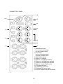
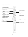
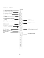
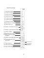
External powering of the mixer is via a 4-pin XLR (13).
XLR
Pin 1
Pin 2
0V
Charge
Pin 3
Pin 4
15V - 24V DC
12V - 15V DC
A suitable external power supply is Audio Developments’ AD100-09, but any external
DC source must be capable of delivering 750mA at 12V.
Note - When the chassis size exceeds 12 inputs, or when specified by the customer,
a
5 pin XLR (13) is fitted to accept external powering. The internal DC-DC Converter is
omitted. A suitable external power supply is Audio Developments AD 100-10.
XLR
Pin 1
Pin 2
Pin 3
0V
+ 12V DC
+ 12V DC
Pin 4
Pin 5
+ 48V DC
NC
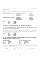
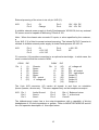
‘D’ connector (14) provides connection to an optional meter bridge - in which case, the
mixer’s meters should be routed to MON.
CONV
Pin
1
2
3
4
5
6
7
IDC
(1)
(3)
(5)
(7)
(9)
(11)
(13)
CONV
Chassis
Spare
Spare
Spare
Spare
PFL control
-V voltage rail
Pin
8
9
10
11
12
13
14
15
IDC
(15)
(2)
(4)
(6)
(8)
(10)
(12)
(14)
+V voltage rail
0V
PFL - left output
PFL - right output
Output D
Output C
Output B
Output A
The 6-pin XLR connector (15) carries all signals to and from an outstation
(boom operator, director etc). The return appears only on the headphones output.
XLR
Pin 1
Pin 2
Pin 3
Audio Ground
Send +
Send -
Pin 4
Pin 5
Pin 6
Ret + ] Balanced return
Ret - ] at line-level
Control
The talkback-send output has a low output-impedance with a capability of driving
headphones of 25 ohms impedance or greater. Refer to MONITOR MODULE section
for a full operation description of this output/return.
15