1
Neurophore BH-2
Micro-Iontophoresis
System User's Manual
BH-2 Mainframe Chassis
MS-2B Power Supply
BM-2 Balance Module
IP-2 Iontophoresis Pump Module
PPM-2 Pneumatic Pump Module
MA1 65-0200, MA1 65-0600
MA1 65-0201, MA1 65-0601
MA1 65-0202, MA1 65-0602
MA1 65-0203, MA1 65-0603
MA1 65-0204, MA1 65-0604
Publication 5403-003-REV-B
WEEE/RoHS Compliance Statement
EU Directives WEEE and RoHS
To Our Valued Customers:
We are committed to being a good corporate citizen. As part of that commitment,
we strive to maintain an environmentally conscious manufacturing operation. The
European Union (EU) has enacted two Directives, the first on product recycling
(Waste Electrical and Electronic Equipment, WEEE) and the second limiting the use
of certain substances (Restriction on the use of Hazardous Substances, RoHS).
Over time, these Directives will be implemented in the national laws of each EU
Member State.
Once the final national regulations have been put into place, recycling will be offered
for our products which are within the scope of the WEEE Directive. Products falling
under the scope of the WEEE Directive available for sale after August 13, 2005 will
be identified with a “wheelie bin” symbol.
Two Categories of products covered by the WEEE Directive are currently exempt
from the RoHS Directive – Category 8, medical devices (with the exception of
implanted or infected products) and Category 9, monitoring and control instruments.
Most of our products fall into either Category 8 or 9 and are currently exempt from
the RoHS Directive. We will continue to monitor the application of the RoHS
Directive to its products and will comply with any changes as they apply.
• Do Not Dispose Product with Municipal Waste
• Special Collection/Disposal Required
Table of Contents
Harvard Apparatus Medical Systems BH-2 Micro-Iontophoresis System User's Manual
1
SUBJECT
PAGE NO.
Warranty and Repair Information:
Manual Description ............................................2
Warranty ............................................................2
Repair Facilities and Parts ................................2
Serial Numbers ..................................................2
Introduction:
Features ............................................................3
Cautions..................................................................3
Specifications ....................................................4-5
System Description:
BH-2 Mainframe and Balance Module ..............6
MS-2 Power Supply ..........................................6
IP-2 Pump Module..............................................7-8
PPM-2 Pneumatic Pump Module ........................9
Recommended Setup Procedure:
Electrode Resistance Measurement ................10
Setting of Retention Current ............................11
Setting of Ejection Current ..............................11
Setup of Automatic Balance ............................11
Setup of Pneumatic Pressure Module ............12
PPM-2 Gas Input Connections:
Advantages of Micro Pressure Ejection ..........13
Pressure Ejection Into Saline......................13-14
Seven Barrel Micropipette ..................................15
Alignment Procedure:
BH-2 Balance Module ......................................16
IP-2 Module Alignment and Control Settings ..17
Bal. Module Alignment and Control Settings ..17
Final Adjustment and Control Settings ............18
Addendum to Neurophore BH-2 Manual ..........19
Warranty and Repair Information
2
Harvard Apparatus Medical Systems BH-2 Micro-Iontophoresis System User's Manual
Serial Numbers
All inquires concerning our product should refer to the serial number of the unit.
Serial numbers are located on the rear of the chassis.
Calibrations
All electrical apparatus is calibrated at rated voltage and frequency.
W a rr a n t y
Harvard Apparatus warranties this instrument for a period of one year from date of
purchase.At its option, Harvard Apparatus will repair or replace the unit if it is found
to be defective as to workmanship or material.
This warranty does not extend to damage resulting from misuse, neglect or abuse, normal wear and tear, or accident.
This warranty extends only to the original customer purchaser.
IN NO EVENT SHALL HARVARD APPARATUS BE LIABLE FOR INCIDENTAL OR
CONSEQUENTIAL DAMAGES. Some states do not allow exclusion or limitation of
incidental or consequential damages so the above limitation or exclusion may not
apply to you. THERE ARE NO IMPLIED WARRANTIES OF MERCHANTABILITY,
OR FITNESS FOR A PARTICULAR USE, OR OF ANY OTHER NATURE. Some states
do not allow this limitation on an implied warranty, so the above limitation may not
apply to you.
If a defect arises within the one-year warranty period, promptly contact Harvard
Apparatus, Inc. 84 October Hill Road, Building 7, Holliston, Massachusetts
01746-1371 using our toll free number 1-800-272-2775. Goods will not be accepted
for return unless an RMA (returned materials authorization) number has been issued
by our customer service department. The customer is responsible for shipping
charges. Please allow a reasonable period of time for completion of repairs, replacement and return. If the unit is replaced, the replacement unit is covered only for the
remainder of the original warranty period dating from the purchase of the original
device.
This warranty gives you specific rights, and you may also have other rights which vary
from state to state.
R e p a i r F a c i l i t i e s a n d P a rt s
Harvard Apparatus stocks replacement and repair parts. When ordering, please
describe parts as completely as possible, preferably using our part numbers. If practical, enclose a sample or drawing.We offer a complete reconditioning service.
CAUTION
This temperature controller is not registered with the FDA and is not for clinical use
on human patients.
CAUTION: Not for clinical use on human patients.
Publication 5403-003-REV-B
Introduction
Harvard Apparatus Medical Systems BH-2 Micro-Iontophoresis System User's Manual
3
Micro-Iontophoresis of ionized drugs from multi-barreled electrodes has evolved into
a practical method of testing electrophysiological action of putative neurohormones.
The NeuroPhore BH-2 System has been designed to facilitate the most stringent
requirements and provides precise stimulation and quantitative control for ejection of
drugs, in pharmaceutical studies of drug evoked neurosynaptic discharges.The BH-2
System has been developed with the guidance of active researchers with extensive
experience in Ionto-Phoresis techniques. Emphasis has been given in the design of
this system to reliability, performance, compliance to accommodate high impedance
multi-barreled micro-pipettes and to simplicity of operation.The NeuroPhore BH-2 is
modular and the system is comprised of the following assemblies:
*
*
BH-2 Mainframe & BM-2 Balance
Module
*
PPM-2 Pneumatic Pump Module
*
MS-2 Power Supply
IP-2 Pump Module
*
MS-7PB/MS-7MT Seven Barrel
Pipettes
F e a t u re s
*
Modular Design
*
Will accommodate 7 barrel
pipette
*
All Solid State
*
+105V compliance (no batteries)
*
Automatic Current Neutralization
*
Digitally controlled eject and
pause timing
*
Injection and retention currents and
electrode resistance readout with
digital display
*
Unbalance and out of compliance
auto-indicators
*
External analog input control over
injection current
Cautions
•
Do not remove any modules while the power in ON.
•
When a module is removed ascertain that same is placed in a non-electrostatic or
grounded environment since electrostatic charges may damage some of the integrated circuits.
•
Allow minimum equipment warm up time of 15 minutes prior to use.
•
When measuring electrode resistance it is recommended that the electrode
resistance values be measured “one module” at a time. In other words select the
positive or negative position on the Current Resistance Selector Switch (2a - page
9) and after the resistance measurement has been completed, return the switch
to the center nA position.
•
It is recommended that the resistance measurement be made with the auto balance switch (3b - page 18) on the BM-2 balance module, set in the UNBAL current position. It is noteworthy that when the instrument is set up for automatic
current balance (switch set in UNBAL CURR position on Auto Bal/Current
Selector (3b - page 6) the current used for electrode resistance Measurement 50
nA is automatically balanced and as such prevents any ground going currents at
the cell junction. It is therefore required that the current be measured one at a
time to prevent any feedback between resistance current channels.
•
In order to operate this system it is required that the OUTPUT (13b - page 6) be
terminated into an external load. This applies specifically to the balance channel
since no internal (dummy load) is provided. In other words, the Micropipette
balance barrel when connected provides such a termination.
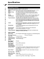
Specifications
Harvard Apparatus Medical Systems BH-2 Micro-Iontophoresis System User's Manual
4
Specifications
MSC-2 Power Supply
Outputs
±125 V @ 0.1 Amps, ±15 V @ 0.5 Amps, ±5 V @ 3 Amps, line
operated 115-220 VAC, 50-60 Hz
IP-2 Module
Current Pump
Ejection Current
Compliance ±105 V, linear constant current source
Pulsing controlled by ejection timing module switch; amplitude
adjustable by 10-turn ejection control and range switch from 0-50
or 0-500 nA; polarity selected by polarity switch; accuracy=±1 nA
Ejection Indicator Red LED lamp indicates eject time period; green LED lamp indicates pause time period
Retention Current Amplitude adjustable by front panel dial from 0-50 nA; polarity is
automatically set opposite to ejection current polarity
Analog Input
Lemo miniature receptacle ground referenced 5mV/nA; input
impedance 100 kΩ
Analog Output
Lemo miniature receptacle ground referenced 5mV/nA
Sync Output
Lemo miniature receptacle, TTL pulse time incident with eject
pulse
CURRENT AND RESISTANCE
Metering System Digital meter display 3 digits and sign
RESISTANCE/CURRENT SWITCH
Current Mode
Switch in center “nA” position; digital display reads total current in
nA passed through the microelectrode pipette (sum of retention
and ejection current)
Resistance Mode Switch in either (pos.) or (neg.) megaohms position; digital display
reads actual electrode barrel resistance in megaohms derived by
passing positive or negative constant current (50nA) through electrode pipette
No Compliance
Digital display flashes whenever electrode barrel resistance
Indicator
exceeds working range of current pump (i.e., when electrode
resistance times current exceeds compliance of ±105V)
Voltage Readout Depressing switch causes digital display to read voltage across
Switch
pipette
BM-2 Balance Module
Neutralization (Bal.)Max. ±2500 nA automatically controlled
Pump Range
Compliance ±105 V linear constant current source, manually
Current Pump
adjust. 0 to 500 nA by pump control; polarity selected + /OFF/ switch
Dig. Meter Display 3 digits and sign
Publication 5403-003-REV-B
Specifications
Harvard Apparatus Medical Systems BH-2 Micro-Iontophoresis System User's Manual
5
Specifications (Cont’d)
UNBALANCE CURRENT/CURRENT PUMP SWITCH
Unbalance Current Digital display reads unbalance (ground going) current in nA; in
Mode
this mode, automatic current neutralization provided
Current Pump
Auto. balance feature is switched off; display reads amount
Mode
of current in nanoamperes passed through balance barrel as
adjusted by Pump control
Single
In single cycle mode start switch or external trigger initiates each
Cycle/Recycle
cycle; in recycle mode, once start switch or external trigger is
actuated, repetitive cycles commence automatically
Time Unit Switch Two basic time units selectable, 10 msec or 1 sec; in 10 msec
position, eject and pause time switches of IP-2 modules can be
set to cover time range from 0 to 990 msec with 10 msec resolution; in I sec position, time scale expanded from 0 to 99 sec with
one sec resolution
Inputs
Cycle start, stop, trigger/gate # 1 through # 5; banana jacks terminals, floating input, optically coupled; input voltage ±5 to ±15 V
TTL compatible
Analog Input
Lemo miniature receptacle, ground referenced 5mV/nA; input
impedance 100 Ω
Analog Output
Lemo miniature receptacle, 5mV/nA ground referenced
Sync Output
Lemo miniature receptacle, TTL pulse
Output Connector Seven pin miniature connector, mates with ultra flexible cable
leading to microelectrode holder
PPM-2 Module
Source Gas
Air or nitrogen recommended (no explosive or combustible gases)
Max. Input Pressure
125 psig (7.8 kg/cm2)
Input Filter
5 micron element
Output Pressure 0 to 99.9 psig (0 to 7 kg/cm2)
Output Pressure Three decimal digits
Display
30 msec
Min. Pressure
Pulse Width
Max. Pressure
99 sec (990 sec optional)
Pulse Width
Quick connect type
Gas Input and
Output Couplings
Analog Output
Lemo miniature connector voltage proportional to output pressure;
0 to -999 mV full scale in psig setting 0 to 700 mV full scale in
kg/cm2 setting
Sync. Output
Lemo miniature connector TTL pulse, time incident with output
pressure pulse
Eject Time Indic. Red LED
Pause Time Indic. Green LED
Dimensions
47 x 21 x 35 cm (19 x 8.75 x 14 in), W x H x D
Weight
System: 8.2 kg (18 lbs); Power Supply: 11 kg (24 lbs)
System Description
6
Harvard Apparatus Medical Systems BH-2 Micro-Iontophoresis System User's Manual
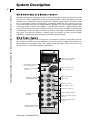
BH-2 Mainframe and Balance Module
The BH-2 mainframe is designed to be 19 inch rack mounted and is prewired to accept
one balance and a combination of five IP-2 pump modules and/or pneumatic pressure
modules (any combination of five plus balance module). The balance module in addition to providing current neutralization (automatic feedback and control of inverse
sum of all pump currents) has independent capability of current pump settings with
a working range of 0-500 nanoamperes. The module includes a digital display, time
clock, provisions for electrical and manual Cycle, Start/Stop and Single Cycle Recycle
switch,Trigger and Gate input terminals to initiate externally controlled Eject pumping action of respective modules. Analog input for balance or drive with override
capability. Analog output for monitoring of unbalanced currents.
MS-2 Power Supply
The AC power supply is self contained in a rack-mount cabinet and provides all voltages required to operate the NeuroPhore System. The power supply interconnects to
the mainframe via flexible cable. The supply works off either 115 or 220 VAC, 50 or
60 Hz source (a selectable jumper is provided).
1b-Balance current digital
display (3 digit & sign)
3b-Automatic balance and
current pump selector
4b-Pump current polarity
selector
6b-Trigger input Start
and Stop Terminals
2b-Pump current control
0-500 nA (10 turn Pot.)
5b-Manual Start and
Stop Control
8b-Single cycle and
recycle selector switch
9b-Time Clock Selector
7b-Trigger Gate Input
Terminals
10b-Sync Output Terminal
12b-Analog output terminal
5 mV/nA
11b-Analog input terminal
5 mV/nA
13b-Micropipette Current
Drive Output Connector
Publication 5403-003-REV-B
IP-2 Pump Module
Harvard Apparatus Medical Systems BH-2 Micro-Iontophoresis System User's Manual
7
The system housing (mainframe) can accommodate up to five IP-2 pump modules and
as such will accommodate a seven barrel pipette to handle five drug, one balance and
one recording barrel. Each IP-2 pump module includes control for precise settings of
current magnitude and polarity (retention 0 to 50 nanoamperes, ejection 0 to 500
nanoamperes). The actual current and polarity is continuously displayed digitally and
can be externally monitored at the analog output terminal.
Note: The system can also accommodate up to 5, any combination of pneumatic and iontophoretic modules and thus provide full control of simultaneous pneumatic and iontophoretic ejection of drugs.
E j e c t i o n Ti m i n g a n d M o d e S w i t c h
The mode switch provides five push button controls which include operations such
as Cycle,Trigger, Gate, Continuous and Termination.
Cycle Mode
In the cycle mode, by virtue of selecting single or recycle operation on the BH-2 module, an incoming trigger or cycle start push button will initiate the ejection pumping
action. In this mode each succeeding pump module is automatically triggered after
the pause time of the preceding event has been completed. Both EJECT and PAUSE
times can be preset to cover a range from 10 to 990 milliseconds with a 10 millisecond resolution and 1 to 99 seconds with a 1 second resolution.
Tr i g g e r Mo d e
When the TRIG. switch is energized the eject time interval will be started by virtue of
the respective incoming trigger pulse applied to the input panel of the BH-2 balance
module. Eject timing interval can be preset covering a range form 10 to 990 milliseconds with a 10 millisecond resolution and 1 to 99 seconds with a 1 second resolution.
Gate Mode
When the Gate switch is energized the eject current will be started by virtue of a gate
input signal provided to the respective TRIG/GATE terminals on the BH-2 balance
module. The Eject-Pause time settings are automatically disengaged in this mode, since
the Eject time is slaved to the duration of the gate input.
Continuous Mode
When the CONT. switch is energized the ejection pump current is continuously maintained.
Te rm i n a t i o n M o d e
When the TERM. switch is energized the output is automatically diverted from the
micropipette preparation into an internal “dummy load”(100 megohms). This function
is particularly useful for testing of possible instability in the preparation pipette.
Analog Input
The analog input terminal is available to facilitate externally controlled current pumping action. An external voltage applied to the input will generate a pumping current
at a ratio of 5 millivolt/nanoampere. This current will be summated with any preset
pump current governed by both the Retention and Eject controls. The combined magnitude and sign of the summated pumping current is displayed on the digital display
of each corresponding pump module. This input can be connected to a computer D/A
converter when external programming is desired.
IP-2 Pump Module
8
Harvard Apparatus Medical Systems BH-2 Micro-Iontophoresis System User's Manual
Analog Output
The analog output terminal provides a buffered voltage which is proportional in magnitude and polarity to the actual current passed from the current pump into the
pipette. The conversation ratio is 5 mV/nA. This output can be polygraphically recorded to monitor progress of the experiment.
S y n c O u t p u t Te r m i n a l
The sync output provides a TTL pulse that coincides with the eject time. This output
is provided to trigger external devices such as computer, event counter, etc.
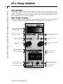
1a-Pump Current/Electrode
Resistance Digital Display
(3 digits and sign)
2a-Pump Current/Electrode
Resistance selector
5a-Ejection Current Selector
0-50 nA to 0-500 nA
4a-Retention Ejection
Current Polarity Switch
7a-Eject and Pause Time
Indicator
6a-Ejection Current Control
(10 turn Pot.)
3a-Retention Control
(0-50 nA)
9a-Eject Mode Switch
(Cycle/Trigger/Gate/
Continuous Termination)
8a-Eject & Pause time
digital preset switch
10a-Sync Output (Incident
with Eject Time Interval)
11a-Analog Input 5 mV/nA
(Ext. Signal Drive Input)
13a- Pipette Voltage
Display Switch
12a-Analog Output 5 mV/nA
IP-2 Pump Module Controls
Publication 5403-003-REV-B
PPM-2 Pneumatic Pump Module
Harvard Apparatus Medical Systems BH-2 Micro-Iontophoresis System User's Manual
9
The pneumatic pump module has been designed specifically for pressure injection of
drugs in pharmacological studies of drug evoked synaptic discharges. Emphasis has
been given in the design as to pressure control and regulation (0 to 30 psi) or (0 to 2.2
kg/cm2) as well as precise timing capability.
The Pneumatic Pressure Module PPM-2 is compatible with the BH-2 (NeuroPhore)
microiontophoresis main frame. By virtue of interchanging the iontophoresis pump
module (IP-2) with a pneumatic pressure pump (PPM-2) the overall system capability
can be expanded for simultaneous pressure and iontophoretic injection of drugs from
a multibarrel pipette.
The PPM-2 is comprised of a precise pressure regulator, digital display, transducer and
a timing mode switch. It connects to an external pressure source (such as a compressed bottle of N2) can be set to provide continuous or periodic pressure pulses
ranging (0 to 30 psi) with 0 to 0.5V) proportional to the output pressure as well as a
sync pulse coincident with the pressure start cycle.
E j e c t i o n Ti m i n g a n d M o d e S w i t c h
The mode switch provides five push button controls which include operations such as
Cycle,Trigger, Gate, continuous and termination.
Cycle Mode
In the cycle mode after selecting single or recycle operation, the start push button will
initiate the ejection pumping action. In this mode each succeeding pump module is
automatically triggered after the pause time of the preceding event has been completed. Both eject and pulse times can be present to cover a range from 1 to 99 seconds
with a 1 second resolution.
Tr i g g e r Mo d e
When the Trig. switch is energized the eject time interval will be started by virtue of
an externally applied trigger pulse fed to the respective inputs on the control panel.
Eject timing interval can be preset covering a range of 1 to 99 seconds with a 1 second resolution.
Gate Mode
When the Gate switch is energized pumping action will be started by virtue of a gate
input signal applied to the respective trigger/gate terminals on the control panel. The
eject and pause time settings are not operative in this mode, since the eject time function is slaved to the duration of the gate input.
Continuous Mode
When the Cont. switch is energized the eject pump pressure is continuously maintained.
Te rm i n a t i o n M o d e
When the Term. switch is energized the output pressure is automatically diverted from
the preparation into an internal “Dummy Load”. This function is particularly useful for
setting up the desired pressure range and timing while preventing ejection of any drug
from the pipette.
Recommended Setup Procedure
Harvard Apparatus Medical Systems BH-2 Micro-Iontophoresis System User's Manual
10
Prior to turning power “ON” set (push in) the TERM-100 M Switch (9A, p. 8) on each
of the pump modules, thus terminating each pump into the internal 100 M Load.
a) Turn all Retention controls (3A, p. 8) and Eject controls (6A, p. 8) to zero
(fully counter clockwise).
b) Connect the reparation to current drive output cable connector (13B, p. 6).
Balance Module Front Panel Connector
Board
Ground
Black
Pin 7
IP-1 Pump Module
Brown
1
IP-2 Pump Module
Red
2
IP-3 Pump Module
Orange 3
IP-4 Pump Module
Yellow
4
IP-5 Pump Module
Green
5
Balance Module
Blue
6
J11 - Balance Module P.C.
A
G
F
E
D
C
B
c) Turn power switch ON.
d) Mount the filled pipette into the micromanipulator assembly.
e) Connect the electrical and/or pneumatic connections to the pipette.
f) Advance the pipette into the outer layer of tissue (mainly to establish contact
between pipette tip and tissue fluid).
g) Release the TERM switch (by releasing the TERM switch the pipette is electrically/pneumatically coupled to the apparatus).
E l e c t ro d e R e s i s t a n c e M e a s u r e m e n t
Electrode resistance measurement is achieved by setting the switch (Pump current
and electrode resistance selector (2A, p. 8) into positive or negative MΩ setting.
Ascertain that TERM-100 MΩ (internal dummy load resistor) mode switch (9A, p. 8) is
released.
Measure the electrode resistance by immersing the tip of the micropipette at the initial stage of entry into the tissue (or a droplet of saline) to establish the resistance value
of each barrel with ground reference. Ascertain appropriate resistance polarity (electrode resistance selector,2A,p.8) that coincides with ejection current polarity for each
drug contained in the barrel.
Resistance value for each barrel should be measured one at a time. The selection of
the appropriate polarity of the resistºance selector switch (positive or negative) to correspond to the cathodic or anodic ion composition of the drug is vital. Inasmuch as
during the resistance measurement the resistance metered circuit will generate a continuous 50 nanoamperes of current, it is advisable that the polarity of this current be
such to eject the drug ions, thus avoiding the possibility of tissue or other particles
from the surrounding fluid to clog the barrel. It is also suggested that the front handle bar handles on each module be used for marking information such as type of drug,
barrel resistance, retention and ejection values, etc. since such information can be very
useful during control of the experiment.
After the resistance value of each pipette has been determined it is recommended that
the resistance toggle switch be returned to center or inactive position. The above procedure should be repeated for each active barrel.
Publication 5403-003-REV-B
Recommended Setup Procedure
11
Harvard Apparatus Medical Systems BH-2 Micro-Iontophoresis System User's Manual
S e t t i n g o f R e t e n t i o n C u rr e n t
a) Press either Cycle,Trigger of Gate button on the Eject Mode switch (9A, p. 8).
b) Set the retention polarity switch (4A, p. 8) to coincide with the retention
required of each drug and set the retention current control (3A, p. 8) for the
desired current magnitude. The retention current and polarity can be read on
the digital display.
S e t t i n g o f E j e c t i o n C u rr e n t
a) Set the EJECT Mode switch (9A, p. 8) to CONT. mode and adjust the control
(6A, p. 8) to the desired current magnitude.
b) Set the EJECT Mode switch (9A, p. 8) to CYCLE or any other mode if external
timing is required.
c) Select the appropriate Eject and Pause time intervals on each of the thumb
wheel switches (8A, p. 8).
d) Select the appropriate Time Unit by setting switch on the BM-2 Balance
Module (9B, p. 8). (1 sec. or 10 ms.).
e) Select Single or Recycle Mode Switch (8B, p. 6) for desired timing.
f) Press Cycle Stop switch (5B, p. 6) to release latch and then depress Cycle
Start Switch to initiate cycle run.
Setup of Automatic Balance
Set Automatic Balance and Current Pump selector switch (3B, p. 6) to the unbalance
current position.The 3 digit display will indicate a reading close to zero + 0.001 or 2
nanoamperes. For fine control adjustment it is recommended that the pump current
and polarity selector to be switched to either positive or negative position (opposite
to the polarity indicated on the digital display).
Adjust the pump current control (2B, p. 6) to as close to zero as possible. NOTE: The
slight variations may be noted such as a jump of one digit. This variation is attributed
to the inherent noise of A/D converter.
Recommended Setup Procedure
12
Harvard Apparatus Medical Systems BH-2 Micro-Iontophoresis System User's Manual
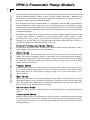
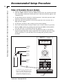
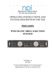
S e t u p o f P n e u m a t i c P re s s u r e M o d u l e
1. Connect the gas input pressure as shown below.
2. Push the TERM switch in (with the TERM switch in the “IN” position the module is internally terminated and the pressure is diverted from the pipette into
a dummy load).
3. Set the Mode Selector Switch to CONT. operation. Select the pressure units
switch to either psig or Kg/cm2 position.
4. Adjust the pressure regulator to the desired pressure level and note the 3
digit pressure display.
5. Set the Eject and Pause time settings for the desired timing.
6. Select the desired mode setting to either cycle or other mode of operation.
7. Release TERM switch (by pushing and releasing the TERM switch pushbutton).The pressure is now directed into the pipette.
8. To monitor analog output connect the polygraph recorder to the Analog
Output terminal thus the analog of pressure (0 to 1000 mV full scale in the
100 psi. position) or (700 mV full scale in the Kg/cm2 position) will be
recorded.
PNEUMATIC
PUMP
psig
container
pressure
gauge
PPM-2
kg/cm2
PRESSURE
ON
pressure
regulator
output
pressure
gauge
PRESSURE REGULATOR
CYCLE TRIGG GATE CONT TERM
1/8" Diam.
flexible
tubing
EJECT TIME
1
1
PAUSE
2
2
OUT
Use nitrogen or air as a pressure source.
Do not use combustible media such as
oxygen or propane. Alternate pressuresource can ve an air compressor with a
storage tank. Input pressure source
should not exceed 50 psi (3.2 kg/ cm2).
GAS IN
ANALOG SYNC.
To pipette
Publication 5403-003-REV-B
PIPETTE
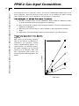
PPM-2 Gas Input Connections
Use nitrogen or air as a pressure source. Do not use combustible media such as oxygen or propane. Alternate pressure source can be an air compressor with a storage
tank. Input pressure source should not exceed 50 psi (3.2 kg/cm2).
A d v a n t a g e s o f M i c ro - P r e s s u re E j e c t i o n
a) Pressure ejection can be used to administer drugs which are difficult to deliver with conventional microiontophoretic techniques.
b) Does not share the leakage and warm-up problems associated with microiontophoretic techniques.
c) Micropressure ejection may be more amiable to dose dependent relationships.
d) Offer linear and reproducible delivery characteristics. (See illustrations.)
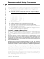
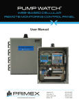
P re s s u re E j e c t i o n i n t o S a l i n e
Figure 1
The effect of increasing ejection
time on the release of 3H-sucrose.
3H-Sucrose was pressure ejected
from a multibarreled pipette at 5
(open circles), 10 (closed squares),
20 (open triangles) or 30 (closed
circles) psi of nitrogen. The ordinate represents total counts per
minute tritium collected minus the
blank.
Pressure Ejection into Saline
30 PSI
4
3
20 PSI
3
10 CPM-BK
Harvard Apparatus Medical Systems BH-2 Micro-Iontophoresis System User's Manual
13
2
10 PSI
1
5 PSI
10
20
TIME {SEC}
30
PPM-2 Gas Input Connections
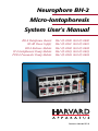
Figure 2
The effect of increasing ejection
pressure on the release of 3Hsucrose. 3H-sucrose was pressure
ejected from a multibarreled
pipette in 1-(open circles), 2(closed squares), 10-(open triangles) or 30-(closed circles) second
pulses. The ordinate represents
total counts per minute tritium collected minus the blank.
30 SEC
4
3
103 CPM-BK
Harvard Apparatus Medical Systems BH-2 Micro-Iontophoresis System User's Manual
14
10 SEC
2
Figure 3
Dose dependent inhibition of cortical neuronal discharge induced by
micropressure ejection of 2dA in
1
the absence of regularly repeated
2 SEC
pulses of drug. (A, B, and C)
1 SEC
Ratemeter records from a single
cerebral cortical neuron showing
the magnitude of inhibitions elicit5
10
20
30
ed by applying various pressures to
PRESSURE {PSI}
the 2dA-filled barrel. Duration of
ejection is shown by the underlying bar. Percent inhibition is indicated above each 2dA response. (D) Dose-dependent inhibitions produced in one cell. The 2dA is applied with large variations in interejection time over a 60-minute period.
Figure 4
Ratemeter records from two neurons demonstrating typical controls for the physiological effects of micropressure ejected drugs. 2dA caused marked inhibitions of
Purkinje cell firing rate when applied at 20 psi for 2 seconds.
Figure 5
Reproducibility of the micropressure ejection technique. (A) An average of 1057 +
24 counts per minute of tritium was collected from five separate pressure ejections of
3H- sucrose from one pipette, each applied at 20 psi for five seconds. Vertical line represents one standard error of the mean. (B and C) Ratemeter records from two cerebellar Purkinje cells which illustrate the reproducible physiological responses to
repeated micropressure ejections of drugs at two-second pulses of 1 psi (underlying
bars). NE (B) or GABA (C), when repeatedly applied, produced uniform inhibitions of
neuronal activity which did not vary for periods of time of up to 1.5 hours.
Figure 6
Typical results illustrating spontaneous Purkinje cell discharges (recorded with MSC
multibarrel pipette).
Publication 5403-003-REV-B
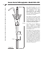
Seven Barrel Micropipette: Model MS-7PB
Harvard Apparatus Medical Systems BH-2 Micro-Iontophoresis System User's Manual
15
The MS-7PB pipette has been
designed for iontophoretic use as
well as pneumatic ejection of drugs
and compliments the BH-2
NeuroPhore System. The standard
blank consists of seven barrels,
pyrex Omegadot tubing, 1.5 mm
O.D. and 1.2 mm I.D, prepulled to 2
mm formation as shown.
The design of the pipette readily
lends itself for electrical connection
by inserting Ag wire or tube attachment for pneumatic use. The overall
length of the blank assembly is 10
centimeters and fits the Narishige or
an equivalent electrode puller.
MS 7 P
5 61 2 3
10 cm
22 mm
2 mm
Scale 2:1
The pipette can be supplied in
either configuration, prepulled
blanks as shown or in a pulled
micron tip format. The micron tip is
not bumped and therefore can be
finalized prior to use.
The orifice ratio of each barrel is
0.80 and thus is optimized for minimal tip resistance when pulled to
micron size. Omegadot tubing permits easy filling. Fanned-out outer
barrel assembly provides separation
thus avoiding leakage due to spills
between barrels. The 22 millimeter
long twisted segment of the blank
assembly assures singular tip formation during pulling action and provides flexibility in selection of a
desired tip configuration.
Alignment Procedure
Harvard Apparatus Medical Systems BH-2 Micro-Iontophoresis System User's Manual
16
BH-2 Balance Module
The BH-2 System is designed to provide an
“Automatic Balancing” feature in order to null out
any voltage that may appear due to retention and/or
ejection at the cell junction.
"10 VR"
VR105
VR109
VR102
VR108
VR101
"A" {RIGHT}
R105
U27
VR107
U25
VR110
Needless to say when a system is dispatched the
automatic balancing controls is precisely adjusted
at the factory and as such will track pump current
(500 nA) retention and/or ejection accurately and
balance well within + 1 nA at full scale. However,
in the field, situations may arise whereby an IP-2
BH-2 Balance Module
pump module is added and realignment of the
balancing may become necessary. To accommodate this eventuality the realignment
procedure as outlined here and should be followed.
U21
U26
U22
VR103
VR105
VR104
R109
"B" {LEFT}
Publication 5403-003-REV-B
U23
U30
Alignment Procedure
17
Harvard Apparatus Medical Systems BH-2 Micro-Iontophoresis System User's Manual
I P - 2 M o d u l e A l i g n m e n t a n d C o n t ro l S e t t i n g s
Test Conditions
1. Only one IP-2 module powered at one time.
2. Retention: Fully CCW (counterclockwise).
3. Ejection: Fully CCW.
4. Current/Resistance switch in “nA” position.
5. “Gate” push button in.
6. “Term” push button in.
"A" {RIGHT}
R165
VR106
U119
VR101
VR102
VR103
U102
U118
VR104
U101
VR106
R175
"B" LEFT
IP-2 Module Adjustment
IP-2 Module
a) Set R133 (lower pin) to 0V (zero voltage)
(pin 6, U102) by adjusting VR103.
b) Ground point “B” (R172 left pin), set point “A” (R165 right pin) to 0V (zero
voltage) by adjusting VR106.
c) Ground point “A” (R165 right pin), set point “B” (R172 left pin) to 0V zero
voltage by adjusting VR105.
d) Repeat b. and c. two or three times for better adjustment.
e) Adjust VR104 to obtain + 000 reading on digital display.
B a l a n c e M o d u l e A l i g n m e n t & C o n t ro l S e t t i n g
Test Conditions
1) Balance module alone (No IP-2’s)
2) Output connector terminated by 10
Mohms resistor.
3) Unbal. current/current pump switch
in “unbal” position.
4) Polarity switch in center “OFF” position.
5) “Time Unit” switch in 10 ms position.
TO: OUTPUT
CONNECTOR
PIN NO. 1
2
(IP-2's) 3
4
7x50M
{
5
(BAL.) 6
TO OSCILLOSCOP
(H. GND) 7
RT
Adjusting Procedure
External Load for
a) Set R104 (lower pin) for 0V (zero
Testing
and Adjustment
voltage) by adjusting VR 103.
b) Ground point “B” (R109 left pin), set
point “A” (R105 right pin), to 0V (zero voltage) by adjusting VR 101.
c) Ground point “A” (R105 right pin), set point “B” (R109 left pin), to 0V (zero
voltage) by adjusting VR 102.
d) Repeat b. and c. two or three times for better adjustment.
e) Set 0V (on display) by turning VR 104.
f) Obtain + 000 reading by adjusting VR 105.
g) Set VR 107 to obtain 2.000V+ 1mv at pin 2, U-27.
h) Using voltmeter, set terminal (location: CR114 hole @ 7 o’clock) to 4.500V +
0.1V by adjusting VR 106.
i) Set VR 110 (unlabeled) to obtain 1 ms pulse train at pin 1, U-30.
Alignment Procedure
18
Harvard Apparatus Medical Systems BH-2 Micro-Iontophoresis System User's Manual
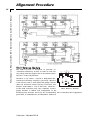
F i n a l A d j u s t m e n t a n d C o n t ro l S e t t i n g
Test Conditions
1. All IP-2 modules in “CONT” mode.
2. “Retention” and “Ejection” fully CCW.
3. “TERM” push button out.
4. All IP-2’s and BAL module output connected to common point through 50
Mohm resistor. This point tied to ground through an RT = 50 Mohm resistor.
5. Oscilloscope connected across RT. (Making effective RT/Scope approximately equal to 1 Mohm).
6. Oscilloscope setting: Horizontal 5 ms/division, line sync.Vertical: 5mV/division.
Adjusting Procedure (BM-2 Balance Module)
a. Adjust VR 103 to obtain 0V (zero voltage) on CRO.
b. Adjust VR 104 and/or VR 105 to obtain + 000 Bal display.
c. Set unbalance curr/current pump switch to current pump position. Set VR
108 to obtain 0V on CRO.
d. Set VR109 to get + 001 reading on balance display. Return unbalance current/current pump switch to unbalance current position.
Adjusting Procedure (IP-2 Module)
a. Select one IP-2 module and turn Ejection control fully clockwise. Correct DC
offset as measured by CRO by adjusting VR 101 until OV reading is reached.
Reverse ejection polarity and correct DC offset on CRO with VR 101 when
necessary. Return ejection control to zero (CCW).
b. Repeat step “e” for all IP-2 modules.
c. Press “Gate” button on all IP-2’s.
d. Turn ejection controls fully clockwise on all IP-2’s.
e. Set range switches to 500 nA on all IP-2’s.
f. Depress “CONT” button on one IP-2 and adjust VR102 to obtain + 001 reading
on balance display. Depress “GATE” button.
g. Repeat step “f” on all IP-2’s.
Publication 5403-003-REV-B
Addendum to Neurophore BH-2 Manual
19
Harvard Apparatus Medical Systems BH-2 Micro-Iontophoresis System User's Manual
R e f : P i p e t t e Vo l t a g e D i s p l a y
All IP-2 Modules manufactured after December 1981 are fitted with an additional push
button switch. This switch is marked “Push V”and it is mounted above the module handles between the ANALOG and the SYNC OUT connectors.
Depressing this switch will cause the digital display to read the voltage across the
pipette equal to the current flow through the pipette times the pipette impedance.
(i.e. by Ohms Law:V = R *I)
The voltage readout will function whenever the “Push V” button is depressed, regardless of the position of other controls. Therefore the pipette voltage can be measured
during the drug ejection, retention or impedance checks.
Specifications
Resolution
1/10 Volt
Maximum Range
+ 99.9 Volt