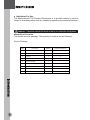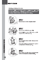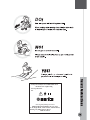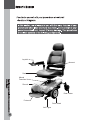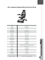
1
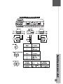
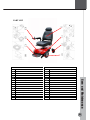
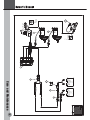
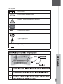
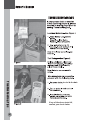
Power Chair P318
Indications For Use
Quantity of Contents
Device Description
2
2
3
4
6
10
12
14
15
16
17
18
19
Seat Removal
Shroud Removal
Attach Shroud
Remove Battery
21
Operating Your Powerbase Wheelcaair
Seat Height Adjustment
Armrest Width/Height Adjustment
Armrest Angle Adjustment
Footrest Angle Adjustment
Headrest Height Adjustment
Joystick Postion Adjustment
Manual Freewheel Levers
VR2 Controller Operation
Batteries and Charging
22
22
23
23
23
23
24
25
30
Care And Maintenance
Daily Checks
WEEKLY CHECKS
Monthly Checks YEARLY CHECKS
Wheel Replacement
Wiring Harnesses
Part Lists
Wiring Diagram
Iec Symbols
34
35
36
37
39
40
41
t
Troubleshooting Tips
42
44
adjusted
Indications For Use
The Merits Model P318 Powered Wheelchair is to provide mobility to persons
limited to a seated position that are capable of operating a powered wheelchair.
Cautions
Federal law restricts this device to sale by or on the order of a physician.
Quantity of Contents
The device is in one package: The quantity of contents are as following:
Device Package
Item
Component
Quantity
Note(Sold separately)
1
Power Base
1
2
Joystick
1
V
3
Charger
1
V
4
Power cord
1
V
5
Owner’s manual
1
6
Battery connecting wire
2
V
7
Tool kit
1
V
8
Seat
1
V
7
Armrest Ass’y. L/R
1L/1R
V
Device Description
Model P318 Powered Wheelchair is battery powered, front wheel motor
driven and is controlled by the PG power wheelchair VR-2 50amp controller.
The user interface is a joystick. P318 is powered by two 12 VDC 34ah (U1)
batteries. The batteries are charged by a 4A off-board charger connected
with 3-pin Microphone Connector to the charging socket on the joystick. The
approximate driving range on fully charged batteries is up to 28km (18mi).
The chair frame is a rived nut and welded steel construction and includes
two front drive wheels with drive units (including motor, gear, brake), batteries and rear pivoting casters. Depending on users needs, the joystick motor
control is mounted to the left or right armrest. When the user activates the
joystick, the controller receives a signal to release the brakes. With the
brakes released, the wheelchair is allowed to move in the direction the joystick is actuated. When the user releases the joystick, the chair slows to a
stop and the brakes are automatically re-engaged. The solenoid electromechanical brakes allow the user to stop by letting go of the joystick.
The upholstery of the device complies with EN 1021-1/-2:2006: Furniture:
Assessment of the ignitability of upholstered furniture: Ignition source:
Smouldering cigarette/ Match flame equivalent
The device can be operated on dry, level surfaces composed of concrete,
blacktop, or asphalt under normal driving conditions.
SAFETY WARNING
YOUR AUTHORIZED DEALER, PROVIDER, THERAPIST(S), AND/OR OTHER HEALTHCARE
PROFESSIONALS ARE RESPONSIBLE FOR DETERMINING YOUR REQUIREMENT FOR A
SEAT BELT FOR SAFE OPERATION OF YOUR MOBILITY DEVICE.
REQUIRING A SEAT BELT TO SAFELY OPERATE YOUR MOBILITY PRODUCT, MAKE SURE
IT IS FASTENED SECURELY IN ORDER TO REDUCE THE POSSIBILITY OF A FALL FROM
THE MOBILITY PRODUCT.
Warnings
DO NOT use an escalator to move a wheelchair between floors. Serious
bodily injury may occur.
DO NOT lean over the top of the back upholstery to reach objects from
behind as this may cause the wheelchair to tip over.
DO NOT shift your weight or sitting position toward the direction you are
reaching as the wheelchair may tip over backwards or sideways.
DO NOT tip or wheel the wheelchair without assistance, unless you are
highly skilled.
DO NOT attempt to stop a moving wheelchair with wheel locks. Wheel
locks are not brakes.
DO NOT stand on the frame of the wheelchair.
ALWAYS use caution when transferring in or out of the wheelchair. Every
precaution should be taken to reduce the transfer distance. Also be
certain the wheel locks are engaged to prevent the wheels from moving.
Cautions
Riding over curbs or obstacles can cause tipping and serious bodily harm.
If you have any doubt that you can safely cross any curb or obstacle,
ALWAYS ASK FOR HELP. Be aware of your riding skills and personal limitations. Develop new skills only with the help of a companion.
The wheelchair is not designed for weight training and is unsafe for use as
a seat while weight training. Weight training from the wheelchair substantially changes the stability of the chair and may cause tipping.
EMC
to do so.
Warning: The wheelchair might disturb the operation of devices in its
environment that emit electromagnetic fields (e.g. alarm systems of
shops, automatic doors)
DO
DO
6
6
DO
model Electrically Powered Wheelchair P318
maximum user weight 136Kg
Year of production:
SN:
Protect against splashing water:IPX4
MERITS HEALTH PRODUCTS CO., LTD.
No. 18, Jingke Road, T.P.M. T Park, Nantun District,
Taichung City 40852, Taiwan, R.O.C.
Made In Taiwan
Joystick
Armrest
Seat
Manual
Freewheel Lever
Shroud
Rear Caster
Footrest
Drive Wheel
Anti-Tipper
a
P322
P318
Length
84.7cm/33.4”
Width
60.6cm/23.9”
Seat Width
18”
Seat Height
51cm~56.1cm/
(from ground)
20.1”~22.1”
Seat Height
42cm~47.1cm/
(from deck)
16.5”~18.5”
Speed
6.4kph/4mph
Range up to
28km/18mi
Weight Capacity
136kg/300lbs
BaseWeight
28.5kg/62.7lb
Seat Weight
17.4kg/34.8lb
Battery Weight/ea
12kg/26lb
Motor
DC24V/130W
Brake
Intelligent regenerative electromagnetic brake
Controller
PG nVR2 50A
Battery
12V U1*2pcs
Charger
4A off-board
Gradient
6°(300lbs)
Caster Wheel
6” PU tire
Drive Wheel
9” PU tire
Recommended Storage and
Dry (15%~95% Non-Condensing), Well ventilated area -20°C ~
Shipping Temperature
60°C (-4°F ~ 140°F) Without batteries
a
Mode No.
Type B applied parts: seat, armrest, foot plate, joystick module.
Classification: Internal powered equipment by 24 VDC, Class II in charging mode.
Mains connection of battery charger: 100-120 VAC, 50/60 Hz.
Braking information: 1) Running brake: Your electrical wheelchair is equipped
with electromagnetic and regenerative brakes. Uses electricity to rapidly slow the
wheelchair when the joystick returns to the center/stop position and acts as a parking
brake.
2) Parking brake: when the joystick is in center position acts as an electromagnetic brake
In freewheel mode an assistant has is in to operate the parking brake by engaging the
drive system again. No battery power is necessary for this function.
To engage or disengage the drive motors:
1. Locate the lever on the top of the power base.
2. Push both levers forward away from the seat post to engage the drive motors
(drive mode).
a
3. Pull both lever rearward toward the seat post to disengage the drive motors
(freewheel mode).
of
a
Remove
Take apart
(Fig E1)
(Fig E2)
Take off
.(Fig E3)
(Fig E1)
(Fig E2)
(Fig E3)
(Fig F)
(Fig F)
a
21
a
22
a
23
To engage or disengage the drive motors:
1. Locate the lever on the top of the power base.
2. Push both lever forward away from the seat post to engage the drive motors
(drive mode). (Fig L1)
3. Pull both lever rearward toward the seat post to disengage the drive motors
(freewheel mode). (Fig L2)
24
25
5
26
27
28
29
Warning: Use only the battery charger supplied with the chair or an approved
substitute of equal voltage and current output
30
Plug the charger outpet plug into the charging socket in the front of the
controller,then plug the charger input plug into an electrical outlet.
31
CARE AND MAINTENANCE
Your powerbase wheelchair requires a minimal amount of care and maintenance. If you
do not feel confident in your ability to perform the maintenance listed below, you may
schedule inspection and maintenance at your authorized dealer. The following areas
require periodic inspection and/or care and maintenance.
Exterior surfaces
Battery pack, and tires can benefit from an occasional application of rubber or vinyl
conditioner.
Do not use a rubber or vinyl conditioner on the powerbase wheelchair’s vinyl seat or tire
tread, as this may cause them to become dangerously slippery.
Care and Maintenance
32
Cleaning and disinfection
Battery terminal connections
ABS plastic shrouds
Care and Maintenance
Motor brushes
33
DAILY CHECKS
WEEKLY CHECKS
Care and Maintenance
34
Note: The powerbase wheelchair may move when performing this test. Immediately
release the joystick. You must be able to hear each electrical brake operating within a few
seconds of joystick movement.
MONTHLY CHECKS
YEARLY CHECKS
Care and Maintenance
35
eelrep
h
W
lacem
ent
If your powerbase wheelchair is equipped with pneumatic tires and you have a flat tire,
you can have the tube replaced.
If your powerbase wheelchair is equipped with a solid tire insert, either the solid insert or
the entire wheel must be replaced depending on the model. Contact your dealer for
information regarding replacement wheels for your powerbase wheelchair.
Be sure that the powerbase wheelchair is powered off and the powerbase wheelchair is
not in freewheel mode before performing this procedure.
Follow these easy steps for a quick and safe repair for solid tires:
1. Push the ON/Off switch button to turn off the power.
2. Elevate the side of the powerbase wheelchair of which you are removing the tire. Place
wooden blocks under the frame to elevate the powerbase wheelchair.
3. Remove the drive wheel nut and washer from the axle.
4. Pull the wheel off the axle.
5. Slide the new wheel back onto the axle If you are replacing a drive wheel. Make sure
that the axle key is in the axle slot.
Failure to ensure that the axle key is properly installed into the axle slot when mounting
the wheel can result in electronic brake failure, personal injury, and product damage.
6. Reinstall the wheel washer and nut onto the axle and tighten.
Make sure both the nut and washer are reinstalled and tightened properly.
7. Remove the block from beneath the powerbase wheelchair.
Care and Maintenance
36
Wiring harnesses
Nylon lock nut replacement
Care and Maintenance
37
Console, charger, and electronic controller module
Fuses
Storing your powerbase wheelchair
Care and Maintenance
38
Recycle
PART LIST
PART LIST
Item
Description
PART LIST
Item
Description
Controller
Captain Seat, 18W*15D*17H
Joystick Bracket Ass’y., PG nVR2, ED
Pad, Armrest
Joystick, PG nVR2, JSM(D51427)
Motor and Gearbox Complete, LH and RH.
Controller, P&G nVR2, PM 50(D51425)
Motor & Gearbox Ass’y., M9M01HA-12, LH
Shroud Ass'y
Motor & Gearbox Ass’y., M9M01HA-12, RH
Shroud, P322
Motor Ass’y., M9HA-12, LH
Battery Pack, P322
Motor Ass’y., M9HA-12, RH
Footplate Ass'y.
Gearbox Ass’y., M9M01
Footrest Plate
Caster Wheel with Fork Ass'y.
Charger Unit
Caster W/Fork, 6*2" PU
Charger, HP1211B-4A-Off-Board
Care and Maintenance
Seat Ass’y
Drive wheel Ass'y.
Rear Wheel Ass'y., LH, PU
Rear Wheel Ass'y., RH, PU
39
Care and Maintenance
40
IEC Symbols
Direct current
IPX4
!
Protect against splashing water
Attention, consult accompanying document.
ON/ OFF Button on the controller
A/2
5
V
4
Use DC24V/5A charger
Fo
wth
lo
ein
ofo
c
tru
s
ru
e
s
Type B applied part
Class II Equipment
ICE Symbols
41
of the corporation.
Warranty
42
Warranty
43
Troubleshooting Tips
44
elevate th
ed
rive w
h
eels.
If any of the above tests fail,
contact your local dealer.
45
46
ev. 0
R
.9
20
4
/0
12