1
AV Connectivity, Distribution And Beyond...
VIDEO WALLS VIDEO PROCESSORS
VIDEO MATRIX SWITCHES
EXTENDERS SPLITTERS WIRELESS
CABLES & ACCESSORIES
IP Controller for HDM-C6VWIP-SET
AND 3RD PARTY CONTROLLERS
Model #: CTRLPRO-VWIP
© 2013 Avenview Inc. All rights reserved.
The contents of this document are provided in connection with Avenview Inc. (“Avenview”) products. Avenview makes no representations or
warranties with respect to the accuracy or completeness of the contents of this publication and reserves the right to make changes to specifications
and product descriptions at any time without notice. No license, whether express, implied, or otherwise, to any intellectual property rights is granted
by this publication. Except as set forth in Avenview Standard Terms and Conditions of Sale, Avenview assumes no liability whatsoever, and claims any
express or implied warranty, relating to its products are is strictly prohibited.
Product Application & Market Sectors
Corporate
House Of Worship
Military
Residential
Education
Industrial
Medical
Aviation
www.avenview.com
TABLE OF CONTENTS
1. GETTING STARTED .............................................................................................................................1
1.1 IMPORTANT SAFEGUARDS .................................................................................................................................1
1.2 SAFETY INSTRUCTIONS ........................................................................................................................................1
otices COMISSION (FCC) ........................................2
2. INTRODUCTION .....................................................................................................................................................3
2.1 PACKAGE CONTENTS .......................................................................................................................................4
2.2 BEFORE INSTALLATION ....................................................................................................................................4
2.3 APPLICATION DIAGRAM ....................................................................................................................................5
2.4 PANEL DESCRIPTION ..........................................................................................................................................6
2.4.1 Front Panel (CTRLPRO-VWIP) .................................................................................................................6
2.4.2 Rear Panel (CTRLPRO-VWIP) ................................................................................................................6
3. INSTALLATION (CTRLPRO-VWIP) ....................................................................................................7
3.1 ACCESSING THE CTRLPRO-VWIP WEB INTERFACE........................................................................................7
4. BASIC OPERATION ............................................................................................................................9
4.1 Matrix Switching Command ..........................................................................................................................................................................9
4.2 TX/RX Settings ...............................................................................................................................................................................................10
4.3 IP Setup ...........................................................................................................................................................................................................10
4.4 Alias ..................................................................................................................................................................................................................10
4.5 Commands .....................................................................................................................................................................................................11
4.6 System Settings ...............................................................................................................................................................................................11
4.7 IP Setup (TX and RX communication) .......................................................................................................................................................11
4.8 vIP Setup (telnet/browser communication) ...............................................................................................................................................11
4.9 Web Password...............................................................................................................................................................................................12
4.10 Debug Log......................................................................................................................................................................................................12
4.11 Commands.....................................................................................................................................................................................................12
5. CUSTOMISING THE UI ....................................................................................................................13
6. CTRLPRO-VWIP CONTROL PROTOCOL.......................................................................................15
7. INSTALLATION REFERENCE LOG ..................................................................................................20
www.avenview.com
SECTION 1: GETTING STARTED
ards
Please read all of these instructions carefully before you use the device. Save this manual for future reference.
What the warranty does not cover
•• Any product, on which the serial number has been defaced, modified or removed.
•• Damage, deterioration or malfunction resulting from:
•• Accident, misuse, neglect, fire, water, lightning, or other acts of nature, unauthorized product modification, or failure to
follow instructions supplied with the product.
•• Repair or attempted repair by anyone not authorized by us.
•• Any damage of the product due to shipment.
•• Removal or installation of the product.
•• External causes to the product, such as electric power fluctuation or failure.
•• U se of supplies or parts not meeting our specifications.
•• Normal wear and tear.
•• Any other causes which does not relate to a product defect.
•• Removal, installation, and set-up service charges.
ctions
The Avenview CTRLPRO-VWIP, IP Controller function has been tested for conformance to safety regulations and
requirements, and has been certified for international use. However, like all electronic equipments, the CTRLPRO-VWIP
should be used with care. Read the following safety instructions to protect yourself from possible injury and to minimize the
risk of damage to the unit.
! Do not dismantle the housing or modify the module.
! Dismantling the housing or modifying the module may result in electrical shock or burn.
! Refer all servicing to qualified service personnel.
! Do not attempt to service this product yourself as opening or removing housing may expose you to dangerous voltage
or other hazards
! K eep the module away from liquids.
! Spillage into the housing may result in fire, electrical shock, or equipment damage. If an object or liquid falls or spills on
to the housing, unplug the module immediately.
! Have the module checked by a qualified service engineer before using it again.
! Do not use liquid or aerosol cleaners to clean this unit. Always unplug the power to the device before cleaning.
www.avenview.com
Page 1
ator
This equipment has been tested and found to comply with Part 15 of the F CC rules. These limits are designed to provide
reasonable protection against harmful interference in a residential installation.
Any changes or modifications made to this equipment may void the user’s authority to operate this equipment.
Warning symbols
Description
ONLY USE THE PROVIDED POWER CABLE OR POWER
ADAPTER SUPPLIED. DO NOT TAMPER WITH THE
El ECTRICAl PARTS. THIS MAY RESULTS IN
ELECTRICAL SHOCK OR BURN.
DO NOT TAMPER WITH THE UNIT. DOING SO WIll
VOID THE WARRANTY AND CONTINUED USE OF
THE PRODUCT.
THE VIDEO BOARDS ARE VERY SENSITIVE TO STATIC.
PLEASE ENSURE If RACK MOUNTED OR INSTALLED ON
A SURFACE, IT SHOULD BE IN A GROUNDED
ENVIROMENT.
www.avenview.com
Page 2
2. ction
The Avenview CTRLPRO-VWIP, IP Controller simply provides communication to our HDM-C6VWIP-SET and third party
controllers to communicate, Telnet and RS-232 commands to automate high definition video and high quality audio to many
screens. This device can be accessed from a WEB Browser and allow control commands to Avenview Video IP solution
allowing connection by the following:-Point to Multi- Point with CAT5/6 requires a Managed/Unmanaged Network Switch
(Cisco SG300 & SG500 series) which supports port based IEEE 802.1Q VLAN, IGMP v2.0 or above protocol. For large
application, we would recommend Dell Networking 5500 series. Matrix Function –with CAT 5/6 cable without any signal loss
add multiple Sources to multiple RX which links via LAN by cascading Managed Ethernet switches up to 3 levels, to the Rx
connected to the HD Monitors at different locations on the Network. Transporting Full HD 1080p video and internally JPEG
video compression adapts to available network bandwidth if needed while retaining vivid picture with 5.1 PCM audio.
Videowall Function with CAT 5/6 cable without any signal loss add multiple Sources to multiple TX and RX to the HD
displays to achieve a Multi Input videowall configuration. The device ensures flexibility within any videowall design, layout and
configuration. Its modular design allows example 1x2 ,2x2 3x3 up to 16x16. Easily controlled via the Control Software to
manage and setup the bezel, input and configuration of the Videowall.
The CTRLPRO-VWIP controller has the ability to communicate via telnet or RS232 from third party control systems such
as Crestron ,Amx, and Control 4 to perform matrix switching and videowall fucntionality.
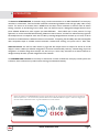
NOTE: The QUALITY and TRANSMISSION of the video signals depends on the characteristics and quality of the UTP cables and
Network Infrastructure . We recommend any Network Switches with 10GB POE IGMP v2.0 support . Tested and configured on
the below models. Downloads of how to guides available on Avenview website
www.avenview.com
Page 3
ontents
Before you start the installation of the HDMI Extender, please check the package contents.
1
X1
POWER ADAPTER (5V DC 2A) 5.5mm
2
Power
3
X1
USER MANUAL
X1
ation
•• Put the product in a level and stable location. If the product falls, it may cause damage or malfunction to components
within the casing.
•• Do not place the product in temperatures under 0˚C or over 50˚C. High humidity may also cause the unit to malfunction.
•• Use the DC power adapter with correct specifications supplied with the unit. If the improper power supply is used, this
may result in malfunction of the unit and may cause fire.
•• Do not twist or pull by force the ends of the UTP cable. It will cause malfunction.
NOTE
The QUALITY and TRANSMISSION of the video signals depends on the
characteristics and quality of the UTP cables. Higher resolutions and longer
transmission distances require low skew cables (<25ns/upto 300m) for best
performance. Unshielded CAT6 with metal RJ-45 connectors is recommended.
www.avenview.com
Page 4
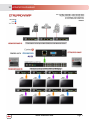
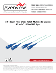
2.3 APPLICATION DIAGRAM
www.avenview.com
Page 5
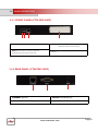
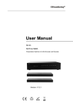
2.4 PANEL DESCRIPTION
2.4.1 FRONT PANEL (CTRLPRO-VWIP)
1
2
4
3
1. POWER: Red LED when device is powered on
2. ACTIVITY: BLUE LED: Device working properly
3. RESET: Reset device to factory default
4. IP ADDRES LABEL: Insert label here to identify unit IP
RED LED: Device is rebooting
address.
settings (press and hold 5 second)
2.4.2 REAR PANEL (CTRLPRO-VWIP)
1
1. ETHERNET: RJ45 Port
3
2
2. SERVICE: RS232 Debug Only
3. POWER: 5V/2A DC Power Supply Unit
www.avenview.com
Page|6
3.
ation
To setup Avenview CTRLPRO-VWIP please follow these steps for connecting to a device:
1. Turn off all devices including monitors / TV
2. Connect a HDMI source (such as a Blu-Ray Disc player or pC) to the Transmitter HDM-C6VWIp-S
3. Connect u SB cable to the pC (only if pC is the source and your extending k VM function)
4. Connect IR Blaster to device if applicable to the source IR Eye and 3.5mm male to TX
5. Connect CAT5/6 from TX to RX CAT5/6 port HDM-C6VWIp-R 330 feet away
6. Connect Combo u SB keyboard and Mouse Wireless dongle to control pC at Display end 330 feet away.
7. Connect IR Receiver to device if applicable to any visible surface and 3.5mm male to RX
8. Ensure all cable connections are secure and not loose
9. plug in 12V DC power (supplied).
10.power on HDMI Source
11.power on the HDMI display
Required ONly in Extending Dektop or laptop
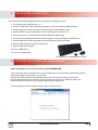
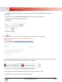
3.1 ACCESSING THE CTRLPRO-VWIP WEB INTERFACE
Follow steps below to access the web interface of the CTRLPRO-VWIP
1. Enter 192.168.11.243 into a web browser. For optimal performance, we recommend use of the latest versions of
Firefox, Opera, Safari, Internet Explorer 11 or Chrome.
Attention The default IP address of the CTRLPRO-VWIP is 192.168.11.243. To connect you must have a
network configured that allows this subnet or must set your PC to a 192.168.11.xxx address to connect. The
IP address of the IP Control Box can be changed through the System Settings page.
2. Enter a password (“admin” by default) and click Login to access the device.
www.avenview.com
Page 7
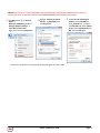
NOTE If you receive a ‘server unavailable’ system message after entering this address into your browser,
ensure your PC is on the same subnet as the CTRLPRO-VWIP box by following these steps:
1 Click Start menu, go to Control
Panel >
Network and Sharing center >
Change Adapter Settings >
Local Area Connection.
Right click and choose Properties.
2 Highlight Internet Protocol
Version 4 (TCP/IPv4) then
click Properties
3 Check Use the following IP
address, for the IP address
enter 192.168.11.x (if unsure
use 192.168.11.5) Enter subnet
mask number 255.255.0.0 Click
OK, then click OK again.
4. Return to your browser and try entering the default IP again (192.168.11.243)
www.avenview.com
Page 8
4. BASIC OPERATION
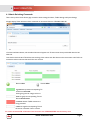
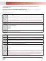
4.1 Matrix Switching Commands
Tabs at the top of the Home Screen page are used to access settings for Matrix, TX/RX Settings and System Settings.
All pages display Telnet API boxes where commands can be entered from the CTRLPRO-VWIP API.
Click the Load Matrix button, and the table of devices will appear with TX units across the top and the RX down the left
hand side.
Press the box that links each TX & RX to test switching of the video to each RX. Devices who’s names starts with EX131 are
transmitters where as devices that start EX141 are receivers
Device online
Device offline
A green bar represents corresponding TX
and RX are connected.
Clicking the green bar changes colour to
clear to signify the corresponding TX and
RX are disconnected.
A red bar denotes TX/RX connection is
being processed
A clear bar signifies corresponding TX and
RX are not connected. Click to connect.
To remove unwanted TX or RX units from the matrix the CTRLPRO-VWIP must be factory reset.
www.avenview.com
Page 9
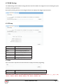
4.2 TX/RX Settings
The TX/RX Settings section enables IP settings and alias of each TX and RX to be configured as well as rebooting the system
and factory resetting the devices.
Get started by selecting the device to be configured from the list displayed and configure options as below:
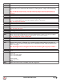
4.3 IP Setup
GUI Element
Description
Auto IP
Obtain IP address automatically
DHCP
IP address assigned by DHCP server
Static
IP address manually configured
IP Address
IP address of TX/RX
Subnet Mask
Subnet mask of TX/RX
Default Gateway
Default gateway of TX/RX.
4.4 Alias
Alias’ can be used in conjunction with API commands to simplify and shorten programming.
GUI Element
Description
Alias
Rename TX/RX alias for easier identification and use from API commands
Note: Alias cannot contain any of the following symbols or combinations of letters/numbers: ‘,’ ‘;’ ‘_’ ‘@’, ‘*’, ‘&’,
‘EX131’, ‘EX363’, ‘EX373’, ‘EX383’, ‘EX393’, ‘TX’, ‘EX141’, ‘EX403’, ‘RX’
www.avenview.com
Page 10
4.5 Commands
GUI Element
Description
Factory Default
Restore TX/RX to factory default settings
Reboot
Reboot TX/RX
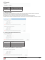
4.6 System Settings
System Settings contains the settings for the IP control box itself, comprising of two separate network connections for
communication with RX/TX devices and communication to the PC/control system.
Each setting must be on the same subnet as other devices to enable communication between all devices.
The default Auto IP setting is recommended for RX & TX communication - devices will use Bonjour to discover each other.
4.7 IP Setup (TX and RX Communication)
GUI Element
Description
IP Address
IP address for TX and RX communication
Subnet Mask
Subnet mask for TX and RX communication
Default Gateway
Default gateway for TX and RX communication
4.8 IP Setup (Telnet/Browser communication)
www.avenview.com
Page 11
GUI Element
Description
IP Address
IP address for Telnet client and web
Subnet Mask
Subnet mask for Telnet client and web
Default Gateway
Default gateway for Telnet client and web
4.9 Web Password
GUI Element
Description
Web Password
Login password for Web UI management page
Default password
“admin” can be used to restore to factory settings if the user password is unknown
4.10 Debug Log
NOTE: Debug files can only be used with the guidance of AVENVIEW support.
4.11 Commands
GUI Element
Description
Factory Default
Restore IP Control Box to factory default settings
Reboot
Reboot IP Control Box
Shutdown
Shutdown IP Control Box
www.avenview.com
Page 12
5.
CUSTOMISING THE UI
The CTRLPRO-VWIP web interface supports the creation of custom banners, page names & icons to be added to
specific pages.
To customise the UI, enter http://IPaddress/custom into a browser to display the page below.
Click the Browse button in the Banner column to change the main banner (marked in red box below).
Click the Browse button in the Icon column to change the icon in the upper left corner of the browser (marked in red box
below). You may need to clear the cache so that the icon can be displayed.
1 System name is the web page title - IP Control Box System by default.
2 Click Change to save the changes. Refresh the page to see the change take effect in the UI.
35 Restore button at the bottom restores to factory default settings.
www.avenview.com
Page 13
6. CTRLPTO-VWIP CONTROL PROTOCOL
The Telnet protocol can be used to send configuration settings, matrix switching and video wall commands to the
CTRLPRO-VWIP system.
Commands can only be issued to the CTRLPRO-VWIP by IP using port 23.
The default IP address of the CTRLPRO-VWIP is 192.168.11.243 – in default configuration commands should be sent
to this IP address.
Matrix Switching Control
Command
Matrix set TX1 RX1 RX2, TX2 RX3 RX4,...
Return
Matrix set: TX1 RX1 RX2, TX2 RX3 RX4,...
Note
Route one or Multiple TX on one or Multiple RX. Each individual TX and its routed RX or RX’s compose a record, and should be separated by a commas. Use NULL after a TX and any RX units from this TX will disconnect. Matrix commands cannot be sent when an RX is in video wall mode, first remove the RX from the video
wall or use the vw change command
E.g.: “matrix set Source1 Screen1 Screen2” sends TX with alias Source1 to RX’s with alias’ Screen1 & Screen2
Command
matrix get
Return
the connected TX/RX information with below
format matrix information:
TX1 RX1
TX2 RX3
TX2 RX4
....
Note
Obtain matrix information. Based on current TX/RX in the network, re-construct the network topology
and feedback to the third-party controller.
Video-Wall
Command
vw add vw-name n m tx
Return
videowall item vw-name create and assign tx to it
Note
Create a video wall configuration, n and assign a TX.
E.g.: “vw add wall1 2 2 Source1” creates a 2x2 video wall named “wall1” on the TX with the alias Source1.
Command
vw add vw-name n m tx
Return
videowall item vw-name removed
Note
Remove a video wall configuration.
E.g.: “vw rm wall1” removes wall1 configuration from the
TX
vw add vw-name tx1 x y rx2 x y
Command
Return
videowall item vw-name configuration added:
rx1 posion1
rx2 posion2
...
Note
Configure the video wall vw-name and add the corresponding RX’s in the given positions, this will set up many
RX and at once. Position (format): x y, represents a location, such as a 2 x 2 video-wall with 2 rows, and 2
columns.
E.g.: “vw add wall1 Screen1 1 1 Screen2 1 2 Screen3 2 1 Screen4 2 2” Sets the RX units with alias’ Screen 1 to 4,
to the noted x y positions in the video wall. Note a video wall by the name of wall1 must have already been
created using “vw add wall1 1 2 tx1” before this command can be used.
www.avenview.com
Page 15
Command
vw add vw-name layout n m TX RX11 RX12 RX13 RX1m RX21 ... RXnm
Return
videowall vw-name layout n m tx rx11 rx12 rx13 rx1m rx21 ... rxnm
Note
Add a video wall layout n rows and m columns, subsequently the RX are automatically assigned positions in
the video wall in order. The Parameter RX could be a ‘0’, indicating there is no change to the corresponding
RX.
E.g.: “vw add wall1 layout 2 2 Source1 Screen1 Screen2 Screen3 Screen4” Note this is a faster way to configure a video wall as it does not require a vw add command previously but is not as flexible as the previous
command.
Command
vw change rx tx
Return
videowall config change: rxhostname moved from vw-name and connect to txhostname
Note
Set RX to full-screen display of TX. Used for matrix switching in configurations that use video wall mode or to
remove an individual RX from the video wall and display a different or identical TX.
E.g.: “vw change Screen1 Source4”
Command
vw change vw-name tx-name
Return
videowall vw-name tx connect to txhostname
Note
Set all RX in the video wall to display another TX.
E.g.: “vw change wall1 input1
Command
vw bezelgap vw-name ow oh vw vh
Return
videowall vw-name’s bezelgap: xx xx xx xx
Note
Set the size of TV frame (video edge) to correct for large bezel screens. units are in mm (0.1cm). ow & oh =
overall width & height of display including the bezel, vw & vh = screen width and height.
E.g.: “vw bezelgap wall1 16100 9100 16000 9000”
Command
vw pictureparam vw-name h-shift v-shift h-scale v-scale tearing-delay rx1 rx2 rx3 ...
Return
set videowall vw-name’s pictureparam: xx xx xx xx xx to rx1 rx2 rx3 ...
Note
Configure the rx1/rx2/rx3 ... image shift. 1 unit = 8 pixels, a negative number indicates to move left or up).
Scale units = 1 Row or Columns / tearing delay units: µs, values between 10000~16000). If a parameter is 0 it
will not be changed.
E.g.: “vw pictureparam wall1 2 1 3 3 12500 Screen3 Screen4” will shift the image on screen 3 and 4 16 pix-els
down, 8 pixels right, whilst over-scaling by 3 rows and 3 columns and setting the tearing delay to 12500 µs.
Command
vw get
Return
video wall information: vwname1 TX1
row-number1 RX11 RX12..
row-number2 RX21RX22
… ...
vw-name2 TX2
row-number1 RX11
RX12… ...
Note
Obtain video wall information and feedback video wall configurations.
www.avenview.com
Page 16
Video-Wall 2
The vw2 is a special command set used for multi-host mode if the tearing delay command fails to resolve the tearing on a
video wall.
Command
vw2 add vw-name n m tx1 tx2 ... txn
Return
videowall2 item vw-name(n*m) create and assign tx1 tx2 ... txn to it
Note
Create a video wall configuration, and assign a TX for each row.
E.g.: “vw add wall1 2 2 Source1 Source2” Creates a 2x2 video wall using RX 1 for row one and TX2 for
row 2.
Command
vw2 add vw-name rx1 position rx2 position
Return
videowall2 item vw-name(n*m) configuration added:
rx1 position1
rx2 position2
...
Note
Configure the video wall vw-name and add the corresponding TX and RX.
E.g.: “vw2 add wall1 Screen1 1 1 Screen2 1 2 Screen3 2 1 Screen4 2 2” Sets the RX units with alias’
Screen 1 to 4, to the noted x y positions in the video wall. Note a video wall by the name of wall1 must
have already been created using “vw2 add wall1 2 2 tx1 tx2” before this command can be used.
Command
vw2 add vw-name layout n m TX1 RX11 RX12 … RXnm TX2 RX21 RX22 ... RXnm
Return
videowall2 vw-name layout n*m tx1 rx11 rx12 … rxnm rx1 tx2 rx21 ... rxnm
Note
Add a video wall layout n*m, subsequently the RX based on display order. The Parameter Rx could be character ‘0’, indicates no need to change the corresponding RX.
E.g.: “vw2 add wall1 layout 2 2 Source1 Screen1 Screen2 Source2 Screen3 Screen4” Creates a 2x2 video wall
using RX1 for row one and TX2 for row 2.
Command
vw2 rm vw-name
Return
videowall2 item vw-name removed
Note
Command
Remove a video wall configuration
E.g.: “vw2 rm wall1” removes wall1 configuration from the
TX
vw2 rm vw-name rx1 rx2 rx3
Return
videowall2 config change:remove rx1 rx2 rx3 hostname from vw-name
Note
Remove one or multiple rx from video wall.
E.g.: “vw2 rm wall1 Screen1” removes Screen1 from the video wall
Command
vw2 change vw-name tx1 tx2 tx3 txn
Return
videowall2 vw-name config change:
row1 tx1
row2 tx2
Note
Change the selected input or inputs of a video wall, replacing a tx alias with 0 means no change.
E.g.: “vw2 change wall1 Source1 0 Source3” Changes Wall1 inputs for row1 & row3 to rx1 & rx3
Command
vw2 reset tx
Return
videowall2 reset tx
Note
Remove the video wall configuration of this tx and display a complete picture. (If this tx is in video wall mode, it
will only display part of the picture.)
www.avenview.com
Page 17
Command
vw2 bezelgap vw-name ow oh vw vh [TX/RX1 TX/RX2 ...]
Return
videowall2 vw-name’s bezelgap: xx xx xx xx TX/RX1 TX/RX2 ...
Note
Set the size of TV frame (video edge). TX/RX1, TX/RX2 are optional, if null, the whole video wall is corrected,
otherwise individual one or a selection TX/RX units are corrected.
E.g.: “vw bezelgap wall1 16100 9100 16000 9000”
Command
w2 pictureparam vw-name h-shift v-shift h-scale v-scale [TX/RX1 TX/RX2 ...]
Return
set videowall2 vw-name’s pictureparam: xx xx xx xx TX/RX1 TX/RX2 ...
Note
Configure the rx1/rx2/rx3 ... image shift. 1 unit = 8 pixels, a negative number indicates to move left or up).
Scale units = 1 Row or Columns / tearing delay units: µs, values between 10000~16000). If a parameter is 0
it will not be changed. TX/RX1, TX/RX2 are optional, if null, the whole video wall is corrected, otherwise
individual one or a selection TX/RX units are corrected.
E.g.: “vw2 pictureparam wall1 2 1 3 3 12500 Screen3 Screen4” will shift the image on screen 3 and 4 16 pixels down, 8 pixels right, whilst over-scaling by 3 rows and 3 columns and setting the tearing delay to 12500
µs.
Command
vw2 get
Return
videowall2 information is:
vw-name1
row-number1 TX1 RX11 RX12 ...
row-number2 TX2 RX21
RX22 ... ...
vw-name2
row-number1 TX3 RX11 RX12 ...
Note
Obtain video wall information from IP Control Box.
www.avenview.com
Page 18
Serial
Pass-through the serial command.
Command
serial -b param –r {on|off} “command-string” hostname1 hostname2 ...
Return
serial command received: <cr>
serial -b param –r {on|off} “command-string” hostname1 hostname2 ...
Note
Configure devices hostname1, hostname2 to pass through serial command. Command-strings cannot con-tain
“ & ”.
-b param, configure the RS232 format of TX/RX and connected peripherals, including Baud rate, Data bits,
Parity and Stop bits. E.g.: -b 115200-8n1.
-r {on|off}, to turn on & off Carriage Return following the command-string.
hostname1 hostname2 ..., indicates the destination, could be multiple.
E.g.: “serial –b 9600-8n1 –r on !PWR01! Screen1 Screen2 Screen3” Sends the command !PWR01! to Screens
1, 2 & 3 with a carriage return at 9600 baud – 8 data bits, No parity, 1 Stop bit.
Command device-name message-body
Message Pass-through.
Command
Command device-name message-body
Return
Reply: the device process the command feedback
Note
Third-party controller or web ui pass through message-body to RX/TX.
Notification commands send by the CTRLPRO-VWIP
Notification of.
Command
N/A
Return
notify endpoint {+ | -} tx/rx tx/rx {- | +} tx/rx tx/rx ...
Note
Notify the third-party controller if any TX/RX is dropped out or added.
www.avenview.com
Page 19
7. INSTALLATION REFERENCE LOG
HDM-C6VWIP-S
TX#
IP ADDRESS
ALIAS
ADDITIONAL INFO
1
2
3
4
5
6
7
8
9
10
11
12
13
14
15
16
17
18
19
20
21
22
23
24
25
26
27
28
29
30
31
32
www.avenview.com
Page 20
HDM-C6VWIP-R
TX#
IP ADDRESS
ALIAS
ADDITIONAL INFO
1
2
3
4
5
6
7
8
9
10
11
12
13
14
15
16
17
18
19
20
21
22
23
24
25
26
27
28
29
30
31
32
www.avenview.com
Page 21
Avenview Warranty Certificate
AVENVIEW CORP. (“Avenview”) warrants Avenview-branded product(s) contained in the original packaging against defects in materials and workmanship when used
normally in accordance with Avenview's enclosed manual guidelines for a period of THREE (3) YEARS from the date of original retail purchase - Warranty Period. Avenview’s
published guidelines include but are not limited to information contained in technical specifications, user manuals and service communications.
LABOR: During the Warranty Period of THREE (3) YEARS, Avenview will repair or replace the product(s) at no cost using new or used parts equivalent to novel performance
and reliability if the product(s) is determined to have abide by Avenview’s published guidelines. Cost of Labor applicable to product(s) after Warranty Period. For labor costs,
please contact [email protected].
PARTS: During the Warranty Period of of THREE (3) YEARS, Avenview will supply new or rebuilt replacements in exchange for defective parts of the product(s) at no cost if
the product(s) is determined to have abide by Avenview’s published guidelines. Cost of Parts applicable to product(s) after Warranty Period. For part(s) costs, please contact
[email protected].
To obtain Warranty: (a) proof of purchase in the form of a bill of sale or receipted invoice reflecting that the registered product(s) is within warranty period must be presented
to obtain warranty service; (b) product(s) must be registered at time of purchase. Failure to do so will result in applicable parts and labor charges. Returning product(s) must
be shipped in Avenview’s original packaging or in packaging pertaining equal degree of protection to Avenview’s. Both Avenview and purchaser are responsible for freight
charges and brokerages when shipping the product(s) to the receiver.
NOT COVERED BY THIS WARRANTY
This warranty does not apply to any non-Avenview branded product(s); non-registered Avenview product(s). This warranty does not apply: (a) to cosmetic damage, including
but not limited to scratches, dents and broken cords; (b) to damage caused by use with another product; (c) to damage caused by accident, abuse, misuse, liquid contact, fire,
earthquake or other external cause; (d) to damage caused by operating the Avenview product(s) outside Avenview’s manuals or guidelines; (e) to damage caused by service
performed by anyone who is not a representative of Avenview or an Avenview authorized personnel; (f) to defects caused by normal wear and tear or otherwise due to the
normal aging of the Avenview product(s), or (g) if any serial number has been removed or defaced from the Avenview product(s).
AVENVIEW IS NOT LIABLE FOR DIRECT, SPECIAL, INCIDENTAL OR CONSEQUENTIAL DAMAGES RESULTING FROM ANY BREACH OF WARRANTY OR
CONDITION, OR UNDER ANY OTHER LEGAL THEORY, INCLUDING BUT NOT LIMITED TO LOSS OF USE; LOSS OF REVENUE; LOSS OF ACTUAL OR
ANTICIPATED PROFITS (INCLUDING LOSS OF PROFITS ON CONTRACTS); LOSS OF THE USE OF MONEY; LOSS OF ANTICIPATED SAVINGS; LOSS OF BUSINESS;
LOSS OF OPPORTUNITY; LOSS OF GOODWILL; LOSS OF REPUTATION; LOSS OF, DAMAGE TO, COMPROMISE OR CORRUPTION OF DATA; OR ANY INDIRECT
OR CONSEQUENTIAL LOSS OR DAMAGE REPAIR OR REPLACEMENT AS PROVIDED UNDER THIS WARRANTY IS THE EXCLUSIVE REMEDY OF THE CONSUMER.
Some states do not allow the inclusion or limitation of incidental or consequential damages, or allow limitations on duration implements of the Warranty Period; therefore the above limitations or
exclusions may not be applicable to you. This warranty gives you specific legal rights, and you may have other rights which vary from state to state.
275 Woodward Avenue, Kenmore, NY 14217
1.866.508.0269
www.avenview.com
AV Connectivity, Distribution And Beyond...
TECHNICAL SUPP ORT
USA Head Office
Office Avenview
Corp. 275 Woodward Avenue
K enmore, NY 14217
Phone: +1.716.218.4100 ext223
F ax: +1.866.387-8764
Email: [email protected]
Canada Sales
Avenview
151 Esna Park Drive, U nit 11 & 12
Markham, Ontario, L 3R 3B1
Phone: 1.905.907.0525
F ax: 1.866.387.8764
Email: [email protected]
Avenview Europe
Avenview Europe
Demkaweg 11
3555 HW U trecht
Netherlands
Phone: +31 (0)85 2100- 613
Email: [email protected]
Avenview Hong Kong
U nit 8, 6/F., K wai Cheong Centre,
50 K wai Cheong Road,
K wai Chung, N.T.
Hong K ong
Phone: 852-3575 9585
Email: [email protected]
Disclaimer
While every precaution has been taken in the preparation of this document, Avenview Inc. assumes no liability with respect to the operation or use of
Avenview hardware, software or other products and documentation described herein, for any act or omission of Avenview concerning such products or this
documentation, for any interruption of service, loss or interruption of business, loss of anticipatory profits, or for punitive, incidental or consequential damages
in connection with the furnishing, performance, or use of the Avenview hardware, software, or other products and documentation provided herein.
Avenview Inc. reserves the right to make changes without further notice to a product or system described herein to improve reliability, function or design.
With respect to Avenview products which this document relates, Avenview disclaims all express or implied warranties regarding such products, including but
not limited to, the implied warranties of merchantability, fitness for a particular purpose, and non-infringement.