Transcript
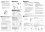
Welcome! Congratulations for having purchased your PowerCost Monitor™. This guide will show you how to install your PowerCost Monitor safely and start enjoying your electricity savings immediately. By following the instructions in this Installation Guide, you will: Ensure that your PowerCost Monitor Display Unit and Sensor Unit operate as intended. Install your Sensor Unit on your meter. Synchronize your Display and Sensor Units together. Be ready to setup your Display Unit by following the instructions in the Setup Guide. Innovative Energy Solutions Important Safety Precautions Install your Sensor Unit on a dry day and take all necessary safety precautions, more particularly if you need to use a ladder for installing the Sensor Unit. In addition, please read and apply the safety instructions below at all times. Do not immerse either PowerCost Monitor unit in any liquid. Do not drop or cause any sudden impact to either PowerCost Monitor unit. If disposing of the PowerCost Monitor, do so in accordance with your local waste disposal regulations. Do not attempt to repair the PowerCost Monitor yourself. Take precautions when handling batteries. They can cause injuries, burns, and/or property damage as a result of contact with metal objects, heat, and corrosive materials. A damaged LCD display may leak fluids that can be harmful to your health. If any fluid does leak from the Display Unit after you drop it accidentally, immediately wash it off with soap and water. Carefully read the instructions before using your PowerCost Monitor. Step 1: Verify the contents and basic operation 1 Verify that your box contains all these components, then store the packing materials in a safe place: • • • • • • • Display Unit Sensor Unit Rubber Shims (2) Clear Alignment Template (1) Installation Guide, Setup Guide and User Manual Alkaline “AA” Batteries (4) Installation DVD 2 Install the batteries in the Display Unit Remove the Display Unit battery cover on the back of the unit, insert two alkaline “AA” batteries in the orientation indicated and replace the cover. You hear several beeps in rapid succession. 3 Install the batteries in the Sensor Unit Open the Sensor Unit battery compartment by moving the cover latch to the unlocked position. Install the two AA alkaline batteries, with the battery closest to the Sensor Arm going in positive (+) end first. Close the cover and move the latch back to the locked position. The red STATUS indicator lights up. Step 2: Determine your meter type Your utility meter is most probably located outside your house and it looks like one of the pictures on these two pages. If your meter is one of the three types below, you can only install the Sensor Unit by following the instructions in the appropriate section in the supplied user guide Your meter looks like this… Your PowerCost Monitor™ Sensor Unit has been designed to fit on virtually any residential meter type, using its built-in clamping strap that goes over the meter dome. However, the installation procedure varies according to meter types. It is extremely important that you determine accurately what kind of meter is installed in your home before proceeding. Here are a few indications to help you. …with the Sensor Unit mounted Optical Port Front Optical Port LESS THAN 1½ inches from outer rim of dome. If in doubt, physically measure the distance. Electromechanical meters (with dials and a spinning disk with a black mark) Electronic meters (with a digital readout) See User Guide section 5.4 Electronic meters emit a light pulse signal through an optical port. The optical port can be located: On the front of the meter face On top of the meter. Press and hold the SYNC button on the front of the Display Unit until it beeps (approx. 3 seconds). The Display Unit displays this screen. Step 5 - Complete the installation When you are ready to install your PowerCost Monitor™ on your meter, you will need the following: This procedure synchronizes the Sensor Unit and Display Unit, enabling you to program the Display Unit. IMPORTANT: Please remember that your ultimate goal is to position the Sensor Head either inline with your electromechanical meter’s spinning disk, or directly above your electronic meter’s optical port. IMPORTANT: Wipe the meter glass dome clean with the damp cloth before proceeding. Your Sensor Unit is delivered ready to install on your meter. However, it is recommended you pull the latch cover up to open it and verify that the Sensor Arm is pushed in as far as it will go into the body of the Sensor Unit. 1: Find the picture on the left side that looks like your meter. The picture next to it shows how your sensor should look when properly mounted. If you determine that your meter is one of the two types below, you can follow the procedures in this quick start guide to install your Sensor Unit. Your meter looks like this… …with the Sensor Unit mounted 2: Electronic Meter Front Optical Port LESS THAN 1½ inches from outer rim of dome. If in doubt, physically measure the distance. See User Guide section 5.4 You have an electromechanical meter The PowerCost Monitor™ Quick Installation Guide Reset Button Tighten the hose clamp until the Sensor Unit is snug, but can move just enough to allow for slight adjustments. 2: If the STATUS indicator does not react as described in Step 1, reposition your Sensor Unit slightly and repeat Step 1. 3: Make sure the Display Unit is on. Press and hold the SYNC button on the front of the Display Unit until it beeps (approx. 3 seconds). The Display Unit goes into ID Mode and it begins to search for your Sensor Unit. 4: Press and release the RESET button on the battery cover of the Sensor Unit. The indicator light flashes and the Display Unit exits ID mode. 5: Tighten the hose clamp until the Sensor Unit cannot move easily. Do not over-tighten. Move the Sensor Unit assembly until the Sensor Arm is properly positioned on the meter: 1: Pull the latch cover upward to open it. 2: Extend the Sensor Arm to its full length by pulling on it. If you accidentally pull it out completely, push it back into the casing. Optical Port 3: Close the latch cover. Press and release the RESET button on the battery cover of the Sensor Unit. On an electromechanical meter, the red STATUS indicator on the Sensor Unit first lights up, then turns off and, within 45 seconds, it starts flashing once per revolution of the disk. On an electronic meter, the red STATUS indicator on the Sensor Unit first lights up, then starts flashing regularly and, within 45 seconds, you should also see an extra flash every now and then, at a rate that varies according to your electricity consumption. After adjusting the Sensor Arm length according to your meter type, fit the Sensor Unit over your utility meter as shown, so that the Sensor Head sits as close as possible to the front of the glass dome. On an electromechanical meter, the Sensor Head at the end of the Sensor Arm must be inline with the disk (use the line on the Sensor Arm as a reference) and centered from side-to-side. Electronic Meter Optical Port Electronic Meter Press and release the RESET button on the battery cover of the Sensor Unit. The Display Unit now displays this screen. 1: Electromechanical Meter 3: Electromechanical Meter This Guide Display Unit 1 large Flat Head screwdriver Stepping stool or ladder if your utility meter is located higher than eye level Clean damp cloth You have an electronic meter with the optical port on the face Optical Port 4 Synchronize the Display and Sensor Units This step ensures that both the Display Unit and Sensor Unit operate properly. Step 4 - Install your Sensor Unit The Sensor Unit has two main parts: the fixed body and the movable Sensor Arm. The Sensor Head is located at the end of the Sensor Arm. Perform one of the two procedures below according to your meter type, and then go to the next step. Electronic Meter There are two families of electrical meters: Step 3 - Prepare your Sensor Unit Top Optical Port On an electronic meter, the head at the end of the Sensor Arm must be located exactly above the optical port. Electronic Meter Front Optical Port AT LEAST 1½ inches from outer rim of dome. If in doubt, physically measure the distance. See User Guide section 5.5 6: You can now program your Display Unit by following the instructions in the Setup Guide. 187 Kenmount Road St. John’s, NL Canada A1B 3P9 www.bluelineinnovations.com Toll Free: (866) 607-2583 P/N: BLI-00194R003 © BlueLine Innovations Inc. PowerCost Monitor™ is a trademark of BlueLine Innovations Inc.