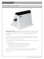
1
iR Media Connector
Infrared Media Connector
User Manual
iR Media Connector User Manual
CONGRATULATIONS!
Congratulations on your purchase of the Lightspeed™ IR Media Connector.
The iR Media Connector (iRMC) is designed to interface auxiliary audio sources,
such as computers, MP3 or DVD players with a Lightspeed infrared classroom
audio system.
The iRMC eliminates the need to run wires or cables from the audio source to the
amplifier unit. Simply position the iRMC near the audio source, plug it in and the
signal is transmitted to the amplifier wirelessly.
Like Lightspeed’s entire line of classroom audio systems, the iRMC is designed with
the teacher in mind.
• Accommodates up to three auxiliary audio sources
• Powered by a standard AC outlet or a computer USB port
• Automatically powers up when a signal is indicated
• A single master volume control for ease of use
The iRMC takes only minutes to set up and is an ideal accessory to the REDCAT,
no install system, as well as the entire line of infrared classroom audio systems
by Lightspeed.
iR Media Connector User Manual | i
iR Media Connector User Manual
SAFETY INSTRUCTIONS AND CERTIFICATIONS
CAUTION
RISK OF ELECTRIC SHOCK DO NOT OPEN
CAUTION: TO REDUCE THE RISK OF ELECTRIC SHOCK
DO NOT REMOVE COVER (OR BACK)
NO USER-SERVICEABLE PARTS INSIDE
REFER SERVICING TO QUALIFIED PERSONNEL
The lightning flash with arrowhead symbol
within an equilateral triangle is intended to
alert the user to the presence of uninsulated
“dangerous voltage” within the product’s
enclosure, that may be sufficient magnitude to
constitute a risk of electric shock.
The exclamation point within an equilateral
triangle is intended to alert the user to
the presence of important operating and
maintenance (servicing) instructions in the
literature accompanying the appliance.
CERTIFICATIONS
Complies with 72/23/EEC Low Voltage Directive
and 89/336/EEC Electromagnetic Compatibility
Directive. Compliance was demonstrated to the
following specifications as listed in the Official
Journal of the European Union:
EN 60950: Electrical Safety – A1:1993, A2:1993,
A3:1993, A4:1997
EN 55022: RF Emissions, Information
Technology Equipment
EN 55024: EMC Immunity Standard
EN 61000-3-2: Harmonics
EN 61000-3-3: Voltage Fluctuation
Lightspeed Technologies launched a formal
product recycle program in Europe that
complies with the European Union Directive
2002/96/EC on Waste Electrical and Electronic
Equipment (“WEEE Directive”). Please visit our
website at www.lightspeed-tek.com for more
information.
IR Media Connector is manufactured using
lead-free processes and is free of other
materials harmful to the environment. It
conforms to the most stringent new European
guidelines for consumer products (RoHS).
ii | iR Media Connector User Manual
1. Read Instructions—All the safety and
operation instructions should be read
before this Lightspeed product is operated.
2. Retain Instructions—The safety and
operating instructions should be kept for
future reference.
3. Heed Warning—All warnings on this
Lightspeed product and in these
instructions should be followed.
4. Follow Instructions—All operating and
other instructions should be followed.
5. Water and Moisture—This Lightspeed
product should not be used near water.
6. Heat—This Lightspeed product should be
situated away from heat sources such as
radiators, etc.
7. Power Sources—This Lightspeed product
should be connected to a power supply
only of the type described in the operation
instructions or as marked on this
Lightspeed product.
8. Power Cord Protection—Power supply
cords should be routed so that they are
not likely to be walked upon or pinched by
items placed upon or against them.
9. Object and Liquid Entry—Care should be
taken so that objects do not fall onto and
liquids are not spilled into the Lightspeed
product.
10.Damage Requiring Service—This
Lightspeed product should be serviced
only by qualified service personnel. The
user should not attempt to service this
Lightspeed product.
11.Prevent Electric Shock—Do not use this
polarized plug with an extension cord,
receptacle or other outlet unless the
blades can be fully inserted to prevent
blade exposure.
iR Media Connector User Manual
TABLE OF CONTENTS
iR Media Connector
Safety Instructions and Certifications................................................................................................... ii
SECTION 1: iRMC Overview................................................................................................................ 1
iRMC Components............................................................................................................................ 2
Front Panel Controls and Connections........................................................................................... 3
Rear Panel Controls and Connections............................................................................................. 4
SECTION 2: Set-up................................................................................................................................ 5
Unpacking Your iRMC....................................................................................................................... 6
Setting up the iR Media Connector................................................................................................. 7
Determine Set-up Method........................................................................................................... 7
Audio Integration.............................................................................................................................. 8
iR Media Connector Block Diagram............................................................................................ 8
Connecting the Power Supply......................................................................................................... 9
AC Power....................................................................................................................................... 9
USB Power..................................................................................................................................... 9
SECTION 3: Operation. ...................................................................................................................... 10
Initial Set-Up.................................................................................................................................... 11
Turn Off Second Microphone.................................................................................................... 11
Understanding the Operating Modes...................................................................................... 11
Volume Adjustment.................................................................................................................... 12
SECTION 4: Troubleshooting Guide and Warranty.......................................................................... 13
Troubleshooting Guide................................................................................................................... 14
iRMC Specifications........................................................................................................................ 15
Individual Components and Optional Accessories...................................................................... 15
Warranty Statement........................................................................................................................ 15
User Notes....................................................................................................................................... 16
iR Media Connector User Manual | iii
iR Media Connector User Manual
SECTION 1
iRMC Overview
1 | iRMedia Connector User Manual
iR Media Connector User Manual
IRMC COMPONENTS
Lightspeed iR Media Connector and Power Supply
USB Cable
Audio Cable Kit
Screws and Anchors for
optional wall mounting
Helpful Hint
Keep ALL packaging materials. If the system must be returned, using the original packing
material will be quick, convenient and prevent damage.
iR Media Connector User Manual | 2
iR Media Connector User Manual
FRONT PANEL CONTROLS AND CONNECTIONS
1. STATUS LIGHT: Indicates current state of the iR Media Connector. The light will glow amber
when in standby, and blue when it is transmitting a signal. For more information on the status
light, see page 12, Understanding the Status Light
2. VOLUME CONTROL: Controls the output volume of the iRMC. Factory pre-set for most
applications.
3. POWER BUTTON: Used to turn the iRMC off or on.
1
2
3
3 | iR Media Connector User Manual
iR Media Connector User Manual
REAR PANEL CONTROLS AND CONNECTIONS
1. Three Audio Inputs: Connect standard audio devices to any of the 3.5mm stereo inputs.
A provided cable allows connectivity to RCA stereo outputs
common on DVD players and televisions.
2. USB Power Input: Alternatively, use the
provided USB cable to power the iR
Media Connector from a
USB-enabled computer.
3. Power Cable Input:
When using an AC
outlet, plug the
power supply
(5V/1.0A) into
this jack.
1
2
3
Helpful Hint
Although rare, you may have
a Lightspeed system using the
alternate “Group 2” frequencies.
If this is the case, simply switch
the frequency selection switch
located on the bottom of
the iRMC to the appropriate
frequency.
iR Media Connector User Manual | 4
iR Media Connector User Manual
SECTION 2
Set-up
5 | iRMedia Connector User Manual
iR Media Connector User Manual
1. UNPACKING YOUR iRMC
Ensure that you have received all of the iRMC components.
Lightspeed iR Media Connector (iRMC) and Power Supply
USB Cable
Audio Cable Kit
Screws and Anchors for
optional wall mounting
iR Media Connector User Manual | 6
iR Media Connector User Manual
2. SETTING UP THE IR Media Connector
DETERMINE SET-UP METHOD
Choose a location for the iR Media
Connector that is convenient to the
audio source and power supply.
The iRMC can be placed on a counter
or wall mounted. Determine the
best location for your room. Use the
guidelines below when selecting the site.
Counter:
• 3-6 feet off of the ground to allow for
good transmission.
• Not enclosed in a cabinet or otherwise
obstructed.
Wall-mount:
• Recommended 4 feet off of the ground to
allow for unobstructed transmission and access
to controls.
• Recommended vertical mounting with volume
knob pointed up to prevent undue stress on
cables.
• Attach to the wall using the included mounting
screws and, if required, drywall anchors.
Helpful Hint
Although the iRMC does not require a direct line of sight to the
iR sensors, it functions best when no obstructions are between the
two devices.
7 | iR Media Connector User Manual
iR Media Connector User Manual
3. AUDIO INTEGRATION
iR Media Connector BLOCK DIAGRAM
The iR Media Connector is designed to integrate
multiple audio sources quickly and easily.
iR Media Connector User Manual | 8
iR Media Connector User Manual
4. CONNECTING THE POWER SUPPLY
The iR Media Connector can be powered in either of two ways:
• AC power from a nearby electrical outlet
• USB power from a computer
Use whichever power source is most convenient to the location of the iRMC.
AC POWER
1. Locate the DC port at the rear of
the iRMC.
2. Place the AC end of power cord
into an electrical outlet.
3. Place the DC end of power cord
into DC port at the rear of
the iRMC.
4. Press the power-on
button located on
the front of the iRMC.
USB POWER
If the primary audio source is a computer, it
might be more convenient to use the supplied
USB cable to power the iRMC from that
computer.
1. Insert USB cable into iRMC.
2. Insert USB cable into any available
USB port on the computer.
3. Press the power-on button located on the
front of the iRMC.
You have now set-up the iRMC and it is ready
to use.
Helpful Hint
Lightspeed provides an international power kit for use of the
iRMC outside of North America.
9 | iR Media Connector User Manual
iR Media Connector User Manual
SECTION 3
Operation
iR Media Connector User Manual | 10
iR Media Connector User Manual
INITIAL SET-UP
OFF
A CH B
The iR Media Connector uses
the same channel (channel B) as
the optional second microphone
(REDMIKE, LT71, or HM70). As a result,
they cannot be used simultaneously. If
you have a second microphone, turn
it off before transmitting audio from
the iRMC.
ON
1. TURN OFF SECOND MICROPHONE
2. Understanding the OPERATING MODES
The iRMC status light has three states:
When turned on the iRMC is in standby mode indicated by an amber light.
STANDBY
NOTE:
Five minutes after the audio signal has stopped, the iRMC will switch
to standby mode.
TRANSMITTING
POWERED OFF
A blue light indicates the iRMC is in the transmit mode.
No light indicates power off.
Power button toggles between
“Power On” and “Power Off.”
Helpful Hint
The iRMC consumes very little power when on standby. It is not
necessary to power off or unplug your iRMC at the end of the day.
11 | iR Media Connector User Manual
iR Media Connector User Manual
INITIAL SET-UP (continued)
3. VOLUME ADJUSTMENT
The iR Media Connector volume is preset for most standard audio signals. If you need to turn the
volume up or down, follow this procedure:
1. Adjust the volume at the computer, television, or other audio source if possible.
2. If the audio source does not have a volume control (such as many DVD players) adjust the
volume at the iRMC.
3. If the first two options do not give optimum volume level, the last place to adjust the volume
is the CH. B Volume on the classroom audio system (REDCAT or other).
Helpful Hint
If you adjust the CH B volume on the classroom audio system, you
will also be changing the volume for your second microphone. Return
the CH B volume knob to the original position before turning the
second microphone back on.
iR Media Connector User Manual | 12
iR Media Connector User Manual
SECTION 4
Troubleshooting Guide and Warranty
13 | iRMedia Connector User Manual
iR Media Connector User Manual
TROUBLESHOOTING GUIDE
No Audio
• Confirm that you are plugged into an AC power outlet or USB port.
• Check power light. If the light is off, press the power button.
• Confirm that all audio cables are fully inserted to the proper ports.
• Confirm that you are not using a Group 2 classroom audio system. If it is a
Group 2 system, move the switch on the bottom of the iR Media Connector to
the 3.7 frequency setting. A Group 2 system will be represented with a black
colored microphone.
• Relocate the iRMC so that the top of the unit is not obstructed.
Low Volume
• Check volume setting at the audio source.
• Check volume setting at the iRMC. For most situations the middle setting is
most appropriate, but adjust if necessary.
• Check CH B volume setting of the classroom audio system amplifier.
Fluctuating volume levels:
• The iRMC is designed with a volume limiter which prevents distortion due
to over-driving the speaker. • Turn down the volume of the audio source. Turn up iRMC volume as
needed.
Static and Audio Dropouts
• If using a second microphone, confirm that it is powered off.
• Make sure the infrared emitters on the top of the iRMC are not being covered
and the unit is in the open and not in a closet or cabinet.
If you review these instructions and still have questions, write down the serial number and model
number of your system and call Lightspeed Technical Services at 800.732.8999, 5 a.m. – 5 p.m. PST.
iR Media Connector User Manual | 14
iR Media Connector User Manual
IR MEDIA CONNECTOR SPECIFICATIONS
Carrier Frequencies........................................... 2.54 MHz and 3.7 MHz
Frequency Response......................................... 80 Hz to 10 kHz ±3 dB
Signal-to-noise Ratio......................................... >70 dB
Audio Distortion ............................................... <1%
Audio Inputs....................................................... Three (3) 3.5mm stereo jack
DC Power Input.................................................. 5 V / 1.0 Amp, 0.65mm coaxial barrel DC power jack
USB Power........................................................... 5 V mini-B USB connector
Mounting............................................................. wall or table-top
Dimensions (L x W x H)....................................... 4.25” x 3.375” x 4”
INDIVIDUAL COMPONENTS
Part Number
Description
IRMC
IR Media Connector with cables and power supply
PS-5V-1.0
Power supply for IR Media Connector
CA-MCPCKIT
iRMC Audio Cable Kit (includes USB cable)
PS-5V-1.0-INT
Power Supply for iRMC with International Plug Attachments
5-year Limited Warranty
Lightspeed Infrared Audio Systems and optional accessories are warranted against malfunction
due to defect in materials and workmanship for a period of five (5) years from date of purchase.
System components will be repaired or replaced at Lightspeed’s option. Rechargeable batteries and
connecting cables are guaranteed for one (1) year. Warranty does not extend to finish, appearance, or
malfunctions due to abuse or misuse. Repairs performed by other than Lightspeed Technologies will
void this warranty.
For warranty service, including return shipping labels, please contact Lightspeed’s Service
Department at 800.732.8999 / [email protected].
Our Service Department will handle all your repair/replacement needs.
800.732.8999, 5 a.m. – 5 p.m., PST
15 | iR Media Connector User Manual
iR Media Connector User Manual
USER NOTES
iR Media Connector User Manual | 16
iR Media Connector User Manual
USER NOTES
17 | iR Media Connector User Manual
MN0101US01-0
LIG H TSPEED TECH NOL OG I E S
11 509 SW He rman R d / Tua l a t i n, O R 9 7 0 6 2
T O LL FREE: 800.73 2 .8 9 9 9 / PHO N E : 5 0 3 .6 8 4 .5 5 3 8 / FAX : 503. 684. 3197
LI GHTS PEED-TEK.C O M
MN0101US01-0