1
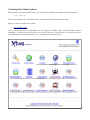
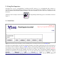
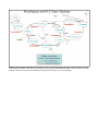
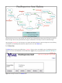
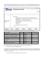
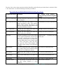
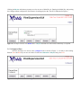
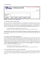
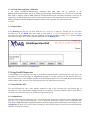
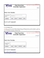
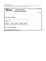
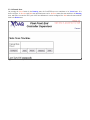
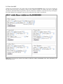
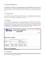
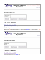
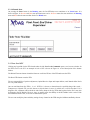
Pixel Online Software
User Manual
Version 1.1.0
Souvik Das
[email protected]
14 February 2007
Contents
1 Installing Pixel Online Software
1.1 Prerequisites
1.2 Setting Environment Variables
1.3 CVS Checkout
1.3.1 As a Developer
1.3.2 As a Guest
1.4 Checking out TTC Software
1.5 Compilation
1.6 Editing the Configuration XML File
2 Running Pixel Online Software
2.1 Using Pixel Supervisor
2.1.1 Initial State
2.1.2 Halted State
2.1.3 Configured State
2.1.4 Running State
2.1.4.1 Baseline Calibration Using Pixel Data
2.1.4.2 Address Level Calibration Using Pixel Data
2.1.4.3 Gain Calibration, Pixel Alive and S-Curve Calibrations
2.1.4.4 Clock Delay and Phase Calibration
2.1.5 Paused State
2.2 Using Pixel FEC Supervisor
2.2.1 State Machine GUI
2.2.1.1 Halted State
2.2.1.2 Configured State
2.2.1.3 Running State
2.2.1.4 Paused State
2.2.2 Low Level GUI
2.3 Using Pixel FED Supervisor
2.3.1 State Machine GUI
2.3.1.1 Halted State
2.3.1.2 Configured State
2.3.1.3 Running State
2.3.1.4 Paused State
2.3.2 Low Level GUI
3 Analysing Calibration Data
3.1 Pixel Alive
1. Installing Pixel Online Software
1.1 Prerequisites
DAQKit Version 03-09-02 must be installed. Instructions can be found at:
http://cmsdoc.cern.ch/cms/TRIDAS/DAQKit/pro/doc/html/index.html
A few questions may be asked during installation which should be answered thus:
CAENVME : The driver software for the CAEN PC-to-VME bridge ==> y/n/d : n
SBSVME : The driver software for the SBS PC-to-VME bridge ==> y/n/d : n
extern : External packages used by the XDAQ framework ==> y/n/d : y
xdaq coretools : The XDAQ core with essential tools ==> y/n/d : y
xdaq powerpack : Optional add-ons like memory pools, sentinel, xplore ==> y/n/d : y
xdaq worksuite : Tools to operate the fedkit (itools, pheaps, fedstreamer) ==> y/n/d : y
examples : XDAQ examples ==> y/n/d : y
jobcontrol : The application to control XDAQ Executives from RCMS ==> y/n/d : y
fedstreamer : The fedkit driver and the fedstreamer application. ==> y/n/d : n
itools : The generic pci access in itools. ==> y/n/d : n
hal : The Hardware Access Library (HAL) ==> y/n/d : y
jal : The JTAG Access Library (JHAL) ==> y/n/d : n
pheaps : Physical Memory allocation package. ==> y/n/d :
fedbuilder : FEDBuilder software (for the DAQ group only! read description!) ==> y/n/d : n
tts : software to operate the tts system ==> y/n/d : n
d2s : FED Emulator (GIII) based software (for DAQ group; read desctiption) ==> y/n/d : n
1.2 Setting Environment Variables
The following environment variables must be set if they haven't been already.
XDAQ_ROOT = /home/.../DAQKit/TriDAS
(Should be set if you have installed XDAQ)
LD_LIBRARY_PATH = $LD_LIBRARY_PATH:{$XDAQ_ROOT}/daq/hal/lib/linux/x86
LD_LIBRARY_PATH = $LD_LIBRARY_PATH:{$XDAQ_ROOT}/daq/xcept/lib/linux/x86
LD_LIBRARY_PATH = $LD_LIBRARY_PATH:{$XDAQ_ROOT}/daq/extern/xerces/linuxx86/lib
XDAQ_BASE = {$XDAQ_ROOT}
JAVA_HOME = /usr/java/j2sdk-1.4.2
(Should point to installation directory of Java SDK)
It may be convenient to have them in a file that runs on start up, like .bashrc if you prefer the bash shell.
1.3 CVS Checkout
1.3.1 CVS Checkout as a Developer
To check code out from our CVS repository as a developer on this project you will need registration as a CMS User, a
CERN Unix/AFS account and permissions for development from Karl Ecklund. You may use either Kerberos or SSH
to access the CVS repository.
To use Kerberos, set the environment variable:
CVSROOT = :kserver:isscvs.cern.ch:/local/reps/tridas
To use SSH, set the environment variables:
CVSROOT = :ext:{CERN User Name}@isscvs.cern.ch:/local/reps/tridas
CVS_RSH=/usr/bin/ssh
Now, from within the DAQKit directory, issue the following command:
cvs co -r POS_1_1_0 TriDAS/pixel
Once you enter the CERN password it may prompt you for, you should see the Pixel Online Software being checked
out. Please consult the Wiki page
https://twiki.cern.ch/twiki/bin/view/CMS/PixelOnlineSoftware
for detailed instructions.
1.3.2 CVS Checkout as a Guest
If you check code out as a guest you will not be allowed to modify or update the code. Set the following environment
variable:
CVSROOT = :pserver:[email protected]:/local/reps/tridas
From within the DAQKit directory, issue the following command and use 98passwd as the password:
cvs co -r POS_1_1_0 TriDAS/pixel
1.4 Installing TTC Software
Download the latest tarball of the Trigger and Timing Circuit Software from
http://cmsdoc.cern.ch/cms/TRIDAS/ttc/modules/software/TTCSoftware-5.14.tgz
into the directory $XDAQ_ROOT. Untar it parallel to the TriDAS/pixel directory using the command:
tar -xzvf TTCSoftware-5.14.tgz
This should create the directory TriDAS/TTCSoftware. Enter that directory using
cd TTCSoftware
and run the script:
./configure
Answer the questions (the defaults are usually fine). Then build the software by issuing the command:
make
This may take a few minutes to compile.
1.5 Compilation
From within the $XDAQ_ROOT/pixel directory, issue the following command:
make Set=pixel
1.6 Editing the Configuration XML File
The XML file at
$XDAQ_ROOT/pixel/XDAQConfiguration/ConfigurationNoRU.xml
is used by the XDAQ process in this version to load the Pixel Online Software applications. It needs to be edited as
follows:
The <xc:Context> tag on line 5 has an attribute url which needs to point to the HTTP port XDAQ applications listed
within it will be accessed from. It could be http://localhost:1973/
The <Configuration> tag on line 29 contains a path to the file TTCciConfiguration.txt. It cannot use an environment
variable and must for now be corrected manually to point to
$XDAQ_ROOT/pixel/PixelTTCSupervisor/TTCciConfiguration.txt
2. Running Pixel Online Software
Having built the Pixel Online Software Suite, go to the directory TriDAS/pixel/PixelRun and run the shell script:
./run_noRU.sh
This starts the XDAQ process with all the present components of the Pixel Online Software Suite.
Point a web browser window to the website:
http://localhost:1973/
and you should gain access to HyperDAQ, the web interface of XDAQ, with all the Pixel Online Software
applications – PixelSupervisorGUI, PixelSupervisor, PixelTTCSupervisor, PixelLTCSupervisor, PixelFECSupervisor,
PixelTKFECSupervisor and PixelFEDSupervisor – loaded into it as shown in Figure 1.
Figure 1. Screen shot of HyperDAQ
2.1 Using Pixel Supervisor
PixelSupervisor is not a web-application. PixelSupervisorGUI, however, is a web-application that connects to
PixelSupervisor using SOAP messages and may be used as one of its graphical user interfaces. PixelSupervisor can
also be interfaced with RCMS Function Managers and other interfaces, but that will not be discussed in this
document.
Clicking on the PixelSupervisorGUI icon
Figure 2.
in the HyperDAQ should bring up the web-interface shown in
2.1.1 Initial State
Figure 2. Screen shot of the PixelSupervisorGUI starting screen. PixelSupervisorGUI is in its Initial state.
PixelSupervisor and PixelSupervisorGUI are both state machines, as are all the other Supervisors. The current state of
PixelSupervisorGUI as shown in Figure 2 is Initial. The keys represent all possible inputs that can be received by the
state machine. Some of them are disabled while the others are enabled. The enabled key(s), in this case Initialise,
symbolise(s) the input(s) that the state machine can accept in its current state. The full state machine diagram of
PixelSupervisorGUI may be represented by Figure 3. It is a part of the finite state machine outlined in the Level 1
Function
Managers
CMS
Internal
Note
found
at
http://cmsdoc.cern.ch/TriDAS/RCMS/Docs/Manuals/manuals/level1FMFSM_1.5.pdf . The state machine diagram of
PixelSupervisor may be represented by Figure 4.
Figure 3. State machine definition of PixelSupervisorGUI. All ellipses represent states. Words in black represent
commands from RCMS or the Web GUI. Words in green represent commands passed down to PixelSupervisor's state
machine. Words in red represent commands passed up from PixelSupervisor's state machine.
Figure 4. State machine of PixelSupervisor. Solid ellipses represent states. Dashed rectangles represent state
transition functions. Green words represent state machine input commands passed down from PixelSupervisorGUI as
SOAP messages. Red words represent SOAP messages returned back to PixelSupervisorGUI as SOAP messages.
On pressing the Initialise key, the PixelSupervisor gathers information about the other local supervisors in the XDAQ
environment in its Initialising state transition, and proceeds to rest at the Halted state.
2.1.2 Halted State
The Halted state has only one possible input, Configure. However, there are multiple ways of configuring the Pixel
Detector. As shown in the illustration for the Halted state, Figure 5, they are grouped under Calibration and Physics
Runs.
Figure 5. PixelSupervisorGUI in its Halted state.
On clicking the Calibration radio button, the menu drops down to reveal several possible calibrations as shown in
Figure 6, one of which must be chosen and the Configure button pressed. Every calibration is associated with a
Global Key, a FED Control Register setting and a FED Mode Register setting. The association is specified in Table 1.
Figure 5. PixelSupervisorGUI in its Halted state, displaying a list of all possible Calibration Runs.
Calibration Type
Global Key FED Control Register FED Mode Register
FED Baseline Correction Using Test-DACs
0
0x7000f
0x0
FED Address Level Calibration Using Test-DACs 0
0x7000f
0x0
FED Baseline Correction Using Pixel Data
1
0x70019
0x0
FED Address Level Calibration Using Pixel Data 3
0x70019
0x0
Gain Calibration
4
0x70010
0x8
Pixel Alive!
5
0x70010
0x8
S-Curve
6
0x70010
0x8
Clock Delay and Phase Calibration
1
0x70019
0x0
Table 1. Global Keys and FED Control and Mode Register settings associated with different Calibration Types
All configuration information are loaded from files in this version. They exist in the folder:
$XDAQ_ROOT/pixel/PixelConfigDataExamples
Every Global Key is associated with a Detector Configuration, Name Translation Table, FED Configuration, FEC
Configuration, FED Card, TBM Settings, DAC Settings, Mask Settings and Trim Settings. If the Global Key
corresponds to a Calibration (i.e., not Physics), then a Calibration Object is also associated with the Global Key. This
association is specified in the file:
$XDAQ_ROOT/pixel/PixelConfigDataExamples/configuration.txt
The roles of the various objects associated with the Global Key and the files they are loaded from is outlined in Table
2. The “Panel name” use the Pixel Naming Convention prescribed in
https://docdb.fnal.gov/CMS/DocDB/0012/001205/001/naming_doc_V0.8.ppt
Configuration Object
Description
File Loaded From Relative to
$XDAQ_ROOT/pixel/PixelConfigDataE
xamples/
Detector Configuration Specifies which parts of the detector are going detconfig/{version #}/detectconfig.dat
to be configured.
Name Translation Table Associates Read Out Chip names (in CMS nametranslation/{version #}/translation.dat
naming convention) to their FEC numbers,
mFECs, mFEC channels, hub addresses, port
addresses, FEC ROC IDs, FED numbers, FED
channels and FED ROC numbers
FEC Configuration
Specifies the crate number and VME base fecconfig/{version #}/fecconfig.dat
address in that crate of all FECs
FED Configuration
Specifies the crate number and VME base fedconfig/{version #}/fedconfig.dat
address in that crate of all FEDs
FED Card
Specifies all settings for a given FED. Optical fedcard/{version
receiver capacitor adjustment, optical receiver number}.dat
input offset, optical receiver output offset,
offset DACs for all channels, clock phase bits,
ROC and TBM address levels, channel enable
bits, TTCrx coarse delay, TTCrx fine delay,
ADC gain bits, FED Control Register and
FED Mode register settings are all included in
this object
TBM Settings
Stores the Analog Input Bias, Analog Output tbm/{version #}/{Panel name}.dat
Bias, Analog Output Gain and Mode (Single
or Dual) for every TBM in the detector
DAC Settings
Stores all the DAC settings for all Read Out dac/{version #}/{Panel name}.dat
Chips
Mask Settings
Stores all the Mask Bits for all Read Out mask/{version #}/{Panel name}.dat
Chips
Trim Settings
Stores all the Trim Bits for all Read Out Chips trim/{version #}/{Panel name}.dat
Calibration Object
#}/params_fed_{FED
Stores the patterns of pixels that will be fired calib/{version #}/calib.dat
and DAC settings changed in a given
calibration
Table 2. Various objects used to configure the Pixel Detector for Calibration and Physics running.
Clicking the Physics radio button presents a text box to enter a Global Key in. Entering the Global Key and pressing
the Configure button configures the Pixel Detector for taking physics data. The GUI is illustrated in Figure 6.
Figure 6. PixelSupervisorGUI in its Halted state. A Physics Run has been chosen and a Global Key is requested.
2.1.3 Configured State
Once the PixelSupervisor arrives at the Configured state as shown in Figure 7, it is ready to start running.
Both the Start and Halt keys can now be clicked. To start the Calibration or Physics Run, press Start.
Figure 7. PixelSupervisorGUI in its Configured state.
2.1.4 Running State
Figure 8. PixelSupervisorGUI in its Running state.
2.1.3.1 Baseline Calibration Using Pixel Data
Observe the console that is running the XDAQ process with PixelFEDSupervisor loaded. Note that it tries to centre
the Black address level on every FED channel around 512┴5 by changing the Optical Receiver Input Offsets and the
Channel Offset DACs. Once the Black levels of all channels have been centred, a new FED Card file,
params_fed_{FED number}.dat will be written in the $XDAQ_ROOT/pixel/PixelRun area. To use this file for the
next time you press Configure, move it to the $XDAQ_ROOT/pixel/PixelConfigDataExamples/fedcard/ area with:
mv $XDAQ_ROOT/pixel/PixelRun/params_fed_{FED number}.dat
$XDAQ_ROOT/pixel/PixelConfigDataExamples/fedcard/{version #}/params_fed_{FED number}.dat
One Optical Receiver Input controls the level of 12 FED channels while one Channel Offset DAC controls the level of
one FED channel. For this reason, it may sometimes not be possible to solve widely separated Black levels on
different channels. In such cases the user will be alerted and no new FED Card file params_fed_{FED number}.dat
will be written.
2.1.3.2 Address Level Calibration Using Pixel Data
Observe the console that is running the XDAQ process with PixelFEDSupervisor loaded. Note that it prints out the
number of TBM Address Level peaks found per FED channel. The algorithm checks to make sure there are exactly 4
peaks and it recommends threshold levels for the TBM based on them. If a recommended threshold level falls within 5
standard deviations of any peak, the user is warned and no FED Card file is written. Similarly, the Address Levels for
all Read Out Chips are printed out and threshold levels recommended. Once again, it is required that all recommended
threshold levels lie beyond 5 standard deviations of each peak. If all criteria are met, the FED Card file will be written
in the $XDAQ_ROOT/pixel/PixelRun area and may be moved manually to its place in
$XDAQ_ROOT/pixel/PixelConfigDataExamples using:
mv $XDAQ_ROOT/pixel/PixelRun/params_fed_{FED number}.dat
$XDAQ_ROOT/pixel/PixelConfigDataExamples/fedcard/{version #}/params_fed_{FED number}.dat
2.1.3.3 Gain Calibration, Pixel Alive and S-Curve Calibrations
A file called GainCalibration.dmp containing FED Raw Data will be output in the $XDAQ_ROOT/pixel/PixelRun
area of the XDAQ process running PixelFEDSupervisor. This may be analysed using Root scripts written for the job
in conjuction with the $XDAQ_ROOT/pixel/PixelConfigDataExamples/calib/{version #}/calib.dat file used to
produce it.
2.1.3.4 Clock Phase and Delay Calibration
A file called ClockPhaseCalibration.dmp containing FED Raw Data will be generated in the
$XDAQ_ROOT/pixel/PixelRun area of the XDAQ process running PixelFEDSupervisor. This may be run through
Root scripts to produce graphs of TBM signals for all FED channels for all clock phases and delays. Those may be
inspected by eye and an appropriate value for phases and delays chosen. The values need to be directly edited into
$XDAQ_ROOT/pixel/PixelConfigDataExamples/fedcard/{version #}/params_fed_{FED number}.dat
as of now.
2.1.4 Paused State
In the Running state the user can press either the Halt or the Pause input key. Pressing the Halt key takes
PixelSupervisor to the Halted state from which it must again be Configured. Pressing the Pause key takes
PixelSupervisor to the Paused state. If it was configured for a Calibration Run, pressing Resume from the Paused
state makes PixelSupervisor run the calibration again and enter its Running state.
Figure 9. PixelSupervisorGUI in its Paused state.
2.2 Using PixelFECSupervisor
A PixelFECSupervisor supervises one crate of Front End Controller boards. PixelFECSupervisor may be run by
PixelSupervior via SOAP messages, or independently through its own web interface. Its web interface offers two
levels of interactivity: A state machine GUI that issues commands to all FECs in its crate while the user steps through
its state machine states, and a Low Level GUI that gives the user control down to the pixels.
2.2.1 State Machine GUI
The PixelFECSupervisor has a state machine identical to that of the PixelSupervisor and follows that of
PixelSupervisor. If its state machine is triggered using its web interface, care must be taken to return it to the state of
PixelSupervisor before PixelSupervisor is allowed to regain control of it.
2.2.1.1 Halted State
This is the initial state of PixelFECSupervisor. As shown in Figure 10, the user is allowed to enter a Global Key and
press the Configure button. On pressing the Configure button, the Global Key is used to retrieve configuration data
from PixelConfigDataExamples and download them to the FEC hardware while transitioning the state machine to the
Configured state. The Low Level GUI is not accessible yet as the PixelFECSupervisor has not retrieved the hardware
addresses of the FECs it controls.
Figure 10. PixelFECSupervisor in its Halted state
2.2.1.2 Configured State
Halt and Start are the two state machine input keys that are enabled in this state, as shown in Figure 11. The Low
Level GUI displays a list of FECs with their VME base addresses. Clicking on any opens a new browser window with
the Low Level GUI corresponding to that FEC board.
Figure 11. Configured state of PixelFECSupervisor. The Low Level GUI for individual FEC boards is available.
2.2.1.3 Running State
On pressing the Start button, the PixelFECSupervisor transitions to its Running state. It is shown in Figure 12. Pause
and Halt state input buttons are active. The Low Level GUI is accessible.
Figure 12. PixelFECSupervisor in its Running state.
2.2.1.4 Paused State
On pressing the Pause button in the Running state, the PixelFECSupervisor transitions to its Paused state. It is
shown in Figure 13. Resume and Halt state input buttons are active. Resume returns the state machine to its Running
state, and hence executes the FEC's part of the last calibration it was last configured for! Halt takes the state machine
back to its Halted state.
Figure 13. PixelFECSupervisor in its Paused state.
2.2.2 Low Level GUI
Clicking any hyperlink for the FEC boards under the title Low Level Commands opens a new browser window for
the FEC's Low Level GUI. An example of such a GUI is shown in Figure 14. It allows the user to send TBM
commands to individual TBMs, Program DAC and Clear Calibration commands to each Read Out Chip, and Program
Pixel and Calibrate Pixel commands to any pixel of any Read Out Chip within its jurisdiction.
Figure 14. Low Level GUI for the FEC board at VME base address 0x30000000 of the crate controlled by the
PixelFECSupervisor.
2.3 Using Pixel FED Supervisor
A PixelFEDSupervisor supervises one crate of Front End Driver boards. PixelFEDSupervisor may be run by
PixelSupervior via SOAP messages, or independently through its own web interface. Its web interface offers two
levels of interactivity: A state machine GUI that issues commands to all FEDs in its crate while the user steps through
its state machine states, and a Low Level GUI that allows the user to adjust various settings on any FED board in the
crate.
2.3.1 State Machine GUI
The PixelFEDSupervisor has a state machine identical to that of the PixelSupervisor and follows that of
PixelSupervisor. If its state machine is triggered using its web interface, care must be taken to return it to the state of
PixelSupervisor before PixelSupervisor is allowed to regain control of it.
2.3.1.1 Halted State
This is the initial state of PixelFEDSupervisor. As shown in Figure 15, the user is allowed to enter a Global Key, a
value for the FED Control Register, and a value for the FED Mode Register before pressing the Configure button. On
pressing the Configure button, the Global Key is used to retrieve configuration data from PixelConfigDataExamples
and download them to the FED hardware along with the FED Control and Mode Register settings. The state machine
is also transitioned to the Configured state. The Low Level GUI is not accessible in the Halted state as the
PixelFEDSupervisor has not yet retrieved the hardware addresses of the FEDs it controls.
Figure 15. PixelFEDSupervisor in its Halted state.
2.3.1.2 Configured State
Halt and Start are the two state machine input keys that are enabled in this state, as shown in Figure 16. The Low
Level GUI displays a list of FEDs with their VME base addresses. Clicking on any opens a new browser window with
the Low Level GUI corresponding to that FED board.
Figure 16. PixelFEDSupervisor in its Configured state. The Low Level GUI is now accessible.
2.3.1.3 Running State
On pressing the Start button, the PixelFEDSupervisor transitions to its Running state. It is shown in Figure 17. Pause
and Halt state input buttons are active. The Low Level GUI is accessible.
Figure 17. PixelFEDSupervisor in its Running state.
2.3.1.4 Paused State
On pressing the Pause button in the Running state, the PixelFEDSupervisor transitions to its Paused state. It is
shown in Figure 18. Resume and Halt state input buttons are active. Resume returns the state machine to its Running
state and Halt takes the state machine back to its Halted state.
Figure 18. PixelFEDSupervisor in its Paused state.
2.3.2 Low Level GUI
Clicking any hyperlink for the FED boards under the title Low Level Commands opens a new browser window for
the FED's Low Level GUI. An example of such a GUI is shown in Figure 19. A brief description of the buttons
follows.
The Reload Firmware button reloads the firmware on all four FPGAs of the FED and resets the FED.
The Reset FED button resets the FED.
The user can modify the Capacitor Adjustment, Optical Receiver Input and Output Offsets, and Channel Offset DACs
for every FED channel.
One can read data from Spy FIFO 1, 2 or 3. If FIFO 1 is chosen, a channel must be specified along with a mode –
Transparent or Normal. One can also choose to ship the data to screen, in which case it will be decoded. If it is
shipped to file, a filename will be asked for and a binary dump of the Spy FIFO data be placed in the file. It may also
be shipped to the RU Builder. However, since we cannot ensure the stability of the RU Builder in this version of the
Pixel Online Software suite, we do not recommend this option.
The user can modify the phase and delay settings for any channel on the FED using the SetPhasesAndDelays button.
Figure 19. Low Level GUI for the FED board at VME base address 0x1c000000 of the crate controlled by the
PixelFEDSupervisor.
3. Analysing Calibration Data
Analysis of the output from Pixel Online Software calibrations is currently implemented in root scripts.
3.1 Pixel Alive
Copy the calib file used to do this calibration to:
$XDAQ_ROOT/pixel/PixelRun
In this directory, run root using:
root -l
Once inside root, call the function:
pixel_alive_labc();
You should get a Postscript file for every FED channel. Open them using a postscript viewer to see the Pixel Alive
plots for all the Read Out Chips.