1
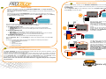
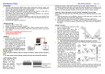
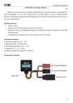
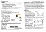
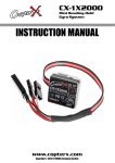
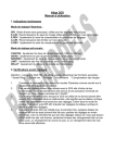
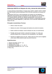
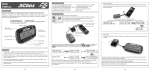
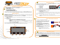
BATTERY MONITOR Connect the LiPo balance connector to the BATTERY CONNECTOR on the Viper ProGauge. Align the ground line to the bottom pin. The LCD screen will display the main menu: INTRODUCTION/FEATURES The Viper ProGauge is a revolutionary innovation that gives you every function you need in one pocket-sized box. You can use the ProGauge as: ▪ ▪ ▪ ▪ ▪ A Li-Po Battery Monitor A Servo Tester An Input PPM Signal Monitor A Propeller RPM Tachometer A Viper Device Programming Card Battery Monitor Link Device Servo Tester Tachometer PPM Monitor 2S~6S Li-Po Pack Use the Up/Down Key on the ProGauge to select the “Battery Monitor” option, press OK Key to enter the option. The Battery Monitor will display information about the battery on two pages. The first page displays the following readings: With an easy-to-read user interface and straightforward logic, the Viper ProGauge offers the most all-in-one functions, the easiest setup and the smallest size of any device on the market. USER INTERFACE A large 2x16 character LCD screen shows you all the information you need for each of the ProGauge’s many functions. Four buttons located beneath the display make it easy to enter information, make adjustments and find the right selection. There are two connectors on your ProGauge. 1. BATTERY CONNECTOR 7-pin connector that connects to a LiPo battery pack (up to 6S) via a LiPo balance connector 2. I/O CONNECTOR 3-pin connector for PPM I/O that connects to the following devices. Servo when you use the ProGauge as a Servo Tester. Receiver RX connector when you use the ProGauge as an Input PPM Signal Monitor. V-Port on any Viper product when you use the ProGauge as a programming card for any Viper Device. You can supply power to the Viper ProGauge through these ports when you use the Servo Tester, Propeller RPM Tachometer, or Viper Device Programming Card functions. PPM Signal Knob Press the Up/Down Key to see the second page. These readings are displayed on the second page: The exact voltage of each cell – up to 4 cells per page The cell with the highest voltage is indicated with an upper line symbol after the cell number. INPUT PPM SIGNAL MONITOR Turn on the corresponding transmitter Use a female to female servo extension cable to connect a radio receiver (any channel and with BEC power on) to the I/O Connector of the Viper ProGauge The LCD screen will display the main menu. Use Up/Down Key on the ProGauge to select the “PPM Monitor” option. Press the OK Key to enter the option. The ProGauge measures the PPM signal from the connected receiver. The LCD screen shows the following information: I/O Connector Total number of cells Total voltage Highest and lowest voltage cells The voltage difference between the highest-voltage and lowest-voltage cells Receiver ESC To Motor Battery Output voltage from the receiver Receiver’s PPM signal width and frequency Battery Connector Propeller Viper Service Policy RPM Sensor Escape Up Down OK Key Key Key Key ▪Your Viper ProGauge comes with a one-year (365 days) limited warranty that covers all parts and labor to repair any malfunctions under proper usage of the product. ▪All requests for warranty service require the original proof of purchase showing the item, date, price, and dealer info. ▪For service inquiries, please visit www.viper-rc.com and follow the service process for the quickest turnaround time. ▪For all technical questions, please visit www.viper-rc.com for the corresponding FAQ, or e-mail your question to [email protected]. PROPELLER RPM TACHOMETER SERVO TESTER Connect a LiPo battery (2S~6S) to the BATTERY CONNECTOR on the Viper ProGauge. Align the ground line to the bottom pin. The system will automatically regulate the output voltage to 5.0V to the I/O Connector for the Servo Tester. Connect the servo to the I/O CONNECTOR. The LCD screen will display the main menu. Use the Up/Down Key on the ProGauge to select the “Servo Tester” option, press OK Key to display the Servo Tester page. Connect a LiPo battery (2S~6S) to the BATTERY CONNECTOR, or use a female to female servo extension cable to connect a radio receiver with the power on (any channel) to the ProGauge’s I/ O CONNECTOR. Use the Up/Down Key on the ProGauge to select the “Propeller RPM Tachometer” option. Press OK Key to enter the option. 2S~6S Li-Po Pack 2S~6S Li-Po Pack The Servo Tester function has three settings. Press OK Key to enter the setup page from the Servo Tester main page. The following settings are available: 1. Set SWING/NORMAL Mode SWING Mode will send out a signal to make the servo swing automatically. NORMAL Mode allows you to turn the PPM Signal Knob to make the servo swing manually. 2. Set WIDE/NARROW Band Wide Band is neutral 1520us. Use this setting for most servos. Narrow Band is neutral 760us. This is for exceptionally fast servos like the Futaba S9251/S9256. Always check your servo specifications before setup. 3. Set NORMAL/EXTRA Range This allows the ProGauge to send out an extended PPM signal range. Use the Up/Down Key on the ProGauge to select each desired setting, and press OK Key to set. On the Servo Tester main page, the LCD screen displays the following information: WIDE/NARROW Band indication Servo swing time Voltage Servo travel position Peak current draw To ESC Set the correct number of blades by using the Up/Down/OK Keys. Point the propeller RPM sensor toward the spinning blades to get the RPM reading. The LCD screen displays the peak RPM measured by the sensor. Another way to use the tachometer function is to simply connect the ESC RX connector to the ProGauge’s I/O CONNECTOR when the ESC is connected to a battery. To Motor Battery To ESC VIPER DEVICE PROGRAM CARD The BEC power from the ESC will be power on the Viper ProGauge and enable the Propeller RPM Tachometer function. Turning the PPM Signal Knob will simulate the throttle signal for the ESC to turn the propeller. This allows you to easily measure the RPM without attaching an additional battery to the ProGuage. Plus, turning the PPM Signal Knob is safer than moving the throttle stick on your transmitter The Viper ProGauge can act as a programming interface with all Viper electronic products, such as electronic speed controllers and helicopter gyros. Properly connect the power source to the ESC or other device that you wish to program. Connect the V-Port on the Viper device to the ProGauge using the corresponding cable supplied with the product. To Motor Battery Use the Up/Down Key on the ProGauge to select the “Link Device” option. Press OK Key to enter the option. The LCD screen will display all available setup options for the linked device. Please refer to the user manual of the linked device for suggested setups and corresponding parameters. www.viper-rc.com Rev A1.6 .08262010