1
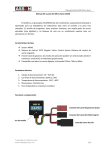
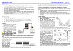
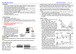
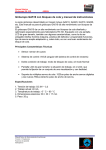
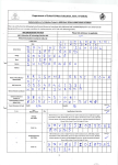
HELICOX TG‐1 INSTRUCTION MANUAL 1. Introduction TG-1 is a 3 axis gyro with small volume, light weight and advanced performance. It is mainly used in R/C
helicopter without a flybar. It also can be used as an advanced gyro for tail control separately. Its
high-speed processor can process the signal with high frequency and control the helicopter accurately. It
can be easily programmed by the G-BOX (sold separately), and can work well with both electric and nitro
R/C helicopters.
2. Specification Dimensions: 38.2mm*26.2mm*13mm
Weight: 20g (metal case, cables and connectors included)
Operating voltage: DC 3.5V-10V
Operating current drain: 60mA
Operating temperature:-10℃~50℃
Maximal angular velocity: 800 degrees/sec
Tail servo compatibility: 1.52ms analog servo, 1.52ms digital servo, 760us digital servo, 960us digital
servo
Swash plate servo compatibility: 1.52ms analog servo, 1.52ms digital servo
Radio compatibility: PPM, PCM, 2.4G
3. Connections ◆ Connect to receiver
◆ Connect to servos
Connect the tail servo to CH4 and connect swashplate servos to CH1, CH2, CH3 according to the
type of the swashplate.
4. LED indication Steady red
Gyro is in AVCS mode
Steady blue
Gyro is in Normal mode
Steady red and blue
Gyro is waiting for receiver’s signal
Blue and red LED are flashing
synchronously
Gyro is initializing, keep the gyro steady, rudder stick
centered
Red LED is flashing
Gyro is in firmware upgrade mode
5. Gyro mounting ◆ The gyro should be mounted to a steady platform which is perpendicular or parallel to the main shaft
and far away from the engine and other electric devices.
◆ Mount the gyro to the platform by using a soft foam pad, relax the cable of gyro to reduce
transmission of vibrations through the cable. Do not allow the gyro case to touch other parts of the
helicopter. Mounting on a small electric helicopter: use a 2-3mmm foam pad only.
Mounting on a large or a High vibration helicopters: use a 2-3mmm foam pad on each side of the
damping shield plate.
◆ There are three directions can be selected for mounting the gyro.
Direction 1:
Direction 2:
Direction 3:
6. Installation of servo horns and linkages ◆ Make sure all the mechanical parts of the rotor head, the swashplate and the tail rotor are installed
correctly, all parts can move smoothly, and all the servos are installed firmly.
◆ Mount control balls to swashplate servo horns. We recommend the distance from the ball to center is:
12.5-13mm (250,450size), 14-14.5mm (500size), 14.5-15mm (600 or larger size).
◆ Mount control ball to tail servo horn. We recommend the distance from the ball to center is: 4.5mm
(250size), 7.5-10mm (450, 500size),13.5-15mm(600 or larger size) .
◆ Install the horn to tail servo temporarily, adjust the horn position to make it perpendicular to the
linkage, then set the tail pitch to be approximately 8°in the direction that compensates the main rotor
torque by adjusting the linkage length.
Notice: Don’t connect servos to the gyro until finishing the servo type configuration.
7. Transmitter configuration Important Note :
Power on the transmitter and create a new helicopter model, set the trims and sub-trims of all the
channels to be zero. Set the swashplate mode as a 1 Servo 90 Degrees(Futaba:H1;JR:1 servo
NORM)in your transmitter. Make sure all the mixing functions related to swashplate and tail are
turned off. Do not adjust the collective pitch curve now, remain it as a straight line.
8. Menu structure of the G‐BOX for TG‐1 9. Parameter configuration Turn on the transmitter, connect the gyro to receiver. If the servo type is not selected, disconnect the
servos to the gyro. Connect the gyro and the G-BOX with data cable.
Power on the gyro, the G-BOX displays: “Helicox Connecting gyro!”.
If they Link well, the G-BOX displays: “Connect succeed!”.
Then it displays: “Basic setup”.
Generally, you just need to tune the “Basic setup” menu.
9.1 Monitor In this function, you can check the transmitter configuration and the gyro connection.
◆ When the G-BOX displays “Basic setup”, Press the “ENTER” button to enter “Basic setup”.
Press the “ENTER” button again, the first item is “Monitor”. The first page shows the 4 channels of
receiver: “A” is aileron channel, “E” is elevator channel, “R” is rudder channel, “C” is collective
pitch channel.
◆ Use the “Servo reverse” function in your transmitter to adjust the signals satisfy the requirements
as follows. When you move the rudder stick to the left, the G-BOX displays “L” behind “R”. When
you move the rudder stick to the right, it displays “R” behind “R”.
◆ When the stick of each channel is centered, the value of the channel on the screen should be 0,
otherwise you should adjust it to be 0 by using the “Sub-tirm” or “Trim” in your transmitter.
◆ When the stick of each channel is moved to each end position, the value of the channel on the
screen should be 100,otherwise you should adjust it to be 100 by using the “End point” or “EPA” in
your transmitter.
◆ Press the “DOWN/DATA-” button to switch to page 2, the screen displays the tail gain given by
transmitter and current parameters group in gyro.
“G” shows the tail gain given by transmitter. “A”: gyro is in AVCS mode. “N”: gyro is in Normal
mode. “Condition” shows the parameters group in gyro. There are two parameters groups in gyro.
◆ Set up a gain switch in transmitter, which is used to control gyro’s working mode (AVCS mode and
normal mode). The relationship of the gyro actual gain and the displayed value in some popular
transmitters are in the table as follows. We recommend that you can set the gyro actual gain to be
about 40%, and then adjust the gain during practical flight. The gain should be raised until the tail
begins to oscillate quickly (also called Tail Wag). Once this point has been achieved, reduce the gain
a little and do a test flight again. Check and set the gain for each flight mode.
Normal mode
Gyro actual gain
100
Futaba gyro menu
85%
0%
85%
Futaba Endpoint
100%
0%
100%
JR/Spektrum gyro menu
JR/Spektrum Endpoint
93
AVCS mode
0%
104%
0
51%
96
100
100%
1%
108%
◆ When complete the setup, press the “BACK” button to get back to “Monitor”.
9.2 Installation direction When the screen displays “Monitor”, Press the “DOWN/DATA-” button. It displays “Installation
direction”.
Select one of three directions as follows.
Direction 1:
Direction 2:
Direction 3:
◆ When complete the setup, press the “BACK” button to get back to “Installation direction”.
9.3 Load model In this function, you can download the model data from G-BOX to TG-1.
◆ When the screen displays “Installation direction”, press the “DOWN/DATA-” button. It displays
“Load model”. Press the “ENTER” button to enter, press the “UP/DATA+” or “DOWN/DATA-”
button to switch model. Model 1-5 are the parameters saved by the factory. Model 6-10 are the
parameters saved by user(please check G-BOX instruction manual for more details). We
recommend to select a model among 1-5 models first. For beginners please select “Beginner”.
◆ Select the model data you want to download, press the “ENTER” button, you can see the figure as
shown below. Press the “DOWN/DATA-” button near the flashing “Yes” to download the data from
G-BOX to the gyro .
◆ When complete the downloading, press the “BACK” button to get back to “Load model”.
9.4 Tail servo type. When the screen displays “Load model”, press the “DOWN/DATA-” button. It displays “Tail servo
type”.
There are 5 types can be selected.
◆ “1520us 71Hz”: All the tail and swashplate servos are analog.
◆ “1520us 250Hz”: Tail servo is digital (futaba S9253, S9254, S9257etc.), swashplate servos are
analog.
◆ “1520us 333Hz”: Tail servo is digital (futaba S9253, S9254, S9257etc.), swashplate servos are
digital.
◆ “760us 400Hz”: Tail servo is digital (futaba S9251, S9256, BLS251, MKS DS8910, BLS980),
swashplate servos are digital.
◆ “960us 333Hz”: Tail servo is digital, (LogicTech6100G, 3100G, Hitec5083MG), swashplate servos
are digital.
◆ When complete the setup, press the “BACK” button to get back to “Tail servo type”.
9.5 Model type(Swashplate type) When the screen displays “Tail servo type”, press the “DOWN/DATA-” button. It displays “Model
type”.
There are 5 types can be selected: “Heli Normal”, “Heli 120”, “Heli 135”, “Heli 140”, “Heli 90”. For
example: if your helicopter is 120 degree CCPM, please select “Heli 120”.
When complete the setup, press the “BACK” button to get back to “Model type”.
9.6 Servo trim When the screen displays “Model type”, press the “DOWN/DATA-” button. It displays “Servo trim”.
Dial the gain switch quickly between Normal Mode and AVCS Mode for several times to initialize the gyro.
Center all the sticks, dial the switch to normal mode.
◆ Connect the servos to the gyro, and then install the horns to the servos. Adjust the values of “Servo
1”, “Servo 2”, “Servo 3” and the horns positions to make them perpendicular to the linkages. Make
the swashplate horizontal, and the collective pitch is 0 by adjusting the linkages length.
◆ Adjust the value of “Servo 4” and the horn position to make it perpendicular to the linkage, then set
the tail pitch to be approximately 8°in the direction that compensates the main rotor torque by
adjusting the linkage length.
◆ When complete the setup, press the “BACK” button to get back to “servo trim”.
9.7 Servo reverse When the screen displays “Servo trim”, press the “DOWN/DATA-” button. It displays “Servo
reverse”.
◆ Move the collective pitch stick and check if the swashplate moves horizontally up and down.
Otherwise adjust the signs of “Servo 1”, “Servo 2”, “Servo 3”.The direction of the swashplate can
be adjust in” 9.9 collective pitch range”.
◆ Move the aileron and elevator sticks and check if the swashplate moves to the same direction.
Otherwise adjust the signs of “Servo 1”, “Servo 2”, “Servo 3” or the aileron and elevator “Servo
reverse” function in your transmitter.
◆ Move the rudder stick left and check if the tail servo adds counter-clockwise rotation pitch to the tail
rotor blades. Otherwise reverse the sign of “Servo 4”.
◆ When complete the setup, press the “BACK” button to get back to “Servo reverse”.
9.8 Servo limit position When the screen displays “Servo reverse”, press the “DOWN/DATA-” button. It displays “Servo
limit”.
◆ Dial the switch to AVCS mode, move rudder stick to left and right end position, adjust the value of
“Tail limit A” and “Tail limit B” until no binding occurs in each direction.
◆ Move aileron stick to left and right end position, adjust the value of “Aileron limit” until no binding
occurs in each direction.
◆ Move elevator stick to up and down end position, adjust the value of “Elevator limit” until no binding
occurs in each direction.
◆ When complete the setup, press the “BACK” button to get back to “Servo limit”.
9.9 Collective pitch range When the screen displays “Servo limit”, press the “DOWN/DATA-” button. It displays “Collective
range”.
◆ Move collective pitch stick to check the movement of swashplate, if it is reversed, adjust the sign of
the value by using the “UP/DATA+”or “DOWN/DATA-”button (the value’s range is -125~+125).
◆ Move collective stick to up and down end position, measure the maximum and the minimum
collective pitch, adjust the value to meet your requirement.
◆ When complete the setup, press the “BACK” button to get back to “Collective range”.
9.10. Gyro Compensation Direction When the screen displays “Collective range”, press the “DOWN/DATA-” button. It displays “Gyro
direction”.
◆ Dial the switch to AVCS mode, rotate the helicopter around its main shaft counter-clockwise, the gyro
should compensate by adding clockwise rotation pitch to the tail rotor blades, otherwise reverse the
sign of “Yaw:”.
◆ Tilt the helicopter forwards, the swashplate should move backwards, otherwise reverse the sign of
“Pitch:”.
◆ Roll the helicopter to one side, the swashplate should move to the opposite direction, otherwise
reverse the sign of “Roll:”.
◆ When complete the setup, press the “BACK” button to get back to “Gyro direction”.
9.11 Gyro total gain When the screen displays “Gyro direction”, press the “DOWN/DATA-” button. It displays “Gyro total
gain”.
◆ We recommend that you use the default values for the first flight, and then adjust the values during
flight.
◆ When complete the setup, press the “BACK” button to get back to “Gyro total gain”.
9.12. Pirouette optimization configuration When the screen displays “Gyro total gain”, press the “DOWN/DATA-” button. It displays “Pirouette
optimization”.
◆ Press the “ENTER” button, the swashplate tilts to a direction. Now you can consider the swashplate
to be a compass, the direction of tilt is the compass orientation. Pick up helicopter and rotate it
around its main shaft for 90 degrees, check the swashplate compass orientation, if it maintains it’s
orientation, the sign of “Pirouette optimization” is right, if it goes to the opposite orientation,
reverse the sign of “Pirouette optimization”.
◆ When complete the setup, press the “BACK” button to get back to “Pirouette optimization”.
Now, the parameter configuration is completed, you can set other configurations as a general helicopter
in your transmitter and then do a test flight.
10. Tips for the Helicox owner ◆ When turn on the power, the gyro needs several seconds to initialize. During initialization, red and
blue LED flash synchronously. When initialization is complete, the tail servo will move right and then
left to indicate.
◆ If the airframe is not immobile or the rudder stick is moved during initialization, the gyro may drift.
Remain the airframe immobile and the rudder stick centered, then quickly dial the gain switch
between Normal Mode and AVCS Mode for several times, the gyro will initialize again to eliminate
drift.
◆ Before every flight, verify that the mechanical frame and parts of helicopter is in good condition.
◆ When Gyro is solid Red Light, that means it’s running in 3D Gyro mode, if it has Blue Light, that
means it has no 3D gyro. Before each flight, you tilt heli forward and backward, left and right, tail side
to side, to see if 3D gyro is active, this is for safety.