1
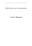
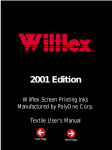
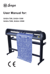
®
OPERATING GUIDE
for Secabo C60II and C120II
cutting plotters
Congratulations on purchasing your Secabo cutting plotter!
Please read this guide carefully. It tells you how to prepare your cutting plotter for production use in a
few easy steps.
This guide must not be reproduced in any form without written consent from Nepata Vertrieb GmbH.
Modifications and errors in technical specifications and product features reserved.
Nepata Vertrieb GmbH does not assume any liability for direct or indirect damage that occurs due to the
use of this product.
1
®
1. Precautions
Please read these instructions and precautionary notes carefully before using the machine for
the first time!
• Do not place magnetic objects near the cutting head as even contact pressure cannot otherwise be
guaranteed.
• Do not unplug the computer connection lead while a plot is running.
• Release the pressure on contact rollers when not in use by flipping the pressure levers up.
• Keep your hands out of the machine while it is connected to the mains power supply.
• Never open the machine case and do not attempt to modify the machine.
• Avoid liquid spills and metal objects entering the interior of the cutter.
• Make sure the power supply is grounded.
• Make sure the mains power supply (220V) does not fluctuate by more than ±10%. In case of
mains power fluctuations, use a voltage stabilizer.
• Unplug the power lead during longer periods of inactivity.
• Keep your hands well away from the knife holder while a cutting job is running!
• Always cancel the active job before adjusting the knife holder!
• Keep the cutting plotter well out of the reach of children, and never leave the machine or machine
parts unattended when connected to the mains.
• Never touch the tips of drag knives to avoid injury.
• Set up the machine on a stable base to avoid danger of falling.
• Never run the machine during a thunder storm; lighting could damage or destroy the machine.
2
®
2. What‘s in the box
Please check immediately to ensure that you have received the following articles:
• Cutting Plotter
• Cutting Plotter Stand (dismantled)
• Power Lead
• Knife Holder
• 3 Drag Knives
• USB connection lead
• Penholder and pens
• CD Rom with software, drivers and
Operating Guide
3. Setting up the Stand
a
Required tools: 1 x Phillips screwdriver, 2 x size 13
spanners
b
c
• Start by using the countersunk Phillips screws to
connect parts (a) and (b).
b
• Attach the two support plates (c) to the two upper
threaded bore holes (b) which are slightly displaced
outwards.
d
• Use Phillips screws to connect the strut (d) to the
central threaded bore holes.
• Turn the stand upside-down and use small Phillips
screws to connect (e) and (b).
e
• (Parts not shown in figure) Attach the roll holder to
the two support plates (c) using two dowel pins at both sides. To do so, attach the two dowel pins
on one side using the nuts provided. Then push both bars onto the dowel pins, and insert the dowel pins into the bars at the other end. Tighten the nuts provided to fix everything in place.
3
®
4. Description of Machine
a)
b)
c)
4.1. Front view
a) Case lid
b) Cutting head
c) Operating panel
d) Cut-off groove
d)
4.2. Rear view
e) Pressure rollers
4.3. Side views
e)
f)
f) USB port
g) Power supply, Fuse, Switch
g)
4.4. Operating panel
a) LCD display
b) Online/Offline key
c) Test key (knife test)
d) Pause key (to interrupt plot)
e) Mode key
f) arrow keys for moving the cutting head
and for loading/removing media
g) Zero Point key
h) Key for raising/lowering knives
i) +/- Key for mode settings
a)
c)
e)
b)
TEST
MODE
ON
OFF
LINE
PAUSE
f)
g)
h)
i)
+
4
d)
®
5. Installation and Test
5.1. Setting up the cutting plotter
Make sure that there is enough space to allow unhindered media input and output at the front
and rear of the cutting plotter. The operating environment for the cutting plotter must be clean
and dry.
• Attach the plotter to a 200V mains power supply using the supplied power lead.
• Now switch the cutting plotter on. Caution – when the cutting plotter is switched on the cutting
head automatically moves to the right.
5.2. Attaching a Secabo Cutting Plotter to a computer via the USB port
5.2.1. Installation virtual interface
Your Secabo Cutting Plotter has a USB interface which is used to connect the plotter to your PC.
Note that your Secabo Cutting Plotter is only supported by Windows 2000 and Windows XP. You
cannot use the cutting plotter with Windows 95 / 98 / Me.
To ensure that your Secabo Cutting Plotter also works with cutting/plotting programs that support serial
or parallel connections only, the machine has an internal USB RS232 adapter. This sets up a virtual serial
port on your PC; the port can be addressed as COM1 or COM2.
• When you connect your cutting plotter to your computer, Windows should display the new hardware component that it has detected. You can now select a source for the required device driver. To
do so, select the USB-Driver driver directory on the CD provided with your cutting plotter. Windows
will now install the USB driver as a new serial port.
• To discover the number that Windows has assigned to the port, you now need to launch the Windows Device Manager. To do so, right click the desktop and select Properties. A window appears.
Click on the Hardware tab and then select Device Manager. Below Ports, you will find a list of serial
and parallel ports for your computer, including the USB To Serial port. The port number indicated
for this interface (e.g. COM1) is the port number you need to configure (e.g. in Artcut).
• If you need to change the port number, proceed as follows: Right click the port entry and select
Properties. Now click on Advanced in the Port Settings tab and select a new COM Port Number.
This may be necessary, if you use a cutting/plotting program such as Artcut, as Artcut only supports
cutting plotters attached to ports COM1 or COM2.
5
®
5.2.2. Installing the plotter driver
To use the cutting plotter with CorelDraw or Freehand, you first need to install the plotter as a printer on
your computer system. The printer driver is located on the supplied CD. Simply run the driverSecabo.exe
file in the printer driver directory. To install the printer driver, you need to select the virtual interface you
installed previously.
After installing the printer driver, you can plot jobs directly from CorelDraw, Freehand or Adobe Illustrator
(Version 11 or newer) on your Secabo Cutting Plotter by selecting File - Print.
5.2.3. Using Artcut
Your Secabo Cutting Plotter includes Artcut cutting software. Please refer to the Artcut User Manual for
information on installing and using the software.
5.3. Fitting and adjusting knives
• Take one of the cutter knives provided, and insert it into the knife holder so that the blade protrudes
from the front.
• Now turn the black part at the front to set the cutting depth.
• The depth is set correctly when you feel a light scratching on carefully rubbing your fingertip over
the tip of the knife. As the knife depth setting depends on the media you will be cutting, you may
need to re-adjust later.
Knife setting correct
Knife setting too deep
Knife setting too shallow
• You can press the pin at the rear of the knife holder to remove and replace the blade you have
inserted at any time. Caution – danger of injury!
As various media thicknesses require different knife settings, or even special blades, you may
need to repeat the steps detailed above.
6
®
5.4. Inserting the knife holder
• Start by loosening the knife holder screw on the cutting head.
• Then holding the knife holder from the top, push the knife holder into the aperture at the side until
it is seated properly, and tighten the retaining screw.
5.5. Loading media
• Always load media for processing from the rear of the machine.
• Pull the media up to the cutting strip to set the zero point correctly. See Section 5.6 in this guide for
details of setting the zero point.
• If you are using roll media rather than precut media, use the supplied roll holder to ensure that the
media unrolls smoothly.
• When loading media, ensure that the media is straight to avoid warping when transporting the media. A misalignment of just a few millimeters can cause severe media warp in longer plots.
• You can load the media at any horizontal position in the machine; it does not matter whether the
media is centered, or aligned on the left or right.
• Fix the two pressure rollers by snapping them into place at the outer edges of the media; this ensures straight feeding of the media and defines the maximum cutting area.
• To make sure that the media is positioned correctly, fix one of the pressure rollers first. You can then
adjust the media slightly before fixing the second pressure roller to ensure straight feeding of the
media.
5.6. Setting the zero point
The zero point is the point on the loaded media where the plot job will start. You need to set
the zero point whenever you switch the machine on, or after loading media for processing.
• Switch the cutting plotter on. When the cutting plotter is switched on, the cutting head moves to
the right and stops. The zero point is now set to the machine‘s absolute zero point, but this can be
changed and modified as required.
• To change the zero point setting for your cutting plotter, first press the Online/Offline key to toggle
to Offline Mode.
• You can now adjust the zero point by pressing the four arrow keys. We recommend setting the zero
point to the front right corner of the media. While the cutter head is moving, the current coordi7
®
nates are display relative to the previous zero point setting.
• Press the key in the center of the arrow key block to confirm the new zero point setting. The coordinates shown in the display are set to zero.
By setting the zero point, you can also target specific media positions, or avoid damaged
areas of the media.
5.7. Settings Mode
You can press the Mode key multiple times in Offline mode to toggle through the following menus:
Press
Use the Up/Down keys to set the pressure in units of one gram; the valid range of values is between 70g
and 400g.
Recommended values for several media:
normal self-adhesive media:
approx. 100g
Transflex media:
approx. 100g
Neon foil:
approx. 110g
Flock foil:
approx. 120g
Laminated media:
approx. 180g-250g,
Sandblast foil:
approx. 300g-400g
When setting the cutting force, please note that the correct setting mainly depends on the knife
holder, the position of the knife, and the loaded media. These settings are subject to variation.
Speed
Again use the Up/Down keys on the operating panel to set the speed. In most cases, the maximum
speed of 40cm/sec. is recommended.
X-Scale/Y-Scale
Do not change the X and/or Y-Scale values as they are used to compensate for wear and tear of the
transport belts. Only change these settings, if plots become distorted.
Baud
The baud rate is the communication speed for the cutting plotter and the serial port on your computer.
This setting must reflect the baud rate set in the properties dialog for your COM port, or in the Artcut
software. A value of 9600 is typically set, but this can vary depending on your COM port setting.
Additional settings in the display:
Pause (pause the plot)
Press this key to pause the current plot; you can then modify settings performed previously. The display
now shows the pressure (P=Pressure) and the speed (S=Speed); both values can be modified by pressing the Up/Down and/or +/- keys on the operating panel
8
®
5.8. Cutting test
• Press the Text key twice to perform a cutting test. The cutting plotter will now cut a square containing a circle divided into four quadrants.
• The cutting test helps you verify the knife holder setting and cutting force. The cutting test should
give you clean and straight cuts in the loaded media; there should be no damage to the backing.
• If the test cuts through the backing, either the cutting force is too high, or the blade or knife holder
setting is incorrect. Change these settings and repeat the cutting test.
• You will also need to change the settings, in case of imprecise or too shallow cuts.
6. After cutting
9
®
6.1. Removing the media
• After pressing the Online key in the operating panel, you can use the arrow keys to feed the media forward and backward. To ensure clean cutting of the plotted objects, feed the media forward
sufficiently to allow a clean cut at the cutting edge using a suitable knife.
• If you are working with pre-cut media, simply release the pressure rollers and remove the media
from the machine.
6.2. Finishing the media
6.2.1. Weeding
Weeding refers to the process of removing the parts of the
media you do not require. We recommend using a scalpel or a
special weeding tool for this job, to avoid damage to the adhesive surface.
After weeding, you can use a transfer press to transfer flock and
flex media to the textiles to be processed; apply application tape
to self-adhesive media before transferring.
6.2.2. Applying
Apply application tape to the weeded material and use a roller
or flat scraper to press down firmly. To apply adhesive to the
transfer foil, remove the backing from the foil to leave the adhesive affixed to the application tape. You can now apply the
adhesive to the required surface.
7. Drag knives
10
®
Drag knives are extremely sensitive, but also extremely sharp and dangerous precision tools.
• Always keep knives well out the reach of children!
• To avoid danger of injury, always handle knives with caution.
• Handle drag knives with caution, and always replace the protective cap when not in use. If the tip
of the knife comes into contact with a hard material such as glass or stone, tiny fissures may occur
at the knife tip making the knife useless. Note the following to avoid unnecessary wear and tear of
your drag knives and to ensure maximum working life.
• Avoid cutting the backing of loaded media. The deeper you cut into the loaded material, the more
wear and tear the drag knives are exposed to.
• Always set the cutting depth of the knives to cut the media precisely and cleanly without cutting too
deep. Extending the knives beyond the required cutting depth impacts the service life of the knives
without achieving better cutting results.
• Always use the right custom knives for thicker material (e.g. use flock knives for flock media).
• Ragged edges on cutting the loaded media show that the knives are blunt. Always replace blunt
knives immediately!
8. Technical Specifications Secabo C60II and C120II
11
®
max. media width
max. cutting width
max. speed
Mechanical resolution
Cutting force
Accuracy
Connectors
Drive
Power consumption
Ambient temperature
Dimensions
Weight
C60II
730mm
630mm
400mm/s
0,0254mm
0-400g
+/- 0,1mm
USB
DC Micro Stepper
< 120W
+5°C - +35°C
101 x 23 x 28cm
22kg
C120II
1300mm
1205mm
400mm/s
0,0254mm
0-400g
+/- 0,1mm
USB
DC Micro Stepper
< 120W
+5°C - +35°C
161 x 23 x 28cm
32kg
Nepata Vertrieb GmbH
www.secabo.com
Raiffeisenstr. 15a
85276 Pfaffenhofen a.d. Ilm
Germany
12