1
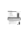
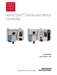
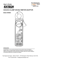
User’s Guide
600A AC Clamp Meter
Model 38387
99 Washington Street
Melrose, MA 02176
Phone 781-665-1400
Toll Free 1-800-517-8431
Visit us at www.TestEquipmentDepot.com
Back to the Extech 38387 Product Info Page
Safety
International Safety Symbols
This symbol, adjacent to another symbol or terminal,
indicates the user must refer to the manual for further
information.
This symbol, adjacent to a terminal, indicates that, under
normal use, hazardous voltages may be present
Double insulation
A UL mark does not indicate that this product has been evaluated for
the accuracy of its readings.
SAFETY NOTES
•
Do not exceed the maximum allowable input range of any function
•
Do not apply voltage to meter when resistance function is selected.
•
Set the function switch OFF when the meter is not in use.
•
Remove the battery if meter is to be stored for longer than 60 days.
WARNINGS
•
Set function switch to the appropriate position before measuring.
•
When measuring volts do not switch to current/resistance modes.
•
Do not measure current on a circuit whose voltage exceeds 240V.
•
When changing ranges using the selector switch always disconnect
the test leads from the circuit under test.
•
Do not exceed the maximum rated input limits.
2
CAUTIONS
•
Improper use of this meter can cause damage, shock, injury or
death. Read and understand this user manual before operating the
meter.
•
Always remove the test leads before replacing the battery or fuses.
•
Inspect the condition of the test leads and the meter itself for any
damage before operating the meter. Repair or replace any damage
before use.
•
Use great care when making measurements if the voltages are
greater than 25VAC rms or 35VDC. These voltages are considered
a shock hazard.
•
Remove the battery if the meter is to be stored for long periods.
•
Always discharge capacitors and remove power from the device
under test before performing Diode, Resistance or Continuity tests.
•
Voltage checks on electrical outlets can be difficult and misleading
because of the uncertainty of connection to the recessed electrical
contacts. Other means should be used to ensure that the terminals
are not "live".
•
If the equipment is used in a manner not specified by the
manufacturer, the protection provided by the equipment may be
impaired.
3
Specifications
Function
AC Current
AC Voltage
DC Voltage
Resistance
Range and Resolution
199.9 ACA
600 ACA
600 VAC
600 VDC
1999 Ω
Accuracy (of reading)
± (1.5% + 4 digits)
@ 50/60Hz
± (1.0% + 1 digits)
± (1.0% + 2 digits)
Jaw size
Opening 1.3" (33mm) approx.
Display
Continuity
3-1/2 digits (2000 counts) LCD
Audible tone < 40Ω approx.
AC bandwidth
Safety compliance
40Hz to 400Hz
IEC 1010-1 and VDE 0411
Operating Temperature
32 to 122 F (0 to 50 C)
Storage Temperature
-4 to 140 F (-20 to 60 C)
o
o
o
o
Over voltage
Cat II 600V
Overload protection
250V AC/DC Spark Gap protection;
PTC protection for Ω range to 250V
Battery
9V battery (IEC 6F22)
Auto Power OFF
After 10 minutes of inactivity
Dimensions/Weight
8x3.2x1.7" (204x80x43mm)/0.62 lbs. (281g)
Safety
For indoor use and in accordance with
Overvoltage Category II, Pollution Degree 2.
Category II includes local level, appliance,
portable equipment, etc., with transient
overvoltages less than Overvoltage Cat. III.
4
Meter Description
1.
Transformer jaws
2.
Data Hold button
3.
Peak Hold button
4.
LCD Display
5.
COM Input Terminal
6.
Jaw opening trigger
7.
Function select switch
8.
Voltage, Resistance Input Terminal
Operation
NOTICES: Read and understand all warning and precaution
statements listed in the safety section of this operation manual prior to
using this meter. Set the function select switch to the OFF position
when the meter is not in use.
AC/DC Voltage Measurements
1. Insert the black test lead into the negative COM terminal and the
red test lead into the positive V terminal.
2.
Set the function switch to the AC or DC voltage
range position (ACV or DCV).
3.
Connect the test leads in parallel to the circuit
under test.
4.
Read the voltage measurement on the LCD
display.
5
AC Current Measurements
WARNING: Ensure that the test leads are
disconnected from the meter before making current
clamp measurements.
1. Set the Function switch to the 600 or 200A range.
If the range of the measured is not known, select
the higher range first then move to the lower
range if necessary.
2. Press the trigger to open jaw. Fully enclose one
conductor to be measured.
3. The clamp meter LCD will display the reading.
Resistance and Continuity Measurements
1. Insert the black test lead into the negative COM terminal and the
red test lead into the Ω terminal.
2. Set the function switch to the Ω •))) position.
3. Touch the test probe tips across the circuit or component under
test. It is best to disconnect one side of the device under test so the
rest of the circuit will not interfere with the resistance reading.
4. For Resistance tests, read the resistance on the LCD display.
5. For Continuity tests, if the resistance is < 40Ω, a tone will sound.
Data Hold
To freeze the LCD meter reading, press the data hold button. The data
hold button is located on the left side of the meter (top button). While
data hold is active, the DH display icon appears on the LCD. Press the
data hold button again to return to normal operation.
Peak Hold
To hold the highest reading on the LCD, press the peak hold button. The
peak hold button is located on the left side of the meter (bottom button).
The meter reading will not change as readings change, rather it will only
display the highest reading encountered since the peak hold button was
pressed. Press the peak hold button again to return to normal operation.
6
Maintenance
WARNING: To avoid electrical shock, disconnect the meter from any
circuit, remove the test leads from the input terminals and turn OFF the
meter before opening the case. Do not operate with open case.
Cleaning and Storage
Periodically wipe the case with a damp cloth and mild detergent; do not
use abrasives or solvents. If the meter is not to be used for periods of
longer than 60 days, remove the battery and store it separately
Battery Replacement
1. Remove the three rear Phillips head screws
2.
Open the battery compartment
3.
Replace the 9V battery
4.
Re-assemble the meter
99 Washington Street
Melrose, MA 02176
Phone 781-665-1400
Toll Free 1-800-517-8431
Visit us at www.TestEquipmentDepot.com
Back to the Extech 38387 Product Info Page
7