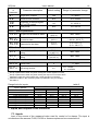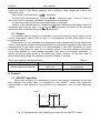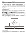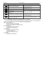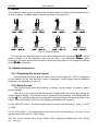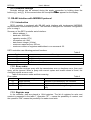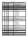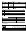
1
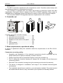
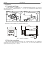
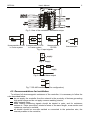
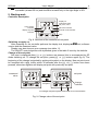
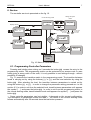
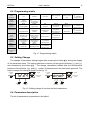
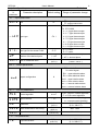
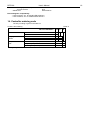
TEMPERATURE CONTROLLER
48 x 48 mm
RE70 TYPE
USER’S MANUAL
1
RE70-09
User's Manual
2
Contents:
1. Application ........................................................................................................................ 3
2. Controller set .................................................................................................................... 3
3. Basic requirements, operational safety.......................................................................... 3
4. Installation......................................................................................................................... 4
4.1. Controller installation ................................................................................................... 4
4.2. Electrical connections.................................................................................................. 4
4.3. Recommendations for installation ............................................................................... 5
5. Starting work..................................................................................................................... 6
6. Service ............................................................................................................................... 7
6.1. Programming Controller Parameters ........................................................................... 7
6.2. Programming matrix .................................................................................................... 8
6.3. Setting Change............................................................................................................ 8
6.4. Parameters description ............................................................................................... 8
7. Inputs and outputs of the controller ............................................................................. 10
7.1. Inputs ........................................................................................................................ 10
7.1. Output ....................................................................................................................... 11
8. Control ............................................................................................................................. 11
7.1. ON-OFF algorithm ..................................................................................................... 11
7.2. Innovative SMART PID algorithm .............................................................................. 12
9. Alarms ............................................................................................................................. 14
10. Additional functions ..................................................................................................... 14
10.1. Displaying the control signal .................................................................................... 14
10.2. Manual mode........................................................................................................... 14
10.3. Defaults Settings ..................................................................................................... 15
11. RS-485 interface with MODBUS protocol ................................................................... 15
11.1. Introduction.............................................................................................................. 15
11.2. Error codes .............................................................................................................. 15
11.3. Register map ........................................................................................................... 15
12. Error signaling .............................................................................................................. 17
13. Technical data............................................................................................................... 18
14. Controller ordering code.............................................................................................. 19
RE70-09
User's Manual
3
1. Application
The RE70 controller is destined for the temperature control. Controller works directly with
the resistance sensors or thermoelectric sensors.
The controller is equipped with one output that allows for dual-point control and alert
signalization. Dual-point control is based on the PID or ON/OFF algorithm. Relay output is
equipped with a switchable contact and allows for indirect control of the low-power objects.
The innovative SMART PID algorithm has been implemented in the controller.
2. Controller set
2
1
3
4
12 34
OU T SP
ST
RE 70
5
Complete set of the controller includes:
1. controller ................................................ 1 pc
2. plug with 6 screw terminals .................... 1 pc
3. plug with 8 screw terminals .................... 1 pc
4. holders to fix the meter in the panel ....... 4 pcs
5. seal ........................................................ 1 pc
6. user’s manual ........................................ 1 pc
7. guarantee card....................................... 1 pc
3. Basic requirements, operational safety
In terms of operational safety the controller meets the requirements of the EN 61010-1
standard.
Comments concerning safety:
• Assembly and installation of the electrical connections should conducted only by
people authorised to perform assembly of electric devices.
•
Always check the state of connections before turning the controller on.
•
Prior to taking the controller housing off, always turn the supply off and disconnect
measuring circuits.
•
Removal of the controller housing during the warranty period voids the warranty.
•
The device is designed to installation and usage in the industrial electromagnetic
environment.
•
The installation should have a switch or a circuit-breaker installed. This switch should
be located near the device, easy accessible by the operator and suitably marked.
RE70-09
User's Manual
4
4. Installation
4.1. Controller installation
Fix the controller to the board with four screw brackets as shown in the fig. 1. A slot in
the panel must have the dimensions 45+0,6 x 45+0,6 mm. The thickness of the panel material
cannot exceed 15 mm.
1
2
Fig. 1. Controller installation.
Dimensions of the controller are presented on the fig. 2.
max. 93
8
70
48
48
max.15
Fig. 2. Controller dimensions.
4.2. Electrical connections
The controller has two separate connectors with screw terminals. One strip enables the
connection of the supply and outputs by a wire of 2,5 mm2, the second strip enables input
signal connections by a wire of 1,5 mm2.
RE70-09
User's Manual
5
Fig. 3. View of the controller's connection strips.
Pt1000
5
4
3
thermoresistor Pt100 thermoresistor Pt100
thermoresistor
in 2-wire system
in 3-wire system
Pt1000
Fig. 4. Input signals
13
14
+
Pt100
5
4
3
-
Pt100
5
4
3
2
1
thermocouple
supply
Fig. 5. Supply
9
10
11
load
supply
Fig. 6. Control/Alarm output
B (-)
8
A(+) 7
Fig. 7. RS-485 interface (only for configuration)
4.3. Recommendations for installation
To achieve full electromagnetic resistance of the controller, it is necessary to follow the
rules described below:
do not supply the controller from the network in the proximity of devices generating
high pulse noises and do not apply common earthing circuits,
apply network filters,
wires leading measuring signals should be twisted in pairs, and for resistance
sensors in 3-wire connection, twisted of wires of the same length, cross-section and
resistance, and led in a shield,
all shields should be one-side earthed or connected to the protection wire, the
nearest possible to the controller,
RE70-09
User's Manual
6
as a rule of thumb, wires transmitting different signals should be spaced as far as it
is possible (at least 30 cm) and should be crossed only at the right angle of 90°.
5. Starting work
Controller description
display for
measured value,
set point, menu
active output
indicator
self-tune indicator
manual mode indicator
display set point
indicator
keys
Fig. 8. Overview of the controller's front panel.
Switching a supply on
After powering on, the controller performs the display test, displays r e 7 0 text, software
version and the measured value.
Display may also show an error message (see table 11).
The ON-OFF control algorithm with hysteresis given in the table 2 is set by the defaults.
Change of the set point
Set point is displayed after ? or > buttons are pressed, this is accompanied by SP
diode switching on. To change the set point, press ? or > buttons again (fig. 9). The
beginning of the change is signaled by pulsing dot symbol on the display. New set point must
be accepted with a @ button within 30 seconds after the ? or > button have been
pressed, otherwise regulator will display set point with previously set point.
measured
value
or
accept new
set-point
set-point
change
indicator
to change set-point press and hold one of the button
Fig. 9. Change value of the set point.
RE70-09
User's Manual
7
6. Service
The controller service is presented on the fig. 10.
change set point
mode
normal working mode
to change press
or
measured
value
display control
signal
set point
to accept press
to cancel press
+
h___
2sec.
+
manual
mode
2 sec.
+
active
access code
tune
press and hold
to decrease
the value
self-tune mode
press and hold
to increase
the value
code
Y
N
2sec.
Y
correct
code?
locking of change
N
err
3sec.
+
parameter
programming
mode
Fig. 10. Menu of controller service
6.1. Programming Controller Parameters
Pressing and holding down during ca 2 seconds the button @ causes the entry to the
programming matrix. The programming matrix can be protected by an access code. In case
when giving a wrong value of the code, it is only possible to see settings through - without
possibility of changes.
Fig. 11 presents the transition matrix in the programming mode. The transition between
levels is carrying out by using the buttons ? or > and the level selection by using the
button @ . After selecting the level, the transition between parameters is carried out by
using the buttons ? or > . In order to change the parameter setting proceed acc. to the
section 6.3. In order to exit from the selected level, transit between parameters until appears
the symbol [. . .] and press the button @ . In order to exit from the programming matrix to
the normal working mode, transit between levels until appears the symbol [. . .] and press the
button @ .
Some controller parameters can be invisible – it depends on the current configuration.
The description of parameters shows the table 1. The return to the normal working mode
follows automatically after 30 seconds since the last button pressure.
RE70-09
User's Manual
8
6.2. Programming matrix
inp
unit
Input
parameters
iNty
Unit
Input type
outp
out
...
Output
parameters
Output
configuration
Transition to
the higher level
ctrl
alg
type
sHif
dp
...
Type of line
Shift of measured
value
Position of decimal
point
Transition to
the higher level
Hy
sTlo
sTHi
...
Type of control
Hysteresis
Lower threshold for
self-tuning
Upper threshold for
self-tuning
Transition to
the higher level
ti
td
y0
to
...
Integral time
constant
Derivative time
constant
Correction of
control signal, for P
or PD control
Pulse period
Transition to
the higher level
aLsp
aLdu
aLHy
...
Set point for the
absolute alarm
Deviation from the
set point of the
relative alarm
Alarm hysteresis
Transition to
the higher level
Control
parameters
Control algorithm
pid
pb
PID Parameters
Proportional band
alar
Alarms
parameters
t-li
spp
spl
spH
...
Set point
parameters
lower limitation of
the set point
setting
upper limitation of
the set point
setting
Transition to
the higher level
seru
seCU
sTfn
...
Service
parameters
Access code
Self-tuning function
Transition to
the higher level
...
Exit from the
menu
Fig. 11. Programming matrix
6.3. Setting Change
The change of parameter setting begins after pressing the button @ during the display
of the parameter name. The setting selection is carried out through the buttons ? and >
and accepted by the button @ . The change cancellation follows after the simultaneous
pressure of the buttons ? and > or after 30 seconds since the last button pressure. The
way to change the setting is shown on the fig. 12.
+
to change
press
1234
decrement
value
+
cancel
to change
press
accept new
value
increment
value
oNof
previous
text value
next text
value
Fig. 12. Setting change of number and text parameters.
6.4. Parameters description
The list of parameters is presented in the table 1.
cancel
accept new
value
RE70-09
User's Manual
9
List of configuration parameters
Symbol
of
parameter
Parameter description
Table 1
Default setting
Range of parameter change
i n p – Input parameters
unit
Unit
qC
q C : degrees Celsius
q f : degrees Fahrenheit
p t 1: Pt100
p t 1 0: Pt1000
t - ,: J type thermocouple
iNty
t - t: T type thermocouple
Input type
pt1
t - k: K type thermocouple
t - s: S type thermocouple
t - r: R type thermocouple
t - b: B type thermocouple
t - n: N type thermocouple
t-li
Line type for the sensor Pt100
dp
Position of the decimal point
1-dp
shif
Shift of measured value
0.0 °C
(0.0 °F)
2-p
2 - p: 2-wire
3 - p: 3-wire
0 _ d p: without a decimal place
1 _ d p: 1 decimal place
-100.0…100.0 °C
(-180.0…180.0 )
o u t p – Output parameters
o f f: control off
Y: control signal
A H i: upper absolute alarm
out
Output configuration
y
A l o: lower absolute alarm
d w H i: upper relative alarm
d w l o: lower relative alarm
d w i n: internal relative alarm
d w o u: external relative alarm
c t r l – Control parameters 1)
alg
Control algorithm
type
Type of control
Hy
Hysteresis 4)
sTlo
sTHi
Lower threshold for self-tuning
Upper threshold for self-tuning
oNof
inu
2.0 °C
(3.6 °F)
0.0 °C
(32.0 °F)
800.0 °C
(1,472.0 °F)
o N o f: ON-OFF control algorithm
p i d: PID control algorithm
d i r: direct control (cooling)
i n u: reverse control (heating)
0.2…100.0 °C
(0.2…180.0 °F)
MIN…MAX
6)
MIN…MAX
6)
p i d – PID parameters 2)
pb
Proportional band
30.0 °C
(540.0 °F)
0.1…550.0 °C
(0.1…990.0 °F)
RE70-09
User's Manual
Symbol
of
parameter
ti
td
y0
to
Parameter description
10
Default setting
Range of parameter change
Integral time constant
300
0…9999 s
Derivative time constant
60.0
0.0…2500 s
Correction of control signal,
for P or PD control
0.0
0…100.0 %
Pulse period
20.0
0.5…99.9 s
a l a r – Alarms parameters 3)
aLsp
Set point for the absolute alarm
aLdu
Deviation from the set point of
the relative alarm
aLHy
Hysteresis for the alarm
0.0 °C
(32.0 °F)
0.0 °C
(0.0 °F)
MIN…MAX
6)
-200,0… 200,0 °C
(-360.0…360.0 °F)
0.2…100.0 °C
(0.2…180.0 °F)
2.0 °C
(3.6 °F)
s p p – Set point parameters
spl
spH
Lower limitation of the set point
setting
Upper limitation of the set point
setting
-200.0 °C
(-3,280.0 °F)
1,767.0 °C
(3,212.6 °F)
MIN…MAX
6)
MIN…MAX
6)
s e r p – Service parameters
seCU
sTfn
Access code
5)
0
on
Self-tuning function
0…9999
o f f: locked
o n: available
1)
Group of parameters visible only when setting the output on the control signal.
Group of parameters visible only when setting the control algorithm on PID.
3)
Group of parameters visible only when setting the output on one of the alarm.
4)
Parameter visible only when setting the control algorithm on ON-OFF.
5)
Parameter hidden in the monitoring mode of parameters only for readout.
6)
See table 2.
2)
Range limits for inputs
Input / sensor
Thermoresistor Pt100
Thermoresistor Pt1000
J type thermocouple
T type thermocouple
K type thermocouple
S type thermocouple
R type thermocouple
B type thermocouple
N type thermocouple
table 2
MIN
°C
-200 °C
-200 °C
-50 °C
-50 °C
-50 °C
0 °C
0 °C
0 °C
-50 °C
MAX
°F
-328 °F
-328 °F
-58 °F
-58 °F
-58 °F
32 °F
32 °F
32 °F
-58 °F
°C
850 °C
850 °C
1,200 °C
400 °C
1,372 °C
1,767 °C
1,767 °C
1,767 °C
1,300 °C
°F
1,562 °F
1,562 °F
2,192 °F
752 °F
2,501.6 °F
3,212.6 °F
3,212.6 °F
3,212.6 °F
2,372 °F
7. Inputs and outputs of the controller
7.1. Inputs
Input is the source of the measured value used for control or for alarms. The input is
universal and the sensors Pt100, Pt1000 or thermocouples can be connected to it.
RE70-09
User's Manual
11
Start by using a u n i t parameter to set the temperature display unit. Unit change
resets the value to the factory settings, with a different value ranges for Celsius and
Fahrenheit scale.
Input signal is selected with a i N t y parameter.
For the Pt100 thermoresistor, choose the t - l i connection type - 2-wire or 3-wire. In
the 3-wire Pt100 connection, resistance compensation is automatic.
For thermocouples, a cold terminal compensation is automatic.
Position of the decimal point is a additional parameter that determines display format of
measured value and set point; it is set by the d p parameter. Correction of the indicated
measured value is determined by the s h i f parameter.
7.1. Output
The controller has one output. It is possible to choose the following output options: on-off
control, proportional control (PID) or alert. It is necessary to set the pulse period for the
proportional control.
Pulse period is a time between two subsequent input engagements during proportional
control. Pulse period length should be adjusted for the dynamic properties of the object and
characteristics of the output device. It is recommended to use SSR transmitter for quick
processes. Relay output is used for a contactor control in the slow-changing processes.
Long pulse periods for quick-change processes may cause unnecessary oscillation. In
theory, the shorter pulse period is, the better the control, however for the relay output a
period should be as large, as possible to optimize lifespan of the relay.
Pulse period setting recommendations
Output
Pulse period is
recommended >20s
min. 10 s
electromagnetic transmitter
min. 5 s
Table 3
Load
5 A/230 VAC
or a contactor
2 A/230 VAC
8. Control
7.1. ON-OFF algorithm
When high accuracy of a temperature control is not required, especially for the high
time constant and small delay, it is possible to use ON-OFF control with hysteresis.
Disadvantage of this method is the occurrence of oscillations, even at small hysteresis
values.
output
hysteresis
on
off
setpoint
value
measured
value
Fig. 13. Operation way of the heating type output for the ON-OFF control.
RE70-09
User's Manual
12
7.2. Innovative SMART PID algorithm
When high precision of the temperature control is necessary, it is recommended to use
PID algorithm. Innovative SMART PID algorithm ensures increased precision in the
extended range of the control object classes.
Tuning of the controller to object is achieved by automatically selected PID parameters
using the self-tuning function or manual setting the value of the proportional element, integral
element and derivative element.
7.2.1. Self-tuning
The controller has the function to select PID settings. In most cases these settings
ensure an optimal control.
To begin the self-tuning, transit to the t u n e message (acc. to the fig. 10) and hold down
the button @ during at least 2 sec. If the control algorithm is set on ON-OFF or the selftuning function is locked, then the tune message t u n e is hidden.
For a correct realization of the self-tuning function, it is required to set the parameters
s T l o and s T H i . The parameter s T l o should be set on the value corresponding to the
measured value at the switched off control. For object temperature control, you can set 0ºC.
The parameter s T H i should be set on the value corresponding to the maximum measured
value when the control is switched on the full power.
The flickering AT symbol informs about the activity of the self-tuning function. The
duration of self-tuning depends on dynamic object properties and can last maximally 10
hours. During self-tuning or directly after it, over-regulations can occur and because of this,
one must set a smaller set point if possible.
The self-tuning is composed of following stages:
self-tuning process
YES
- calculation of PID settings and stored
them in the non-volatile memory
- start control with new PID settings
self-tuning
ended
with success
NO
- enter to manual mode
- the error code is on the display until
confirmation
The self-tuning process will be stopped without counting PID settings, if a supply
decay occurs or the button @ will be pressed. In this case, the control with current PID
settings will be started.
If the self-tuning experiment does not end with success, then an error code will be displayed,
acc. to the table 4.
RE70-09
User's Manual
Error codes for self-tuning function
Error code
Reason
eS0 1
P or PD control was selected.
eS0 2
The set point is incorrect.
eS0 3
The button @ was pressed.
The maximal self-tuning duration time has
been exceeded.
The waiting time of switching has been
exceeded.
eS0 4
eS0 5
13
Table 4
Procedure
One must choose PI, PID control, i.e. the TI unit
must be higher than zero.
Change temperature set point or the
parameters sTlo, sT Hi.
Check, if the temperature sensor is correctly
situated, if the set point value is not set too
higher for the given object.
eS0 6
The input range limit has been exceeded.
Take note of the way to connect the sensor. Do
not allow that the overflow results in exceeding
of the input range limit.
eS2 0
Very non-linear object, enabling to obtain
correct values of PID parameters, or an
interference has occurred.
Carry out the self-tuning again. If that does not
help, choose PID parameters manually.
7.2.2. Proceeding in case of a unsatisfactory PID control
It is recommended to choose PID parameters, changing the value in a twice higher or
twice less. During the change, one must respect following principles.
a) Free jump response:
− decrease the proportional band,
− decrease the integral and derivative time.
b) Over-regulations
− increase the proportional band,
− increase the derivative time,
c) Oscillations
− increase the proportional band,
− increase integral time,
− decrease the derivative time,
d) Instability
− increase the integral time.
RE70-09
User's Manual
14
9. Alarms
The controller output can be configured as an alarm output. For this, set the parameter ou t
as one of alarms. Available types of alarms are given on the figure 14.
aLsp
aLsp
absolute high
absolute lower
(o
out = AHi)
(o
out = Alo)
a L d u (+)
SP
SP
a L d u (-)
relative high
relative high
(o
out = dwHi)
(o
out = dwHi)
aLdu
SP
SP
a L d u (-)
relative lower
(o
out = dwlo)
a L d u (+)
relative lower
aLdu
SP
SP
aLdu
relative internal
(o
out = dwlo)
(o
out = dwin)
Fig.14. Types of alarms
aLdu
relative external
(o
out = dwou)
The set point for absolute alarms is the value defined by the parameter a L s p , and for
relative alarms, it is the deviation from the set point - the parameter a L d u . Alarm
hysteresis, the zone around the set point in which the input state is not changed is defined
by the a L H y parameter.
10. Additional functions
10.1. Displaying the control signal
After pressing the button @ the value of the control signal (0…100%) is displayed
on the display. On the first digit the h mark is displayed. Control signal can be displayed
when the ou t parameter is set on y .
10.2. Manual mode
The manual mode gives the possibility to identify, test the object, or control it after a
sensor damage.
The entry to the manual mode follows after holding down the button @ during the
control signal is display. The manual mode is signaled by the pulsation of the diode with the
symbol . The controller interrupts the automatic control and begins the manual mode of the
output. The control signal value is on the display, preceded by the symbol h.
For the ON-OFF control – the control signal can be set up by the buttons ?
or 100%.
For the PID control – the control signal can be set up by the buttons ?
optional value from the 0.0…100% range.
and >
and >
at 0%
at any
The exit to the normal work mode follows after pressing simultaneously the buttons
?
and > .
RE70-09
User's Manual
15
10.3. Defaults Settings
Defaults settings can be restored during the supply connection by holding down the
buttons ? and > till the moment when the inscription f a b r appears on the display.
11. RS-485 interface with MODBUS protocol
11.1. Introduction
RE70 controller is equipped with RS-485 serial interface with implemented MODBUS
asynchronous communication protocol. The interface is designed for controller configuration
prior to using it.
Summary of the RE70 controller serial interface:
− device address: 1,
− baud rate: 9600 bit/s,
− operation modes: RTU,
− information unit: 8N2,
− data format: integer (16 bits)
− maximum response time: 500 ms,
− maximum number of registers read/written in one command: 32.
RE70 controller uses following protocol functions:
Table 5
Code
03
06
16
17
Meaning
n-registers read
1 register write
n-registers write
slave device identification
11.2. Error codes
If the controller receives query with the transmission error or checksum error, then such
query will be ignored. When a query with correct syntax and invalid values is found, the
controller returns an error code.
Table 6 shows error codes and their meaning.
Error codes
Table 6
code
meaning
reason
01
illegal function
function is not handled by the controller
02
illegal data address
register address out of range
03
illegal data value
register value out of range or register is readout
only
11.3. Register map
In the controller, data are placed in 16-bit registers. The list of registers for write and
readout is presented in the table 7. Operation "R-" – means the possibility of readout, and
the operation "RW" means the possibility for readout and write.
RE70-09
User's Manual
16
Map of the registers from address 4000
register
address
operati
marking
on
Table 7
parameter range
4000
-W
1
4001
4002
4003
4004
4005
4006
4007
4008
RRRRRRRR-
100…999
1301…9999
1…9999
0…0xFFFF
0…0xFFFF
acc. to the table 10
acc. to the table 10
0…1000
4009
UNIT
RW
0…1
4010
INPT
RW
0…8
4011
T-LI
RW
0…1
4012
DP
RW
0…1
4013
SHIF
RW
-1000…1000 [x10 °C]
-1800…1800 [x10 °F]
4014
OUT
RW
0…7
4015
ALG
RW
0…1
4016
TYPE
RW
0…1
4017
HY
RW
4018
4019
STLO
STHI
RW
RW
4020
PB
RW
4021
4022
TI
TD
RW
RW
2…1000 [x10 °C]
2…1800 [x10 °F]
acc. to the table 10
acc. to the table 10
1…5500 [x10 °C]
1…9900 [x10 °F]
0…9999
0…25000
4023
Y0
RW
0…1000
4024
4025
TO
ALSP
RW
RW
5…999
acc. to the table 10
description
Command register
1 – revert to defaults settings (except for interface
settings and defined programs)
Program version number [x100]
Older 4 digits of the serial number
Younger 4 digits of the serial number
Controller status – description in the table 8
Error status – description in the table 9
Measured value PV
Current set point SP
Control signal [% x10]
Unit
0 – degrees Celsius
1 – degrees Fahrenheit
Type of main input:
0 – thermoresistor Pt100
1 – thermoresistor Pt1000
2 – J type thermocouple
3 – T type thermocouple
4 – K type thermocouple
5 – S type thermocouple
6 – R type thermocouple
7 – B type thermocouple
8 – N type thermocouple
Type of line
0 – 2-wire
1 – 3-wire
Position of the decimal point of the main input
0 – without a decimal place
1 – 1 decimal place
Shift of the measured value of the main input
Output function
0 – no function
1 – control signal
2 – upper absolute alarm
3 – lower absolute alarm
4 – upper relative alarm
5 – lower relative alarm
6 – internal relative alarm
7 – external relative alarm
Control algorithm
0 – ON-OFF
1 – PID
Type of control
0 – direct control – cooling
1 – reverse control – heating
Hysteresis HY
Lower threshold for self-tuning
Upper threshold for self-tuning
Proportional band PB
Integral time constant TI [s]
Derivative time constant TD [s x10]
Correction of control signal Y0 (for P or PD control)
[% x10]
Pulse period of output [s x10]
Set point for the absolute alarm [x10]
RE70-09
User's Manual
register
address
marking
operati
on
4026
ALDV
RW
4027
ALHY
RW
4028
4029
4030
SPL
SPH
SECU
RW
RW
RW
2…1000 [x10 °C]
2…1800 [x10 °F]
acc. to the table 10
acc. to the table 10
0…9999
4031
STFN
RW
0…1
17
parameter range
description
-1800…1800 [x10 °C]
-3600…3600 [x10 °F]
Deviation from the set point of the relative alarm
Hysteresis for the alarm
Lower limitation of the fast set point change
Upper limitation of the fast set point change
Access code to the menu
Self-tuning function
0 – locked
1 – unlocked
Register 4002 – controller status
bit
0-11
12
13
14
15
Table 8
description
Reserved
Automatic/Manual mode: 0 – automatic, 1 – manual
State of alarm: 0 – active, 1 – inactive
Measured value beyond the range limits
Controller error – check the error register
Register 4003 – error register
bit
0-14
15
Table 9
description
Reserved
Input discalibrated
Input range limits
sensor type
Pt100
Pt1000
Fe-CuNi (J)
Cu-CuNi (T)
NiCr-NiAl (K)
PtRh10-Pt (S)
PtRh13-Pt (R)
PtRh30-PtRh6 (B)
NiCrSi-NiSi (N)
Table 10
range
UNIT = °C [x10]
UNIT = °F [x10]
-2000…8500
-2000…
…8500
-500…
…12000
-500…
…4000
-500…
…13720
0…
…17670
0…
…17670
0…
…17670
-500…
…13000
-3280…
…15620
-3280…
…15620
-580…
…21920
-580…
…7520
-580…
…25016
320…
…32126
320…
…32126
320…
…32126
-580…
…23720
12. Error signaling
Character messages signaling the incorrect controller operation.
Error code
Reason
Procedure
Table 11
_ _ __
Down overflow of the range
limit or lack of RTD
Check, if input signal values are situated in the appropriate
range – if yes, check if check if there is no short circuit in the
thermoresistor or the thermocouple is connected inversely.
: : ::
Upper overflow of the range
limit or break in the sensor
circuit
Check, if input signal values are situated in the appropriate
range – if yes, check if there is no break in the sensor circuit.
e R ad
Input discalibrated
e R ee
Configuration parameters
checksum error
Connect the controller supply again and if that is not effective,
contact the nearest service shop.
Connect the controller supply again and if that is not effective,
contact the nearest service shop.
RE70-09
User's Manual
18
13. Technical data
Input signals acc. to the table 12
Input signals and range limits for inputs
Sensor type
1)
*)
Table 12
Standard
Designation
Pt100
EN 60751+A2:1997
Pt100
Pt1000
EN 60751+A2:1997
Pt1000
Fe-CuNi
EN 60584-1:1997
J
Cu-CuNi
EN 60584-1:1997
T
NiCr-NiAl
EN 60584-1:1997
K
PtRh10-Pt
EN 60584-1:1997
S
PtRh13-Pt
EN 60584-1:1997
R
PtRh30-PtRh6
EN 60584-1:1997
B
NiCrSi-NiSi
EN 60584-1:1997
N
Range
-200…850 °C
-328…1,562 °F
-50…1200 °C
-58…2,192 °F
-200…850 °C
-328…1,562 °F
-50…400 °C
-58…752 °F
-50…1372 °C
-58…2,501.6 °F
0…1767 °C
32…3,212.6 °F
0…1767 °C
0…1767 °C
32…3,212.6 °F
1)
-50…1300 °C
32…3212,6 °F
1)
-58…2,372 °F
Intrinsic error is related to the range limits 200…1,767 °C (392…3,212.6 °F)
Sensor line resistance <10 Ω/wire; the connection must use wires of identical diameter and length
Basic error of real value measurement
0.3% for thermoresistance inputs
0.3% for thermoelectric inputs (0.5% – for B, R, S);
Measurement time
0.33 s
Detection of error in the measurement circuit:
- thermocouple, Pt100
range limit exceeded
Types of outputs:
relay output
type SPDT (form C), max load: 5 A/230 V AC, max.
200,000 cycles for 5 A/230 V AC (resistive)
Way of output operation:
- reverse
- direct
for heating
for cooling
Rated operating conditions:
- supply voltage
- supply voltage frequency
- ambient temperature
- storage temperature
- relative air humidity
- preheating time
- operating position
230 VAC ±10%
50/60 Hz
0…23…50 °C
-20…+70 °C
< 85% (no condensation)
30 min
any
Power input
< 4 VA
Weight
< 0.25 kg
Protection grade ensured by the housing
- from the frontal plate
- from the terminal side
acc. to EN 60529
IP65
IP20
Additional errors in rated operating conditions caused by:
- compensation of reference junction temperature
changes
≤ 2°C
- resistance change of thermoresistance
sensor line
≤ 50% intrinsic error value
- ambient temperature change
≤ 100% intrinsic error value /10 K
1)
Safety requirements acc. to EN 61010-1
- circuit-to-circuit insulation
basic
- installation category
III
- pollution grade
2
- maximum phase-to-earth operating voltage:
RE70-09
User's Manual
- for supply circuit, output
- for input circuits
- altitude a.s.l.
19
300 V
50 V
below 2000 m
Electromagnetic compatibility:
- noise immunity, acc. to standard EN 61000-6-2
- noise emission, acc. to standard EN 61000-6-4
14. Controller ordering code
The way of coding is given in the table 13.
Versions and ordering
Table 13
RE70 controller – XX X
Version
Language
version
acceptance
tests
*
standard
*
custom-made
Polish
English
*
other
without extra quality requirements
with quality inspection certificate
*
according to buyer's specification
after agreeing with the manufacturer
X
00
XX
P
E
X
0
1
X
LUMEL S.A.
ul. Słubicka 1, 65-127 Zielona Góra, Poland
Export Department:
Tel.: (48-68) 45 75 302
Fax: (48-68) 32 54 091
e-mail: [email protected]
92
RE70-09
Tel.: (48-68) 45 75 100
Fax: (48-68) 45 75 508
e-mail:[email protected]
http://www.lumel.com.pl