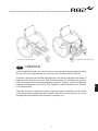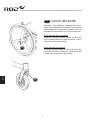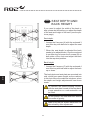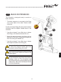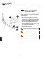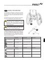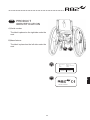
1
cheetah
TM
English user manual
G
B
© 2010 R82 A/S. All rights reserved.
The R82 logo and the Cheetah chairs are registered trademarks of R82 A/S.
05.2011 rev. 003
GB
G
B
CONTENTS
Safety................................................................................. 4
Tools................................................................................... 4
Maintenance....................................................................... 4
Warranty............................................................................. 5
Mounting and dismounting from the chair.......................... 5
Quick release..................................................................... 6
Foot support....................................................................... 7
Drum brake......................................................................... 8
Hand brake......................................................................... 9
Seat and back angling...................................................... 10
Back and seat width......................................................... 11
Seat depth and back height.............................................. 12
Back extension................................................................. 13
Seat extension and webbing............................................ 14
Anti-tip device................................................................... 15
Head support and helper's handle.................................... 16
Swing away side supports................................................ 17
Transfer arm rests and side plates................................... 18
Pommel............................................................................ 19
Side plates........................................................................ 20
Mudguards....................................................................... 20
Arm rests.......................................................................... 21
Tray.................................................................................. 22
Conversion kit................................................................... 23
Wheel combinations Cheetah 3-wheeler.......................... 24
Wheel combinations Cheetah 4-wheeler.......................... 25
Seat belt attachment........................................................ 26
Fix locks............................................................................ 26
Hip belt............................................................................. 28
Y-hip strap........................................................................ 28
Ankle straps...................................................................... 29
Foot straps....................................................................... 29
Transportation belt............................................................ 29
Transportation.................................................................. 30
Transportation in motor vehicles 1/2................................ 31
Transportation in motor vehicles 2/2................................ 32
Product identification........................................................ 33
Measurements.................................................................. 34
Technical data.................................................................. 35
Producer........................................................................... 35
Distributor......................................................................... 35
Care and maintenance..................................................... 36
Stain removal guide.......................................................... 37
Troubleshooting................................................................ 38
2
U.S. Patent No. US7,404,567 B2
GB
U.S. Patent No. US7,404,567 B2
CHEETAH
In choosing the Cheetah, we are sure that you have got an active wheelchair, which
will live up to any expectations one can have for a modern aid for children.
Cheetah is an active wheelchair, developed for the active child who both wants to
and can move around on its own. With this wheelchair, the child has every possibility of moving around and being together with other children, still with exeptional
seating comfort as the main focus. The Cheetah is delivered either as a 3-wheel
or 4-wheel model.
This user manual is meant as guide to assist the user in gaining the full benefit
of the many options offered by the Cheetah. Therefore we recommend you to go
through this manual before the Cheetah is put into use.
3
G
B
GB
SAFETY
The Cheetah has earned the CE-mark. This certifies that it meets all relevant European
safety requirements.
Further the Cheetah is approved according to EN 12182 and EN 12183. This manual is approved
according to ISO 7176-15 and EN 1041.
The durability of this product is 5 years when it is used on a daily basis. Hereafter the product
must be renovated (by R82 personnel) to extend the lifetime.
Remove the CE-mark, when rebuilding the product or when using other than original
R82 spare parts and fittings.
Never leave your child unattended in this product. Ensure constant supervision by
an adult. Incorrect use of the product, may cause serious injury to the user. Ensure
that the belt is securely fixed to the product before every use.
The chair is constructed for one user only. Do not place more than one user in the
chair.
The latest version of the manual is always available online: www.R82.com
GB
TOOLS
There is a tool bag at the back of the chair with 3, 4, 5 and 6 mm Allen keys. Use these tools
for the adjustments described in the manual. You will also find a set of reflector stickers
which may be adhered to the chair. We recommend that you place the reflector stickers on
the front by the front wheels, on the back under the seat and on the sides of the chair.
G
B
GB
MAINTENANCE
- Check the tyres regularly for air.
Air presure: 110 PSI/7,5 bar/750 kPa - 36 PSI/3,5 bar/350 kPa.
- Check the function of the hand brake regularly. Safety distance between the wheel and
the brake block is: 8-10 mm
- Clean the frame on a regular basis, especially when it has been in contact with rainwater
/ saline water.
Adjustments which are not described in this manual, must only be made by authorized
R82 personnel.
Oil the swing away parts, the turn handle and the spring boxes occasionally. We
recommend to use a synthetic teflon oil.
Do not use any cleaning materials containing chlorine or methylated spirit. Please
find the stain removal guide in the back of the manual.
4
GB
WARRANTY
R82 offers a 2-year warranty against defects in workmanship and materials
and a 5-year warranty on breakage of the metal frame caused by defects
in welds. The warranty would be adversely affected if the customer’s
responsibility of servicing and/or daily maintenance is not carried out according to the guidelines and intervals prescribed by the supplier and/or
stated in the manual. For further information, we refer to the R82 homepage/download. The warranty can only be sustained if the R82 product is
in use in the same country where it was purchased and if the product can
be identified by the serial number. The warranty does not cover accidental
damage, including damage caused by misuse or neglect. The warranty
does not extend to non-durable parts, which are subject to normal wear
and tear and need periodic replacement. The warranty is null and void if
non-original R82 parts/accessories are used, or if the product is repaired
or altered by anyone other than an authorised R82 representative or by
trained personnel officially recognised by R82 for repair and maintenance of
R82 products. R82 reserves the right to inspect the product being claimed
for and the relevant documentation before agreeing to the warranty claim,
and to decide upon whether to replace or repair the defective product. It
is the customer’s responsibility to return the item being claimed for under
warranty to the address of purchase. The warranty is given by R82 or,
subsequently, an R82 dealer.
GB
MOUNTING AND DISMOUNTING
FROM THE CHAIR
Instructions about getting in and out of the wheelchair are given by R82
representatives when the Cheetah is purchased.
Before placing the user into the Cheetah the brake has to be locked in place.
Place the user into the Cheetah and adjust the accessories to achieve the
optimal seating for the child.
Further, go to the pages concerning transfer arm rest and side plate.
5
G
B
GB
QUICK RELEASE
Cheetah is, as standard, supplied with removable Quick Release push wheels, which means
fast and easy dimounting of the wheels, when for
example the wheelchair has to be transported.
Quick Release driving wheels:
Push and hold the release button (A) and pull
out the wheel. Make sure that the wheel "clicks"
into place when remounting.
A
G
B
Quick Release front wheel:
Push the release button (B) and pull down the
front fork and wheel. Make sure that the wheel
"clicks" into place when remounting.
B
6
GB
FOOT SUPPORT
The Cheetah is delivered with foot supports
mounted as standard.
Loosen the screws (A) with the enclosed 6 mm
Allen key to angle the foot plate. Angle the foot
plates individually.
The foot plates can be equipped with straps
when needed (B).
B
Watch out not to get the feet caught in the
gab between the foot plates.
A
G
B
7
GB
The Cheetah, 3-wheels is as standard delivered
with drum brake (A). The brake does not require
any maintenance.
B
A
DRUM BRAKE
Pull back the brake (B) to activate, and push
forwards (C) to deactivate.
C
Follow the instructions below to mount wheels
with drum brake on the Cheetah 4-wheeler.
* Loosen the nut (D) to remove the push wheel.
Mount the new wheel with drum brake and
fasten the nut.
Fasten the pointed screw (E) at the hub, if
the drum brake does not brake enough.
D
The position of the rear wheels must not be
changed, as the wheelchair will be tilting.
The position must always stay the same
as delivered from R82.
When mounting the wheel, make sure that
it "clicks into place" and that the brake
function correctly.
G
B
E
8
GB
HAND BRAKE
The Cheetah, 4-wheels is delivered with a hand
brake as standard.
B
The brake is simple to use. Push the handle
forwards (A) to activate and pull the handle back
(B) to deactivate the brake.
D
A
The hand brake is mounted in a fitting on the
frame. Move the fitting forwards or backwards,
according to how tight the brake should be.
When the fitting is moved backwards, the brake
will be tighter. Move the fitting forwards and the
brake will be looser.
C
Loosen the 4 screws (C) with the enclosed 4
mm Allen key to adjust the hand brake. Fasten
the screws in the position required.
Keep the recommended air pressure, 110
PSI/7,5 bar in the driving wheels, to make
the brakes work properly.
Keep the recommended safety distance,
8-10 mm, between the wheel and the brake
block.
G
B
Watch out not to get your fingers caught at
position (D), when activating the brake.
9
GB
SEAT AND BACK
ANGLING
Seat ramp:
The seat and back angles in one movement.
Turn the handle (A) under the seat to adjust the
exact position of the chair.
Oil the turn handle (A) occationally.
Angling the back:
To adjust the angle, pull out the strap (B). The
back will angle all the way down to the seat,
which makes the chair take up minimum space,
for instance, during transportation.
A
Hold on to the back to prevent it from suddenly moving when the strap is pulled.
Remove the transfer arm rests and side
plates, if any, to fold the back all the way
down to the seat.
Oil the spring boxes (C) occationally.
B
G
B
C
10
GB
BACK AND SEAT
WIDTH
A
The Cheetah has width adjustment in back and
seat.
D
* Loosen the 4 screws (A) with the enclosed 5
mm Allen key to adjust the back width.
40 cm
36 cm
32 cm
28 cm
* Loosen and dismount the 8 through-going
screws (B) with the enclosed 5 mm Allen key
to adjust the seat width.
* Loosen and dismount the 13 screws (C) with
the enclosed 4 and 5 mm Allen keys to adjust
the frame width.
B
Back and seat width:
Adjust the back and seat width according to the
marks (D).
D
40 cm
36 cm
32 cm
28 cm
Frame width:
Adjust the frame width according to the mark
(E). If seat and back width are adjusted to 36
cm, the frame width must be adjusted to 3 (36
cm). With this adjustment, there will be room for
sideplates ect.
C
G
B
The four marks in respect of the seat and
back must be the exactly the same.
The marks in frame width must be exactly
the same in both sides of the chair.
Do not go beyond the max. indication when
adjusting the width of the seat and back.
1
Make sure that all screws (A+B+C) have
been fastened safely after adjustment.
2
3
E
New cushions can be ordered as an accessory.
11
4
max
GB
SEAT DEPTH AND
BACK HEIGHT
If you need to adjust the width of the back or
seat, please do this before you adjust the depth
of the seat and height of the back (see the previous page).
A
Seat depth:
* Loosen the 8 screws (A) with the enclosed 3
mm Allen key with ball end to adjust the seat
depth.
* When the seat depth is adjusted the back
needs to be adjusted also. Use the enclosed
4 mm Allen key to loosen the 2 screws (B) on
both sides of the chair and adjust the back
into the required position.
B
Back height:
* Loosen the 8 screws (C) with the enclosed 4
mm Allen key with ball end to adjust the back
up or down.
G
B
The back plate and seat plate are mounted into
rails, which have same length as the cushions
in the chair. Move the cushions into place, when
the depth and height adjustments have been
made.
C
To maintain the optimal seating comfort,
with the seat plate moved all the way back,
a seat extension or a web extension can
be fitted.
Do not position the seat and back behind
the centre of gravity.
Make sure that all screws have been fastened safely after adjustment.
12
GB
BACK EXTENSION
The Cheetah is designed ready to receive a
back extension
* The back extension is mounted in the fitting
(A) on the back of the chair. Fasten when
mounted.
Use the enclosed fitting (B) when both the back
extension and the helper's handle have to be
mounted.
C
* Use the enclosed 3 mm Allen key to fasten
the fitting on the back extension bar (C).
A
* Mount the back extension in the fitting (A) on
the back of the chair. Fasten the fitting (B) on
the chair using the handle (D).
B
E
D
* Use the enclosed 3 mm Allen key to fasten
the helper's handle in the fitting (E).
Be aware that the release button activates when the helpers handle has been
mounted in either fitting (A) or (B).
Be carefull not to get your fingers caught
when adjusting the height and depth of the
head support.
G
B
Do not ever use the helpers handle to lift/
pull the wheelchair up or down from stairs,
landings, curbs ect. The wheelchair can
only be lifted by two persons grabbing hold
of the frame. Never use the helpers handle
to lift the wheelchair.
13
GB
The seat depth is adjustable to fit almost any
needs. Further, it is possible to mount a seat or
a web extension.
C
E
SEAT EXTENSION
AND WEBBING
* Remove the end piece (A) from the rails.
* Mount the seat extension in the bottom inside
groove of the rails (B). Fasten the seat extension, using the enclosed 3 mm Allen key (C).
D
* Mount the webbing in the top groove of the
rails (D) and secure as shown (E).
* Remount the end pieces.
B
Cheetah, seat width 32, 36 and 40 cm, are
supplied including the seat extension.
A
The seat and web extensions have to be
adjusted when the seat depth is changed.
We recommend to use either/and the seat
extension and webbing on the Cheetah 32,
36 and 40 cm, to avoid the risk of the user
dropping forwards.
G
B
14
GB
ANTI-TIP DEVICE
As standard the Cheetah is delivered including
the anti-tip device. Mount the anti-tip device in
the fitting (A) under the seat and fasten with the
Allen key.
Activate the anti-tip device with the foot at position (B). To deactivate, turn it around 180°.
The anti-tip device always has to be
activated when the wheelchair is tilted.
However, the anti-tip device has to be
deactivated or removed when the chair is
being transported.
A
We recommend regular checking of the
function of the anti-tip device. The wheelchair can tilt at some adjustments.
B
Depending on the size of the wheels, the
Cheetah is supplied with either short or long antitip. Follow the instructions below when changing
the wheel position or size. The product codes for
the anti-tip safety are listed under Accessories
at the end of the manual.
Cheetah 3-wheeler
20” rear wheel /
anti tip device
22” rear wheel /
anti tip device
24” rear wheel /
anti tip device
Wheel placement pos.1
Wheel placement pos.2
4” wheel / SHORT
6” wheel / SHORT OR LONG
6” wheel / SHORT OR LONG
-
-
Wheel placement pos.1
Wheel placement pos.2
Wheel placement pos.3
-
4” wheel / SHORT OR LONG
6” wheel / LONG
4” wheel / SHORT OR LONG
6” wheel / SHORT OR LONG
-
6” wheel / SHORT OR LONG
-
Wheel placement pos.1
Wheel placement pos.2
Wheel placement pos.3
-
-
4“ wheel / LONG
-
4” wheel / LONG
-
4” wheel / SHORT OR LONG
-
Cheetah 4-wheeler
20” rear wheel /
anti tip device
22” rear wheel /
anti tip device
24” rear wheel /
anti tip device
Wheel placement pos.1
4” wheel / SHORT
-
-
Wheel placement pos. 1
Wheel placement pos. 2
Wheel placement pos. 3
-
4” wheel / SHORT OR LONG
6” wheel / LONG
4” wheel / SHORT
6” wheel / SHORT OR LONG
-
6” wheel / SHORT OR LONG
-
Wheel placement pos. 1
Wheel placement pos. 2
Wheel placement pos. 3
-
-
4” wheel / LONG
-
4” wheel / SHORT OR LONG
-
4” wheel / SHORT OR LONG
-
15
G
B
GB
HEAD SUPPORT
AND HELPER'S
HANDLE
The Cheetah is designed ready to receive head
support and helper's handle.
C
A
B
* The head support or the helper's handle is
mounted in the fitting (A) on the back of the
chair. Fasten when mounted.
E
Use the enclosed fitting (B) when both the head
support and the helper's handle have to be
mounted.
D
* Use the enclosed 3 mm Allen key to fasten
the fitting on the head support bar (C).
* Mount the head support in the fitting (A) on
the back of the chair. Fasten the fitting (B) on
the chair using the handle (D).
* Use the enclosed 3 mm Allen key to fasten
the helper's handle in the fitting (E).
Be aware that the release button activates when the helpers handle has been
mounted in either fitting (A) or (B).
G
B
Be carefull not to get your fingers caught
when adjusting the height and depth of the
head support.
Do not ever use the helper's handle to
lift/pull the wheelchair up or down from
stairs, landings, curbs ect. The wheelchair
can only be lifted by two persons grabbing
hold of the frame. Never use the helper's
handle to lift the wheelchair.
16
GB
SWING AWAY SIDE
SUPPORTS
B
Swing away side supports can be mounted on
the Cheetah. Follow the below instructions to
mount the side supports correct:
A
* Mount the fittings (A) for the side supports
into the rails (B) and fasten at the required
height.
* Adjust the swing away side supports into the
required position.
We recommend to oil the swing away parts
occasionally.
C
The vertical rails on size 28 cm and 32 cm can
be replaced with longer rails, if needed. Please
order the new rails on order no. 900350-2
* Loosen the two screws (C) on both sides of
the chair to dismount the vertical rails. Use
the enclosed 4 mm Allen key.
* Mount the new, longer rails and fasten the
screws.
G
B
* Mount the side supports as described above.
17
GB
A
B
TRANSFER ARM
RESTS AND SIDE
PLATES
It is possible to mount transfer arm rests on the
Cheetah. The transfer arm rests make it easier
for the user to get in and out of the chair.
Mount the transfer arm rests and the side plates
in the rails in the back (A) and in the seat (B).
* Loosen the screw (C) to adjust the angle.
Remove the transfer arm rests when the back
has to be angled all the way down to the seat:
C
* Loosen the screw (C) and remove the transfer
arm rest from the rails in the back rest.
* The transfer arm rest does not have to be
dismounted from the rails in the seat.
Be carefull not to get your fingers caught
between the side plates and the driving
wheels.
G
B
18
GB
POMMEL
A pommel can be mounted on the Cheetah.
* Mount the pommel in the seat or the seat
extension and tighten under the seat (A).
A
G
B
19
GB
B
SIDE PLATES
The side plates can be mounted on the
Cheetah.
Follow the instructions below to mount the side
plates correctly:
A
1)Remove the end pieces from the chair front (A)
C
2)The side plate bracket (B) must be placed in
the seat rails and fastened by tightening the
Allen screws (C)
3)Remount the end pieces
The side plates can be depth adjusted by loosening the Allen screws (C).
The side plates can be dismounted easily from
the bracket by lifting the side plate.
GB
G
B
MUDGUARDS
Mudguards can be mounted on the Cheetah.
Follow the instructions below to mount the mudguards correctly:
B
A
1)Remove the end piece from the chair front (A)
2)The mudguard fitting must be placed in the
seat rail and fastened by tightening the Allen
screws (B)
C
3)Remount the end pieces
4)Mount the mudguard in the fitting and fasten
by tightening the screw (C).
20
GB
ARM RESTS
B
Angle and height adjustable arm rests can be
mounted on the Cheetah. The arm rests come
in two sizes; 20 and 30 cm
A
Follow the instructions below to mount the arm
rests correctly:
C
1)Remove the end pieces at the top of the back
rails
2)Mount the arm rests (B) in the rails so the arm
rests are in vertical position.
3)Tip the arm rests approximately 10cm back
and then forth to the position needed.
4)Remount the end pieces.
The arm rests can be angled and height adjusted
by loosening the Allen screw (C).
Please make sure that the spring washer is
centered on the spacer (D) when the Allen
screw is tightened.
D
21
G
B
GB
TRAY
The Cheetah tray will be delivered unassembled
and can be used for all the sizes.
A
Follow the instructions below to mount the tray
correctly:
C
1)Remove the end pieces in front of the arm
rests.
2)Mount the brackets on the tray top by using
the screws and nuts enclosed (B).
3)Lead the brackets into the arm rests and
tighten with the finger screw (C).
The brackets can be turned each way depending on the chair size of which the tray should
be used.
B
G
B
22
GB
CONVERSION KIT
The Cheetah may be converted from a 3-wheel
to a 4-wheel model. To ensure correct conversion, please follow the description below:
1.Remove the driving wheel and the anti-tip,
where these are used.
1
2.Remove the bottom of the framework by
loosening and removing the 15 screws.
2
3.Remove the suspension, centre stem and foot
rests.
3
4.The new centre stem is installed and the bottom of the framework is loosely fitted. The
centre stem may be turned to either lower or
raise the foot rests.
5.The sides of the frame are installed and all
screws are tightened again. Install the driving
wheel and the anti-tip, if any, and turn the chair
over.
4
Remember to adjust the wheels to the
same width in both sides.
5
6
6. Replace the covers on the foot rests.
7. Remove the bolt and install the foot rests. Put
the bolt back on and tighten it.
7
8. Put a plug at the end of the centre stem.
Your new 4-wheel Cheetah is ready for use!
See the list at the end of the manual for
ordering conversion kits.
23
8
G
B
WHEEL COMBINATIONS
CHEETAH 3-WHEELER
GB
1
Changing the location of the driving wheel:
1. Remove the driving wheel.
2. Loosen the nut with a 24 mm open-end wrench.
3. Move the wheel sleeve to the position you want.
Fasten the nut and install the driving wheel.
2
3
Replacing the centre stem:
4. Remove the bottom of the framework by loosening
the 15 screws.
5. Replace the centre stem and re-tighten the 15
screws.
6. Replace/install the front wheel by loosening the
screw with a 6 mm Allen key.
Use the form below to find the right seat height for
the wheels and centre stem chosen.
4
We recommend that you regularly check the
air pressure in the tires.
We recommend that you regularly ensure
that the centre stem is properly fastened to
the frame.
5
Depending on the wheel size and position,
there may be a risk of instability when forcing
small obstacles.
6
G
B
Cheetah 3-wheeler
20” rear wheel / 22” rear wheel / 24” rear wheel /
seat height *
Wheel placement pos.1
Center bar, short
4” wheel/44-50 cm 6” wheel/47-53 cm -
Wheel placement pos.2
Center bar, short
6” wheel/47-53 cm -
Wheel placement pos.1
Center bar, pos.1
-
Wheel placement pos.2
Center bar, pos.1
4” wheel/47-53 cm 6” wheel/50-56 cm -
Wheel placement pos.3
Center bar, pos.1
6” wheel/50-56 cm -
-
Wheel placement pos.1
Center bar, pos.2
-
-
4” wheel/50-56 cm
Wheel placement pos.2
Center bar, pos.2
-
4” wheel/50-56 cm -
Wheel placement pos.3
Center bar, pos.2
4“ wheel/50-56 cm -
seat height *
-
4” wheel/47-53 cm 6” wheel/50-56 cm
Due to safety reasons other than the described possibilities can not be used !
* The seat height is measured at the front of the chair and is depending on the seat angle.
24
seat height *
-
GB
WHEELCOMBINATIONS
CHEETAH 4-WHEELER
Changing the location of the driving wheel:
1. Remove the driving wheel.
2. Loosen the nut with a 24 mm open-end wrench.
3. Move the wheel sleeve to the position you want.
Fasten the nut and install the driving wheel.
1
2
3
Changing the position of the front wheel:
4. Loosen the nut with a 13 mm open-ended wrench.
5. Move the front wheel to the position required. Refasten the nut.
Changing the front fork:
6. Remove the front wheel and loosen the nut with a 13
mm open-ended wrench. If the front fork has quick
release, please use this. The front fork is replaced
and everything is tightened.
Use the form below to find the right seat height for the
wheels and centre stem chosen.
6
We recommend that you regularly check the air
pressure in the tires.
5
We recommend that you regularly ensure that
the centre stem is properly fastened to the frame.
4
Depending on the wheel size and position, there
may be a risk of instability when forcing small
obstacles.
Cheetah 4-wheeler
20” rear wheel / 22” rear wheel / 24” rear wheel /
seat height *
Wheel placement pos.1
Front fork 1
4” wheel/44-50 cm -
Wheel placement pos.1
Front fork 2
-
Wheel placement pos.2
4” wheel/47-53 cm 6” wheel/50-56 cm -
Wheel placement pos.3
6” wheel/50-56 cm -
-
Wheel placement pos.1
-
-
4” wheel/50-56 cm
Wheel placement pos.2
-
4” wheel/50-56 cm -
Wheel placement pos.3
4” wheel/50-56 cm -
seat height *
seat height *
-
4” wheel/47-53 cm 6” wheel/50-56 cm
Front fork 3
Due to safety reasons other than the described possibilities can not be used !
* The seat height is measured at the front of the chair and is depending on the seat angle.
25
-
G
B
GB
C
A
SEAT BELT
ATTACHMENT
* Mount the two belt fittings (A), for the seat belt,
in the slots on the back side of the seat.
* Mount the ends of the seat belt (B) in the fittings and fasten in the snap locks (C).
B
* Secure the user in the wheelchair and fasten
the seat belt using the buckle (D).
B
* Pull the strap (E) until the seat belt is secured
in the correct position.
D
E
Take care that all the fixations and adjustments are placed and fitted correctly and
check it on a regular basis.
GB
A
FIX LOCKS
Fix locks can be mounted different places on
the seat unit.
A
* Two fix locks can be mounted on the back
with with the enclosed screws.
* Two fix locks can be mounted on the side
plates with the enclosed screws.
G
B
* Two fix locks can be mounted in the back
or seat rails with the enclosed fitting (A) and
screws.
Take care that all the fixations and adjustments are placed and fitted correctly and
check it on a regular basis.
26
A
G
B
B
Use this drawing together with the descriptions on the following pages.
27
GB
HIP BELT
Mount the fixlocks in the seat. See page 26.
The hip belt can be opened and closed by using
the buckles.
B
Follow the instructions below, with help from
page 27.
* Mount the straps in the fixlocks (B).
Take care that all the fixations and adjustments are placed and fitted correctly and
check it on a regular basis.
GB
Y-HIP STRAP
Mount the fixlocks in the seat. See page 26.
G
B
The Y-hip strap can be opened and closed by
using the buckles.
Follow the instructions below, with help from
page 27.
D
* Mount the straps (D) in the belt fittings at the
back of the seat (B).
* Mount the straps (C) in the fixlocks in the seat
rails.
C
Take care that all the fixations and adjustments are placed and fitted correctly and
check it on a regular basis.
28
GB
ANKLE STRAPS
A
The ankle straps can be opened and closed by
using the velcro or the buckle (A).
Follow the instructions below for mounting.
* Remove the buckles (C).
* Pull the straps (B) through the slides in the
foot plates.
* Mount the buckles (C) again and make sure
the straps do not slide off.
B
C
Take care that all the fixations and adjustments are placed and fitted correctly and
check it on a regular basis.
GB
FOOT STRAPS
The foot straps can be opened and closed by
using the velcro or the buckle (A).
Follow the instructions below for mounting.
* Open the straps and pull them (A) through
the slides in the foot plates.
* Close the straps around the users foot.
A
G
B
Take care that all the fixations and adjustments are placed and fitted correctly and
check it on a regular basis.
GB
TRANSPORTATION
BELT
The belt goes around the persons chest and
around the back of the chair. Use the velcro for
closing the belt and lock with the metal lock.
Take care that all the fixations and adjustments are placed and fitted correctly and
check it on a regular basis.
29
GB
TRANSPORTATION
It is possible to fold the Cheetah wheelchair for
transportation or storage.
* Dismount the driving wheels (A) (see the page
concerning quick release).
* Dismount the front wheels if they are equipped with quick release (B).
A
* Fold the back forward (C) (see the page concerning seat and back angle)
* Lift the Cheetah safely, for instance into a car,
by grapping around the seat unit (D).
B
Do not lift the Cheetah at the wheels.
C
G
B
D
D
30
GB
TRANSPORTATION
IN MOTOR
VEHICLES 1/2
The Cheetah wheelchair is approved for transporting people in motor vehicles, when the
wheelchair is placed in forward-facing position.
The approval is not valid on special made
chairs.
Restraints should not
be held away from
body by wheelchair
components such
as side plates
or wheels.
Follow the below to ensure the safety:
The user should transfer to the vehicle
seat and use the vehicle-installed restraint
system whenever it is feasible.
The wheelchair must be placed in forwardfacing position, when used as a seat in a
motor vehicle. Use an approved 4-point
strap-type tiedown system.
The seat must be placed in horizontal
position. The back must be 90° or perpendicular to the seat.
Use an approved 3-point belt in the wheelchair. Restraints should not be held away
from the body by wheelchair components
such as side plates or wheels.
G
B
All accessories must be removed from
the wheelchair and secured separately in
the vehicle. Accessories which can not be
removed, must be secured to the wheelchair but positioned away from the user
with energy-absorbing padding placed
between the accessories and the user.
The wheelchair should be inspected by the
dealer before re-use following involvement
in any type of vehicle impact.
31
GB
TRANSPORTATION
IN MOTOR
VEHICLES 2/2
Secure the Cheetah in the vehicle:
* Mount the 4-point strap-type tiedown system
in the vehicle. (Follow the manufacturer's
instructions).
* Mount the fittings (A) with the symbol (C) on
the back of the chair.
D
Please be aware of the left/right transport
fittings. The small side wing (D) must be
fixated in the wheel fitting.
B
* Mount the fittings (B) with the symbol (C) on
the front of the chair.
* Secure the wheelchair to the vehicle, using the
4-point strap-type tiedown system. Use either
a hook or a strap in the fittings (A) and (B).
A
E
C
Use a 4-point strap-type tiedown system
approved according to ISO 10542-2.
Secure the user in the wheelchair:
55°
G
B
* Use the 3-point belt as shown on the drawing
(E).
* The angle on the 3-point belt has to be according to drawing (F).
* The belt restraints should be adjusted as
tightly as possible, consistent with user comfort. Further the belt webbing should not be
twisted when in use.
F
Use a hip-belt and a 3-point belt approved
according to ISO 10542-1 or SAE J2249.
30°
When transporting children by car, the
Cheetah wheel chair is approved for a max.
load / user weight of 57 kg
75°
32
GB
PRODUCT
IDENTIFICATION
A)Serial number
The label is placed on the right side under the
seat.
B)Manufacturer
The label is placed on the left side under the
seat.
B
A
Dato: 31-01-02
SN:
Varenr:
A
Belast: kg
0840-01-111878-001
880003
5707292
B
G
B
Parallelvej 3
DK-8751 Gedved
33
134158
J
A
B
I
E
D
G
GB
G
B
H
MEASUREMENTS
3-wheeler; seat width
28 cm
32 cm
36 cm
40 cm
Seat width (A)
28-32 (11-12½”)
32-36 (12½-14”)
36-40 (14-15½”)
40 (15½”)
Seat depth (B)
24-29 (9¼-11¼”)
30-35 (11¾-13¾”)
35-40 (13¾-15½”)
40-45 (15½-17”)
Back height (C)
25-28 (9¾-11”)
25-28 (9¼-11”)
28-35 (11-13¾”)
28-35 (11-13¾”)
Lower leg length, max * (D)
33 (12¾”)
33-35 (12¾-13¾”)
42-46 (16½-18”)
42-46 (16½-18”)
Seat height above floor, front * (E)
50 (19½”)
50-53 (19½-20¾”)
50-55 (19½-21½”)
50-56 (19½-21¼”)
Back width
28 (11”)
32 (12½”)
36 (14”)
40 (15½”)
Width (G)
57 (22¼”)
61 (23¾”)
65 (25¼”)
69 (27”)
Length (H)
90 (35”)
90 (35”)
90 (35”)
90 (35”)
Height (I)
76 (29¾”)
76 (29¾”)
82 (32”)
82 (32”)
Width inside between wheels,top (J)
33 (12¾”)
37 (14½”)
41 (16”)
45 (17½”)
Depth seat cushion
29 (11¼”)
35 (13¾”)
41 (16”)
45 (17½”)
Height back cushion
25 (9¾”)
25 (9¾”)
25 (9¾”)
25 (9¾”)
Weight
10 kg (22 lb)
10 kg (22 lb)
10 kg (22 lb)
10 kg (22 lb)
Max. load / user weight
75 kg (165 lb)
75 kg (165 lb)
75 kg (165 lb)
75 (165 lb)
4-wheeler; seat width
28 cm
32 cm
36 cm
40 cm
Seat width (A)
28-32 (11-12½”)
32-36 (12½-14”)
36-40 (14-15½”)
40 (15½”)
Seat depth (B)
24-29 (9¼-11¼”)
30-35 (11¾-13¾”)
35-40 (13¾-15½”)
35-40 (13¾-15½”)
Back height (C)
25-28 (9¾-11”)
25-28 (9¾-11”)
28-35 (11-13¾”)
28-35 (11-13¾”)
Width b.wheels,top,wo.drumbrakes(D)
35 (13¾”)
39 (15¼”)
43 (16¾”)
47 (18¼”)
Seat height above floor, front * (E)
50 (19½”)
50-53 (19½-20¾”)
50-55 (19½-21½”)
50-56 (19½-21¾”)
Back width
28 (11”)
32 (12½”)
36 (14”)
40 (15½”)
Width, without drumbrakes (G)
59 (23”)
63 (24½”)
67 (26¼”)
71 (27¾”)
Width, with drumbrakes
57 (22¼”)
61 (23¾”)
65 (25¼”)
69 (27”)
Length (H)
77 (30”)
77 (30”)
77 (30”)
77 (30”)
Height (I)
76 (29¾”)
76 (29¾”)
82 (32”)
82 (32”)
Lower leg length, max * (J)
35 (13¾”)
35-37 (13¾-14½”)
44-48 (17¼-18¾”)
44-48 (17¼-18¾”)
Width b.wheels, top,w.drumbrakes.
33 (12¾”)
37 (14½”)
41 (16”)
45 (17½”)
Height back cushion
25 (9¾”)
25 (9¾”)
25 (9¾”)
25 (9¾”)
Depth seat cushion
29 (11¼”)
35 (13¾”)
41 (16”)
45 (17½”)
Weight
11 kg (24 lb)
11 kg (24 lb)
11 kg (24 lb)
11 kg (24 lb)
Max. load / user weight
75 kg (165 lb)
75 kg (165 lb)
75 kg (165 lb)
75 (165 lb)
Max. load / user weight at transportation
57 kg (125,5 lb)
57 kg (125,5 lb)
57 kg (125,5 lb)
57 kg (125,5 lb)
* Dependent on the seat angle
Angles:
-10° - 28°
Back
Seat
0° - 20°
0° - 105°
Foot support bar
6°
Camber
The Cheetah is measured according to ISO 7176-5 and 7176-7 with the following wheel combination: 24” rear wheel and 6” front wheel. We supply
various types of driving wheels, which is why the weight is listed without the driving wheels. Different settings than described in the standard, may
result in another measuring.
34
GB
TECHNICAL DATA
Frame:
Powder lacquered aluminium pipes
Cushions: Fire resistant foam
Cover:
Fire resistant microfibre material
Plastic parts:PA6
GB
PRODUCER
R82 A/S
Parallelvej 3
8751 Gedved
Denmark
GB
DISTRIBUTOR
Please find your distributor on www.R82.com
G
B
35
GB
CARE AND MAINTENANCE
UPHOLSTERY
The upholstery is made of fire resistant foam and comfort material. The upholstery can easily be
removed from the cushion and can be machine washed at 30°. Further, regular vacuum cleaning
and brushing will help to preserve the fabric's colour and appearance.
WHEELS
Tyres: Check the air pressure (recommended: 110 PSI/7,5 bar/750 kPa) and tread at least once a
month.
Wheel axles: The axles should be kept free of dirt. Clean as neccessary.
Ball bearings: The ball bearings require no maintenance.
Handrims: If a handrim should be damaged in such a way that it could lead to hand injury, it should
be replaced.
BRAKES
The function of the brakes is dependent upon tyre pressure. Encrusted dirt can have a negative
effect on the brake mechanism. The brakes should be checked at least once a month.
FRAME
Fasten all screws underneath the chair on a regular basis, especially when the chair has been
changed from one width to another. Further, it is important to keep the wheelchair clean, both for
your own comfort and the longevity of the chair. Especially be aware to clean the holes for the back
angling. Wash the chair with car shampoo or washing-up liquid. If the chair is particularly dirty, a
grease remover can be used.
INSPECTION
It is important to fasten all screws on the chair on a regular basis. Especially the screws in the back,
G seat and seat extension have to be checked when modifications on the width has been made. All
screws which secure the accessories have to be checked, at least once a month. To avoid sharp
B
corners, it is important to check that all rail-ends are equipped with end pieces. Further, it is important to be aware of any indications of beginning faults on the frame, PVC parts and the like.
REPAIR
If there is a fault on your wheelchair you should contact your dealer at once. Defective chairs
should not be used. If your chair needs reconditioning or repair, only original R82 parts must be
used. Accessories or available spare parts which are broken can be forwarded to R82 for repair.
If fault in the fundamental parts, the hole chair need to be returned to R82 for repair. R82 will not
be held responsible for damage or injury caused by use of non-original parts or repairs made by
a non-authorized R82 person.
36
GB
STAIN REMOVAL GUIDE
BLOOD
Was off blood with cold water. If this fails to help, add a neutral kitchen detergent.
INK
Remove as much as possible with absorbent paper. Clean with 20% denatured alcohol and wash
with water to which a neutral kitchen detergent has been added.
CHOCOLATE AND CONFETIONARY
Dab with lukewarm water
GRASS AND VEGETABLES
Dab with lukewarm water with or without a neutral kitchen detergent.
COFFEE, TEA AND MILK
Remove as much as possible with absorbent paper. Dab with water containing a neutral kitchen
detergent.
BALLPOINT PEN AND COSMETICS
Clean with alcohol
NAIL POLISH
Dab with nail polish remover. Use acetone if this fails to help.
OIL AND GREASE
First sprinkle talcum on the spot and leave. Then brush away. Finally, dab carefully with a cloth
mostened with benzen or alcohol.
SHOE POLISH
Dab carefully with a cloth moistened with benzene or alcohol.
JAM, SYRUP, FRUIT AND JUICE
First remove as much as possible with a spoon. Then dab with lukewarm water.
WINE AND SPIRITS
First remove as much as possible with absorbent paper. Then dab with water containing a neutral
kitchen detergent. Finally, rinse with denatured alcohol.
PAINT, OILBASED
First clean with turpentine. Then dab with water containing a neutral kitchen detergent. Seek expert advice if the spot is old.
PAINT, WATERBASED
Dab with cold water containing a neutral kitchen detergent. Seek expert advice if the spot is old.
37
G
B
GB
TROUBLESHOOTING
Problem*
Solution
Wheelchair will not hold a
straight course
- Inflate the tyres
- Check the front fork attachments angle
- Check that the front fork attachments are mounted at the same
height
- Rear wheel mountings are incorrectly fitted
- The user is distributing weight unevenly
- More strength being used on one side than the other when propellning the chair
Wheelchair feel heavy to
propel
-
-
-
-
Inflate the tyres
Rear wheel mountings are incorrectly fitted
Ensure that the castor axles are free from dirt etc.
Too much weight over the castors. Adjust the centre of balance
Wheelchair feels heavy to
turn
-
-
-
-
-
Inflate the tyres
Check that the front fork attachments are not to tightly fastened
Adjust the angle of the front fork attachments
Ensure that the castor axles are free from dirt etc.
Too much weight over the castors. Adjust the centre of balance
Brakes not effective
- Inflate the tyres
- Adjust the distance between brake and tyre
Rear wheels loose
- Ensure that the axle-shaft washer is in place
- Adjust the length of the axle shaft
Rear wheel hard to remove/ replace
- Clean and lubricate quick release
- Adjust the length of the axle shaft
G Castor wobbles
B
Wheelchair feels awkward
Drum brake, does not brake enough
The Back angling function
does not fit into place.
- Front forks are not tightly fitted
- Check that the front fork attachments are mounted at the same
height
- Adjust the angle of the front fork attachment
- Too much weight over the castors. Adjust the centre of balance
- Inflate the tyres
- Check that all screws, nuts and bolts are properly fastened
- Fasten the pointed screw at the hub.
- The chair is put wrong together. Measure the chair and fasten the
screws with the chair in the correct position.
* The user may experience several of these problems in a wheelchair that is incorrectly adjusted
or is being incorrectly used.
38