1
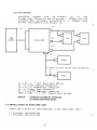
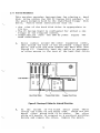
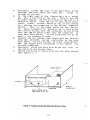
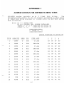
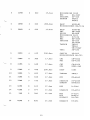
LCS·6200 SERIES WINCtBTER DISK CONTROLLER USER'S MANUAL CONTENTS Chapter 1. 1.1 1.2 1.3 INTRODUCTION General Description 1.1.1 LCS-6210 1.1.2 Other Derivatives Minimum System Requirements Optional Software Requirements Chapter 2. 2.1 2.2 2.3 2.4 2.5 2.6 2.7 2.8 2.9 • 1 1 2 3 3 4 HARDWARE INSTALLATION Preliminary Setup Opening the System Unit Initial Setup of LCS-6200 Series Board Connection of LCS-6200 Series in System Unit Setup of Hard Disk Drive. Set Up Floppy Disk Drives 2.6.1 For LCS-6210 2.6.2 For LCS-6220 Installation of Hard Disk Unit 2.7.1 Internal Installation 2.7.2 External Installation Closing the System Unit Reconnection of Cables to External Devices Chapter 3. INITIAL POWER UP Chapter 4. FORMATTING THE WINCHESTER DISK Chapter 5. LOCKING BEFORE MOVING Appendix 1. 2. 3. Trademarks: 4 4 4 7 7 7 7 8 8 9 11 11 ~ 11 12 • • • • • • • Switch settings for different Drive Types Diagnostics About LCS-6200 Series About Concurrent CP/M-86 • • • • • • • • • 1. 2. 3. 4. 5. IBM PC/XT, PC-DOS: IBM Corp. CCP/M-86: Digital Research, Inc. MS-DOS: Microsoft Corp. ST-506, ST-412: Seagate Technology. COMPAQ: Compaq Computer Corp. • •• 13 16 17 20 21 CHAPTER 1 INTRODUCTION 1.1 GENERAL DESCRIPTION The LCS-6200 Series Winchester disk controller is an IBM PC/XT compatible Winchester Controller board designed to interface up to two 5 1/4 inch Hard Disk drives, two 5 1/4 inch Floppy Disk drives and also provides for Streaming Tape backup. Hard Disk interface is via the Seagate ST-506/ST-412 interface. Floppy Disk interface is vi~ the IBM PC standard floppy interface and Streaming Tape Backup is via the QIC-02 or SA-450 interface. 1.1.1 LCS-6210: A Winchester disk controller for computers. IBM PC/XT FEATURES: * * Compatible with IBM PC/XT host bus. Controls up to 2 hard disk drives via the industry standard ST-506/ST-412 disk interface. * On-board error checking and correction guarantee maximum data integrity. * reduced On-board precompensation. * On-board disk BIOS ROM with automatic booting. * Automatic retries during disk access. * Split mode which allows one split into two logical drives. * High level command set supported. * * Up to 15 different drive types can be chosen. write current (ECC) and to write physical drive to be Drives that implement the "Servo Wedge" imbedded servo scheme at index can also be handled. o .... ,...,Q) ,..., ....... = o u Q) ... .c o ..... Q) .. = ... .........0 Q) .....U .... OS Q) Q) Q) .... ....... OS U ,...,~ p.. ., .e~ ~ ~ g M - ) 170 x 100 0.8A 1 I 1 ) LCS-6220 514" x 2 - 1.0A 50mA 317 x 122 1 I 1 Standard 512 Bytes Yes I J LCS-6228 - QIC·02 1.0A COMPAQ 1 1 1 352 x 122 I LCS-6238 QIC.()2 514" x 2 1.4A Advanced Diagnostics PC·DOS 2.0,2.1, 3.0, 3.1, CCP/M·86, CP/M-86 I J IBM Advanced Diagnostics V2.05 - IBM PC/XT 1. Form Factor: 514" or 3'h"x2 2. I/F: ST·506/ST -412 3. Data Rate: 5M Bits/Sec. 4. Cylinders: 1,024 Max. 5. Heads: 8 Max. LCS·6210 LCS-6200 SERIES Winchester Disk Controller Specification HOST I/F FIXED DISK FLOPPY DISK STREAMING TAPE ECC (11 Bits) SECTOR LENGTH SPLIT MODE + 5V COMPATIBILITY : DIAGNOSTICS POWER +12V SIZE (LmmxWmm) • Specifications are subject to change without prior notice. ) '" 1.2 MINIMUM SYSTEM REQUIREMENTS The following is the minimum set of hardware and software for operation of the system: A. IBM 5150 Personal Computer (or compatibles). B. One 5 1/4" floppy disk drive with IBM PC standard floppy interface. C. An available system expansion slot in the computer. D. One of LCS-6200 series controller. E. Industry standard ST-506/ST-412 Winchester disk drive. Support drive types: (1) Capacities: 5MB, 10MB, 15MB, 20MB, 22MB, 32MB, 37MB & . 42MB. (2) Cylinders: 306, 440, 612, 640, 695, 733, 855, 977. (3) Heads: 2, 4, 5, 6, 8. (4) Drives with different parameters can also be controlled through the Reserved Jumper Settings. Please contact the manufacturer for more details. F. Appropriate cables to connect hard/floppy disk drives or streaming tape drive, if any. (1) 20-pin flat cable (1 piece per hard disk drive). !2) 34-pin cable or daisy chain cable for the hard disk drives. (3) 34-pin cable or daisy chain cable for the floppy disk drives. (4) 34-pin cable for the streaming tape drive. G. IBM PC DOS V2.0, V2.1, V3.0 or V3.1 and appropriate documentation. H. Power Requirement: The LCS-6200 series controller and your add-in dr~ves must not draw more than the spare current capacity of the power supply in your PC/XT. The LCS-6200 series draws approximately 0.8 - 1.2 Amp at +5 volts and 4Q - 50 rnA at +12 volts. Check Hardware Reference Manuali for other equipment on your system to determine total current draw for the system, and compare with the capacity of your power supply. 1.3 OPTIONAL SOFTWARE REQUIREMENTS LCS-6200 series controller can also be adapted to be under CP/M-86 or Concurrent CP/M-86 Operating Systems. 3 used CHAPTER 2 HARDWARE INSTALLATION 2.1 PRELIMINARY SETUP A. B. C. D. E. Remove diskettes from all drives. Power down any external system components. Power down IBM PC. Unplug all system components from wall sockets. Disconnect all cables from the back of the IBM PC System Uni t. 2.2 OPENING THE SYSTEM UNIT A. Remove the two cover mounting screws found at the rear of the System Unit at the left and right bottom corners. Retain the screws. B. Slide the top cover forward until it stops, and then tilt the front up and remove. Set the top cover aside. 2.3 INITIAL SETUP OF LCS-6200 SERIES BOARD A. Plug the 34-pin (Jl) cable in the 34-pin connector on the LCS-6200 series. If you are conn~cting two hard disk drives, use a daisy-chain cable which has connectors for two drives. The red stripe on the cable should be toward the bottom of the connector, corresponding to pin #1 on the controller (See Figure 1, Figure 2). The cable extends in the direction of the end of the board. B. Plug the 20-pin (J2 or J3) cable into either one of the 20-oin connectors on the LCS-6200 series, also oriented with the red stripe on the Dottom. If you are connecting two drives, plug in both 2~-pin cables. C. Plug the 34-pin (J4) cable in the 34-pin connector on the LCS-6220. If you are connecting two floppy disk drives, use a daisy-chain cable which has connectors for two drives. The red stripe of the cable should be directed to pin #1 on the controller. 4 RED STRIPE --> Disk <--- JP1 Pin 1 ~~""="=" J3 o RED STRIPE <-- Pin 1 (To Hard Disk Drive) Figure 1. Location of Jumpers and Connectors on LCS-6220 Remarks: (1) ( 2) The drive Logical Unit Number is determined by the switch setting on the disk drive, not by the choice of cable connector. Jumper setting checking: Check JP1: JP1 must be set according to the characteristics of the.drive(s) you will attach. Regarding jumper setting please refer to Appendix 1. JP2 <-~- Pin 1 J3 o RED STRIPE <-- ~in JP 1 .2 3 • 1 rn (To Hard Disk Drive) Figure 2. Location of Jumpers and Connectors on LCS-6210D Remarks: Jumper setting checking: a. Address Selection: JP1: (1,2) Closed to select address E8000 JP1: (2,3) Closed to select address C8000 b. Check JP2: JP2 must be set according to the characteristics of the drive(s) you will attach. Regarding jumper setting please refer to Appendix 1. 5 i---SAVE EXPANSION SLOT COVERS SCREWS ~~~~~~-L REAR PANEL OF PC Figure 3. Expansion Slots in System Unit SYSTEM UNIT BACK o o BOARD ODD PIN CARD GUIDE Figure 4. Installation of Card Guide for Expansion Slot 6 2.4 CONNECTION OF LCS-6200 SERIES IN SYSTEM UNIT A. ~, B. C. D. E. Look inside the System Unit. In the left rear are 5 or 8 expansion slots (See Figure 3). Some may already be filled. Choose one of the empty slots. But please be reminded cabling is easiest from the slots toward the right. Remove the corresponding system expansion slot cover screw, and pullout the cover. Save both items. Pop the plastic card guide into the predrilled holes in the front of the system unit which correspond to that expansion slot. (See Figure 4). Slide the LCS-6200 series vertically into the expansion slot, using the card guide. Replace the screw in the expansion slot cover attached to the LCS-6200 series thus securing the board into the System Unit. 2.5 SETUP OF HARD DISK DRIVE A. Select the appropriate drive number on the hard disk drive(s). This usually takes the form of a jumper that connects two pins on the drive's PCB board. Consult the manufacturer's manual for the hard disk drive for the location of the Jumper. For the standard case of a single hard disk drive, set up the drive as drive select 1 (DSl). If you have a second drive set it up as drive select 2 (DS2). B. If mounting brackets or other physical modifications are required for the hard disk drive, install them at this time. C. Your drive was - probably shipped with a "tie-down" pin or clip on the positioning mechanism to prevent movement of the heads during shipping. Please remove the "tie-down" carefully at this time. But most of the hard disk drives will automatically reJtore upon power on. 2.6 SET UP FLOPPY DISK DRIVES In a hard disk drive installed environment most of the you need one or two floppy disk drives so that you can programs/data from the floppy disk to the hard disk or versa. time copy vice 2,6.1 For LCS-6210 You can install the floppy disk drives according to the "Guide to Operations" which came with your IBM PC. 7 2.6.2 For LCS-6220 LCS-6220 allows you to install up to two floppy disk drives in the PC system. Please set the related dip switches according to 2 floppy disk drives environment (See Figure 5). Jl PI D2 IBM PC/XT FDD2 7 pins of the cable are reversed. 1 FDDI Dl & D2 --) 5 1/4" Hard Disk Drives Jl --) Drive Control Connector J2 & J3 --) Read/Write Connector J4 --) Floppy Disk Connec'~r PI --) IBM XT Edgecard Connector FDDI & FDD2 --) 5 1/4" Floppy Disk Drives Figure 5. Connection of Cables for 2-Hard Disk & 2-Floppy Disk Drives System 2.7 INSTALLATION OF HARD DISK UNIT There are 2 kinds of installation 1. Internal installation 2. Extern~l Installation 8 ~f the hard disk unit: 2.7.1 Internal Installation This section contains instructions for placing a hard disk drive within the IBM PC System Unit cabinet, in the place normally held by the right-hand floppy disk drive. Follow these instructions only if: - the size of the hard disk drive is appropriate to fit in. The PC System Board is configured for either a one floppy or two floppies system. Compatibility with the IBM PC power supply has been calculated. A. Route cables around the other expansion cards, then around the back of the left-hand floppy disk drive, and into the area behind the hard disk (See Figure 6). Carefully bend the cables as necessary to allow access to the rear of the hard disk drive. @ @ @ @ II @ o LCS-6210D Floppy Disk Cable Hard Disk Cable Floppy Disk Drive Figure 6. Routing of Cables for Internal Mounting B. On the inside of t~e black metal panel which covers the front 'of the empty area, there are two metal clips which hold it in place. The clips slide off easily if rotated to a vertical position. Rotate and remove the clips. Remove the panel. 9 C. Carefully insert the rear .of the hard disk drive through the hole where the ~anel was. Slide it in most of the way. D. In the right rear of the System Unit is a metal box with a fan hole in the top. This is the IBM PC power supply. On the left side of the box is a bundle of wires. Find the set of four wires (red, black, black, yellow) which is not in use (There is a similar set connected to the floppy diskette drive). This is the power cable for the drive. Tp~ power connector is keyed so as to only allow the~orrect mating with the connector on the drive. Plug the IBM PC power cable into the connector on your hard disk drive. If the plug does not go in easil,. try turning it over. E. Connect the two cables (one 34-pin and one 20-pin) from the"JLCS-6200 series controller to the hard disk drive. Be very careful of their orientation! The red stripe must correspond to pin number one on each connector. F. Carefully slide the hard disk drive the rest of the way into the System Unit. G. Fasten the drive in place with the two side screws (See Figure 7.) SLIDE IN THESE SCREWS HOLD DISK DRIVE IN Pl.··CE Figure 7. Fastening Internally·Mounted Drive in Place 10 2.7.2 External Installation This section gives instruction for external installa tion assuming the use of ribbon cables. the flat cables to exit from the top of the A. Bend expansion slot area. the expansion B. Run each cable horizontally over so that the cables come out of the back of cards, the System Unit above the expansion slot cover area. .J .. ~ ," C. Connect the 20-pin and 34-pin c~oles from the LCS-6200 series Board to the hard disk drive. Be very careful of their orientation! The red stripe must correspond to pin nu~ber one on each connector. If you are installing two hard disk drives, each gets its own 2~-pin cable (it does not matter which one), and the 34-pin cable is connected to both drives (See Figure 5). D. Connect power cables to the hard disk drive from an external power supply if necessary. Consult the instruction manual for your particular disk drive for additional information. 2.8 CLOSING THE SYSTEM UNIT A. Put the top cover of the System Unit back on its tracks. B. Slide the cover toward the rear of the unit until it is back in place. TAKE CARE THAT IT DOES NOT CATCH ON THE RIBBON CABLES. C. Replace thf two cover screws which you removed in step 2.2A. 2.9 RECONNECTION OF CABLE"" "J EXTERNAL DEVICES A. Reconnect all cables which you removed in step 2.1. Refer to IBM's Guide to Operations Section 2, "Setup", if you have trouble recabling the system. 11 CHAPTER 3 INITIAL POWER-UP A. Place a copy of your normal PC-DOS 2.0 in disk drive A. B. Power up the system in the normal sequence. If you have an external pow~~.,upply for the hard disk, be sure it is on too. C. Does the system come up with a message indicating the correct number of hard disks (such as"1 Hard Disk Installed"), followed the DOS 2.0 prompt? YES: proceed with Chapter 4, Formatting the Disk NO : check: - appropriate D ~t~hes (wall switch, CRT) on - recabling of syste~ correct - appropriate diskette installed in disk drive this step If continue! cannot be successfully completed, do not D. If you select the "split mode" (please refer to Appendix 1 for jumper setting) then you can get ava11able 2 logical drives with equal capacity for 1 physical drive if the number of R/W heads is even. If the number of R/W heads is odd, then the first logical drive will have one more dis~ surface capacity assigned to it. The greeting message will be as follows: * * * * * * * * * * * * * * * * * * * * * * * * * * * * * * * * * * --> SPLIT DISK * * 2 HARD DISKS INSTALLED * * * * * * * * * * * * * * * * * * * * * * * * * * * * * * * * * * * * E. If further troubleshooting is required, remove power from the system. Open the cabinet. Check cable orientation. Check switch and jumper settings on LCS-6200 series. If this does not allow the system to operate, remove the LCS-6200 series from the expansion slot and see if the system is back to normal. This will isolate the problem to the LCS-6200 series or the hard disk dr've. WARNING! Always remove power from any piece of equipment in computer system before modifying it. 12 your CHAPTER 4 FORMATTING THE WINCHESTER DISK Before formatting the Winchester disk, please prepare a new system diskette PC-DOS 2.0 on the machine you just set up. This new system diskette will be used in the following steps.'J A. Boot your system: B. Pre-formatting: Insert your new system diskette PC-DOS 2.0 and boot directly from the floppy disk drive. Key in 'DEBUG' follows: an~ ....!I, press <CR> and proceed as ~ * * * * * * * * * * * * * * * * * * * * * * * * * * * * * * * ** A> DEBUG * <CR> * -G=C800:5 <CR> * * Which drive to be formatted (Drive 0/1) ? 0 <CR> * * CAUTION: * * Data on cylinders 0 to xxx of the specified drive * will be destroyed. * Are you sure (Y/N) Y <CR> * * Pre-formatting • • * * PRE-FORMAT COMPLETE * * * * * * * * * * * * * * * * * * * * * * * * * * * * * * * * Note: * * * ** * * ** * * * * * * * * underlined characters are the ones you 1. The type. 2. <CR> means you must press the 'ENTER' key. 'XXX' is the number of cylinders of your 3. The disk drive, i. e. , 306, 612, etc. must the LED on thp. Hard Disk Upon the last <CR> being pressed, drive will light on. hard Now the hard disk drive is being pre-formatted. Pre-formatting takes about 1-4 minutes, depending on what Hard Disk capacity y~u have. After the pre-formatting is completen the LED will be off and the prompt ' - ' will appear again. Press 'Q' and you exit to PC-DOS system. 13 You can divide your Hard Disk storage into up to 4 partitions and run up to 4 different operating systems on your IBM PC/XT. Please key in 'FDISK' and press (CR) and the screen will appear: C. Storage Partition: * * * * * * * * * * * * * * * * * * * * * * * * * * * * * * * * * * CHOOSE ONE OF THE FOLLOWING: * * * * 1- CREATE DOS PARTITION * * 2. CHANGE ACTIVE PARTITION * * 3. DELETE DOS PARTITION * PARTITION DATA DISPLAY 4. * * * * (CR) * KEY IN * * * * * * * * * * * * * * * * * * * * * * * * * * * * * * * * * * (CR) TYPE The screen will display: * * * * * * * * * * * * * * * * * * * * * * * * * * * * * * * * ** CREATE DOS PARTITION- * * DO YOU WISH TO USE THE * * ENTIRE FIXED DISK FOR DOS * * (Y/N)? Y (CR) * * * * * * * * * * * * * * * * * * * * * * * * * * * * * * * * * * If you want to use the entire Hard Disk storage for DOS only, then just type 'Y' and press (CR). If you also want to configure for other operating system please select 'N' and proceed according to the IBM DOS MANUAL V2.00 Chapter 4. Preparing Your Fixed Disk. After 'Y' is selected, the screen will become: * * * * * * * * * * * * * * * * * * * * * * * * * * * * * * * ** INSERT ** * * * * * * * * * * * * * * * * * * * * * * * * * * * * * * * * * * * DOS DISKETTE IN DRIVE A: PRESS ANY KEY WHEN READY Press any key and 'FDISK' will be finished. 14 ~ D. Formatting: When 'FDISK' following: TYPE: FORMAT C:/S has been completed, perform the <CR> The screen will be: * * * * * * * * * * * * * * * * * * * * * * * * * * * * * * * ** PRESS ANY KEY TO CONTINUE: * * * * * * * * * * * * * * * * * * * * * * * * * * * * * * * * * * * Press <CR> and the Hard Disk will start to be formatted. takes about 5 minutes. It Remarks: '~ 1. I t happened that PC-DOS 2.0 and 2.1 has a bug in its FORMAT program. The program is supposed to flag any media defects on the hard disk. However, it can only correctly map out any defects on the disk up to a maximum capacity of 16MB per drive When you want to use larger capacity drives (over 16MB) you may take caution when using PC-DOS 2.0 or 2.1. Defects in the area past 16MB may cause errors in execution of the FORMAT program. 2. The LCS-6200 series allows one physical drive to be splitted into two logical drives. This will make one drive look like both C: and D: drives to PC DOS. Since each will be half the total capacity, a single drive with up to 32MB can be used safely with this feature, using the PC-DOS 2.0 or 2.1 FORMAT program. 15 CHAPTER 5 LOCKING BEFORE MOVING The Winchester disk drive is a very complicate and delicate mechanism and it may probably be damaged by violent shock or vibration during transportation. So be sure to lock the read/write heads of your hard disk drive to prevent any hurts on either the heads or the disk plates before shipment. There is always i proper landing zone that is recommended by the hard disk manufacturer for locating the R/W heads before moving. This location is sometimes different but usually at the innermost cylinder. (Refer to user's manual of hard disk drive) Always us~ the standard DOS utility "DEBUG" to move the R/W heads into the shipping zone before shipping. Type DEBUG <CR) Your screen will show: * * * * * * ** * * * * * ** * * * * * * * * * * * * * * * * * * ** -G=C800:4BO * <CR) * --------- * Which drive to be locked (0/1) ? <CR) o ** Enter the desired cylinder to be locked (in decimal) XXX <CR) ** Drive locked in the specified cylinder. * * * * * * * * * * * * * * ** * * * * * * ** * * * * * ** * * Turn off the power supply of the drive and the R/W heads are locked. The drive is ready for shipping. Note: 1. XXX = The de&iIed cylinders to be locked. -2. The hard disk drive will be automatically unlocked power on. 16 * * * ** * * * * now upon APPENDIX 1 JUMPER SETTINGS FOR DIFFERENT DRIVE TYPES LCS-6200 series controls up to 2 fixed disk drives. The following table guides you to set jumpers according to what types of fixed disk drive you want to install with the LCS-6200 series disk controller. Note: OP ---> OPEN (OFF) CL ---> CLOSED (ON, JUMPER INSTALLED) Jumper 1, 2, 3, 4 identify the Drive, 110 Jumper 5, 6, 7 identify the Drive III *************** * * TABLE III *************** Jumper Settings for Drive 110 TYPE CAPACITY HEAD CYL STEP RATE 2 3 4 10MB 4 306 17.6us OP OP OP OP 2 10MB 4 306 200.0us CL OP OP OP 3 10MB 2 612 17.6us OP CL OP OP 4 10MB 2 612 200.0us CL CL OP CL 5 20MB 4 612 17.6us OP OP CL OP 6 20MB 4 612 200.0us CL OP CL OP 7 20MB 8 306 17.6us OP CL CL OP 8 21MB 4 640 17.6us CL CL CL OP 9 22MB 6 440 200.0us OP OP OP CL 10 30MB 5 695 17.6us CL OP OP CL 11 32MB 6 640 17.6us OP CL OP CL 12 32MB 5 733 17.6us CL CL OP CL 13 40MB 8 612 17.6us OP OP CL CL 14 42MB 5 977 17.6us CL OP CL CL 15 5MB 2 306 17.6us OP CL CL CL 16 40MB 6 820 17.6us CL CL CL CL 17 Jumper Settings for Drive Iil ---------------------------TYPE STEP RATE S 6 7 Drive 1 not connected OP OP OP The parameters of Drive is the same as drive O. CL OP OP CAPACITY HEAD CYL -------- 2 --------- 3 10MB 4 306 17.6us OP CL OP 4 10MB 2 612 17.6us CL CL OP S 20MB 4 612 17.6us OP OP CL 6 20MB 4 612 200.0us CL OP CL 7 Reserved for non-standard Drive (Contact seller for further information) OP CL CL 8 Spli t mode (Drive 110 is splitted in to 2 logical drives) CL CL CL ************** * TABLE 112 * *******,~****** TYPE CAPACITY HEAD CYL -------- 2 10MB 4 306 10MB 4 306 STEP RATE MODELS ---------- --------------------- 200.0us CMI CM-3206 MICROSCIENCE HH-612 17.6us CMI COG ITO EPSON FUJITSU NEC NEI NPL SEAGATE SHUGART TANDON TEAC TOKICO CM-S412 CG-912 HD-8S0 M 2233 D-S124 RD-4127 NP03-13 ST-212 SA-712 TM-S02 SD-S10 DKS03-2 '-- 18 3 l~MB 2 612 17.6us 4 10MB 2 612 200.0us 5 20MB 4 612 17.6us 6 20MB 4 612 200.0us 7 20MB 8 306 17.6us CMI NEI CM-5826 RD-4255 8 21MB 4 640 17.6us CMI NPL CM-6426 NP02-26S 9 22MB 6 440 200.0us BASF 6185 10 30MB 5 695 17.6us TANDON TM703 11 32MB 6 640 17.6us CMI CM-6640 12 32MB 5 733 17.6us SEA GATE TANDON ST-4038 TM703AT 13 40MB 8 612 17.6us NEC D-5146 14 42MB 5 977 17.6us SEAGATE ST-4051 15 5MB 2 306 17.6us NEC NPL SHUGART D-5114 NP03-6 SA-706 16 40MB 6 820 17.6us SEAGATE ST-251 '- '-- '- 19 MINISCRIBE 3012 NEI RD-3127 SEAGATE ST-213 TM261 TANDON TM361 BASF 6188-R1 MICROSCIENCE HH-712A BASF 6188-R3 CMI CM-3426 EPSON HD-860 MINISCRIBE 3425 NEC D-5126 NEI RD-3255 SEAGATE ST-225 ST-4026 TM262 TANDON TM362 TM-702AT TEAC SD-520 COGITO PT-925 MICROSCIENCE HH-725 APP;::NDIX 2 DIAGNOSTICS ABOUT LCS-6200 SERIES From th& PC!XT supplier you can get an Advanced Diagnostic Program 2.08 diskette. This program can be used to test the functionality and compatibility of each board of the IBM PC!XT. It also can be used to test the reliability of the complete system by running the program multiple times and keep the error log for later study. LCS-6200 series is surely able to pass the IBM PC!XT Advanced Diagnostic Program 2.08. This proves its functionality and compatibility. can also be used with IBM PC!XT Besides, LCS-6200 series ITT, Super board, compatibles such as Compaq, Sanyo, LCS-6200 series can also pass the Compaq Megaboard ••• etc. Advanced Diagnostic program. 20 ABOUT CONCURRENT CP/M-86 LCS-6200 series can be used under the Concurrent CP/M-86 as well as under PC-DOS. The related procedure is in 'FDISK'. The PC-DOS takes one of the partitions and CCP/M takes another partition. The hard disk utility in CCP/M-86 is 'HDMAINT'. The details please refer to the User's Manual regarding the Concurrnet CP/M-86 Operating System. 21 UM-6200 -00 JULY 15, 1987